EP0447749A2 - Method for transmitting multirate data - Google Patents
Method for transmitting multirate data Download PDFInfo
- Publication number
- EP0447749A2 EP0447749A2 EP91100428A EP91100428A EP0447749A2 EP 0447749 A2 EP0447749 A2 EP 0447749A2 EP 91100428 A EP91100428 A EP 91100428A EP 91100428 A EP91100428 A EP 91100428A EP 0447749 A2 EP0447749 A2 EP 0447749A2
- Authority
- EP
- European Patent Office
- Prior art keywords
- burst
- data
- time
- control
- subscriber
- Prior art date
- Legal status (The legal status is an assumption and is not a legal conclusion. Google has not performed a legal analysis and makes no representation as to the accuracy of the status listed.)
- Withdrawn
Links
Images


Classifications
-
- H—ELECTRICITY
- H04—ELECTRIC COMMUNICATION TECHNIQUE
- H04J—MULTIPLEX COMMUNICATION
- H04J3/00—Time-division multiplex systems
- H04J3/22—Time-division multiplex systems in which the sources have different rates or codes
-
- H—ELECTRICITY
- H04—ELECTRIC COMMUNICATION TECHNIQUE
- H04J—MULTIPLEX COMMUNICATION
- H04J3/00—Time-division multiplex systems
- H04J3/02—Details
- H04J3/06—Synchronising arrangements
- H04J3/0635—Clock or time synchronisation in a network
- H04J3/0682—Clock or time synchronisation in a network by delay compensation, e.g. by compensation of propagation delay or variations thereof, by ranging
-
- H—ELECTRICITY
- H04—ELECTRIC COMMUNICATION TECHNIQUE
- H04J—MULTIPLEX COMMUNICATION
- H04J3/00—Time-division multiplex systems
- H04J3/16—Time-division multiplex systems in which the time allocation to individual channels within a transmission cycle is variable, e.g. to accommodate varying complexity of signals, to vary number of channels transmitted
- H04J3/1605—Fixed allocated frame structures
Definitions
- the invention relates to a method for transmitting data at different rates according to the preamble of claim 1.
- Time division multiplexing is known.
- these are synchronous transmission methods, i.e. Data is transmitted at a constant bit rate, and there is a frame that is divided into different time intervals. Information is packed into each time interval, for example for a subscriber, so that multiple use of the transmission line is achieved.
- passwords are sent, for example, at the beginning of a frame, which identify the beginning thereof.
- the object of the invention is to develop a time-division multiplex frame which makes it possible to synchronize data at different rates in one time frame. This object is achieved according to the invention by the features mentioned in the characterizing part of claim 1. Further developments of the invention are contained in the subclaims.
- the invention is used for example in local area networks with optical transmission. If you want to allow variable data rates in the individual time intervals of a time frame, the individual participants T 1, T 2 ... T n must first be informed of where the beginning of the frame is. This relates to the reception of a data stream which reaches the individual subscribers via a common line, ie the main cable HK (see FIG. 1), the cable distributor KVZ and the subscriber-side multiplex device or subscriber group connection unit TGAE. In the opposite direction, the TGAE assigns one of the free time intervals to the sending subscriber and sends the information to the central multiplex device ZAE. This is part of a private or public network.
- the difficulty is that different frequencies, ie data rates are offered or used by the participants and you in principle need a common data rate to tell all participants T1, T2 ... T n where the beginning of the frame is.
- a second solution would be to send a frame identifier which is based on an analog method in which the receiver is not forced to understand a common data rate.
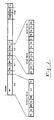
- a time frame is shown in which a common data rate for all receivers or participants T1, T2 ... T n is used to mark the beginning of a frame to identify.
- you divide the transmission frame into 33 time intervals ZI, for example, which are assigned to a reference burst ZI0 and 32 subscribers ZI1-ZI32 you can send a control burst SB1 .... SB32 in every time interval, i.e. a packet or pulse train ( Burst) with a fixed rate that is understandable for each participant and use the remaining part of the time interval for a data burst DB with a variable data rate D. Only the time interval ZI2 is drawn here; ZI1 ... ZI32 are also constructed.
- control burst SB With the fixed rate, in order to enable the receiver to switch to the selected variable frequency in good time (via frequency information).
- this control burst SB can also carry the target address ZA for the following burst and thus inform the receiver circuit that a time interval is now available. This is particularly important so that a recipient who can show or hide the information that is intended for him or for other participants with a time mask. It is conceivable that the different data rates in the time intervals could otherwise lead to interference.
- the receiver examines the data stream, looks at the control bursts SB of all participants and evaluates them, and then uses the address to decide whether a control burst has been sent to them. All control bursts of a frame, which it has registered as being sent for itself, are switched through together with the associated data bursts in the receiver; all others are blocked early in the preamplifiers of the receiver, so that interference cannot occur. To control this time mask, the length of the burst is also made variable Transfer data rate so that you can control the mask very precisely in time.
- the frame structure of a preferred embodiment of the invention is described in detail below.
- the frame ( Figure 2) consists of 33 time intervals that are transmitted in turn.
- the reference burst RB is located in the time interval 0. This has the task of marking the beginning of a frame and also serves to measure the distance between the control center and the subscriber.
- Control and data bursts are sent in the remaining 32 time intervals ZI1 ... ZI32. There are protection times S between the individual time intervals. Control and data bursts are also separated from one another by protection times within the time intervals.
- the reference and control bursts have a fixed data rate that can be understood by all receivers in the central office and at the subscriber.
- the control burst consists of PR: preamble, SW: start word, TY: type, BE: assignment, ZA: destination address, D: data rate, DA: data and PS: checksum.
- the preamble provides the receiver in the central office or at the subscriber with the necessary clock information in order to establish bit synchronism for the control burst.
- the start word marks the beginning of the relevant information.
- the type field TY contains information as to whether the user data are transmitted in a separate data burst DB or in the data field DA of the control burst in the corresponding time interval. When transmitting in the control burst SB, this fills the entire time interval.
- the occupancy field BE indicates whether user data are transmitted in the data field or not.
- the destination address ZA is used to address a subscriber.
- the data rate field D passes the information to the recipient at the central office or at the subscriber which data rate the data burst DB is transmitted in the same time interval.
- the receiver can be programmed to the respective data rate or that it can process a large range of data rates. Since there are optical receivers that can process data rates between 1 Mbit / s and 50 Mbit / s, for example, by programming the clock recovery circuit to one of approx. 50 available frequency bands, it is sufficient in this case if you have an identifier for the sends the relevant frequency band to be transmitted data rate.
- the checksum PS is formed on the transmission side via all bits between the start of the type field and the end of the data field and is also transmitted. This means that the recipient can track down transmission errors.
- the data burst consists of PR: preamble, SW: start word, DA: data and PS: checksum. Since the occupancy, destination address and data rate of the data burst are already transmitted in the control burst, this information can be omitted in the data burst.
- the data burst has its own preamble PR, which is also used for bit synchronization. This is followed by the start word SW, which marks the start of the user data.
- the user data are packed into the data field DA and the checksum calculated using this user data is transmitted in the following checksum field PS.
- the reference burst consists of PR: preamble, SW: start word, RKW: frame identification word, ZA: destination address, EMW, distance measurement word, ELZ: echo runtime and PS: checksum.
- the reference burst also begins with the preamble and start word.
- the frame identifier marks the beginning of a new frame.
- the subsequent destination address ZA addresses the subscriber who is to carry out a distance measurement in the current frame by sending the received reference burst back to the central connection unit ZAE immediately after recognizing the frame identification word, its own address and the distance measurement word EMW.
- the echo delay time ELZ is the time reserved within the frame that the subscriber needs to send the echo back over the fiber optic cable.
- the checksum PS is formed over all bits of the target address, the distance measurement word and the echo delay.
- the data burst with the variable data rate can therefore also be eliminated in one time interval (or in several time intervals), so that only the control burst still exists.
- the control burst SB also contains the data part with the user data.
- the information about the address, length and frequency before the data part relates to the burst itself.
- the frequency specification is of no interest, since all receivers can process the fixed frequency or data rate.
- the advantage of this measure is that there can also be very inexpensive receivers that can only receive at this fixed data rate and still work in the mixed system.
- a reference burst RB is first sent, which makes the run times measurable for the individual participants.
- the reference burst has an internal identifier.
- the control center can measure the duration of the burst up to the subscriber and back, how long the transit time to to the participant. From this it can be deduced how much delay the subscriber has to send in the reverse direction in order to send without collision. This allows the gap to be reduced to a few bit positions, for example, so that a better yield in the data rate is obtained.
- a preferred exemplary embodiment of the invention for the subscriber group interface unit TGAE is described below with reference to the block diagram of FIG. 3.
- the time-division multiplex signals are obtained via an optical fiber line in the optical receiver OE.
- the subscriber group interface unit TGAE in FIG. 3 receives from the central interface unit ZAE, which will be described below, a time-division multiplex frame which carries different data rates D in the individual time intervals (see FIG. 2).
- the optical receiver OE works in broadband and can do it all - or those for the services required at the subscriber - process data rates.
- the signal detector SD reports to the masking control MS when a valid burst is present at the output of the optical receiver.
- the masking control MS can uniquely recognize the reference burst RB by its length and can generate a time mask therefrom which initially switches the optical receiver OE transparent only for the reference and control bursts.
- the clock recovery TG is first programmed to the fixed data rate of the reference and control bursts. These bursts are regenerated in time in the data regenerator DR and decoded in the channel decoder KD.
- the demultiplexer DM routes the reference and control bursts to the respective burst receivers. These separate the useful information from the preamble and start word, calculate the checksums and compare them with the transmitted checksums.
- the reference burst receiver RE also evaluates the frame code word RKW and compares the received destination address with its own TGAE address. If the addresses match, the distance measurement word EMW is forwarded to the EMW detector. If it receives a correct EMW, it gives the reference burst generator the command to generate a reference burst. At the same time, a loop is switched that sends the reference burst generated in this way back to the ZAE.
- the control burst receiver SE evaluates the destination address ZA in the control burst. If this corresponds to the own TGAE address, the information in the type field decides whether a data burst with user data follows or the user data is in the data field of the control burst. If an occupied data burst follows the control burst, the data rate is communicated to the data burst receiver DE and the data rate controller DS. At the end of the control burst, the clock recovery circuit TG and the data burst receiver DE is automatically reprogrammed to the new data rate. The reprogramming must take place during the protection time S between the control and data burst. At the end of the data burst, the old data rate is reprogrammed, etc.
- the control burst receiver SE also makes the optical receiver OE transparent to the duration of the data burst via the masking control MS when it is addressed to its own TGAE.
- Runtime compensation is an electronic memory with programmable depth and lead time.
- the decompression memories D1 and D2 receive the time-compressed data packets from the data or control burst receivers and convert them into continuous-time data streams.
- the adaptation unit AE (“Line Interface Unit") adapts the user and control data to the subscriber terminal.
- the subscriber terminal passes on continuous time useful and control data via the adaptation unit AE to the compression memories K1 and K2.
- the compression memories collect the continuous useful and control data intended for a packet and send them to the corresponding burst generators in a time-compressed manner. These pack the user data together with the preamble, the start word and the checksum into the intended package structure.
- the burst generators generate the control, data and reference bursts, which are combined in the multiplexer MX to form a data stream.
- the runtime compensation LA shifts the transmission time of this data stream so that the data streams of all TGAEs in the star point in front of the ZAE change to a collision-free time Assemble time-division multiplex frames.
- clock information is added to the data stream via the line coding.
- the optical transmitter OS converts the electrical line-coded data signal into an optical data signal, which is sent to the ZAE.
- the optical fibers in the associated cable distributor KVZ are interconnected with the help of star couplers to one bus each for the direction of the switching subscriber and vice versa.
- the two star couplers are connected with a pair of fibers to a central interface unit ZAE in the exchange.
- a repeater with amplitude regeneration is also provided in the KVZ.
- the principle of the system is that data blocks are transmitted regularly between the ZAE and the subscriber group interface units TGAE, which enable permanent communication between all end users and the exchange.
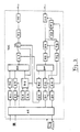
- the central interface unit ZAE (see Fig. 4) has a very similar structure.
- the optical receiver OE is a broadband receiver that can process different data rates D.
- the data rate comes from the optical receiver to the data regenerator DR. This has the task of regenerating the data in time together with the clock recovery circuit TG.
- the clock recovery is a programmable unit which is programmed to a data rate D via the "data rate" control and can then perform a regeneration for this data rate together with the data regenerator DR.
- the signal detector SD decides when incoming data is available and communicates this to the masking control MS. This can then only be the bursts with fixed Let the data rate through so that the receiver can first check what is being sent in the data bursts that follow the control bursts, or at what data rate is being sent there.
- the process is as follows: first, for example, there is a control burst with a fixed data rate, the clock recovery is then programmed to this fixed data rate. The data rate at which the subsequent data burst is sent is transferred in this control burst, and as soon as the control burst has ended, the clock recovery is immediately reprogrammed to this new data rate indication, so that subsequently the data rate contained in the data burst is received can be. It is important here that in the ZAE the clock recovery circuit is continuously reprogrammed in a data frame, so that when a reference burst or a control burst is received which are sent at a fixed data rate, the clock recovery is programmed to this fixed data rate. When changing to a data burst, the existing data rate is reprogrammed. For the clock recovery circuit, this means that it can be completely reprogrammed within the protection times. The protection time should be chosen accordingly.
- the main difference between the TGAE and the ZAE is that the ZAE generates a reference burst with the associated address and sends it to the TGAE.
- the addressed TGAE then closes a loop switch SL and sends the echo of this reference burst back to the ZAE.
- the ZAE receives this echo in its optical reception branch and measures the transit time between the transmission of the reference burst and the returning echo.
- the control computer SR evaluates the measured runtime and outputs certain bits of the distance measurement word forward the information to the TGAE, which it needs to adjust the runtime compensation according to the measurement value.
- This means that all TGAEs connected to a ZAE can set their round trip time, ie the running time between ZAE, TGAE and back to the ZAE to a uniform value. This means that the message transmission between the ZAE and any TGAE is always standardized to a fixed runtime.
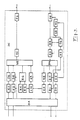
- the ZAE in FIG. 5 there are separate receiver circuits after the optical receiver and preamplifier OE 2.
- the upper branch understands the fixed data rate that is always present in the reference burst and in the control burst.
- the lower branch processes the changing data rate of the data burst, which can have a different data rate coming from a subscriber.
- the reprogramming of the clock recovery circuit in the lower data branch is now to be carried out in longer periods, as soon as e.g. Data burst 1 has been completely transmitted, the reprogramming for the reception of the data burst 2 can take place in the period of the control burst and in the subsequent protection time. This time is longer than the time between the control burst and the subsequent data burst, which is present in the ZAE as the reprogramming time.
- a time masking MS is necessary, which is carried out by a signal detector SD is controlled.
- the signal detector SD reports when data is available and when there is no data. Since the reference burst represents the longest data transmission in a block in time, the position of the reference burst in time can in principle also be determined directly with the signal detector SD.
- a mask is then controlled in such a way that only the reference burst and, for example, all control bursts are initially passed through. This is only important for the electronics participants.
- the addresses are checked in the control burst and then a decision is made: this is your own address, ie the information relevant to the subscriber is available.
- this is your own address, ie the information relevant to the subscriber is available.
- the bursts with the mask that must be processed for the respective subscriber are then released.
Abstract
Description
Die Erfindung betrifft ein Verfahren zum Übertragen von Daten unterschiedlicher Rate nach dem Oberbegriff des Anspruchs 1. Die Zeitmultiplextechnik ist bekannt. In der Regel handelt es sich um synchrone Übertragungsverfahren, d.h. Daten werden mit einer konstanten Bitrate übertragen, wobei es einen Rahmen gibt, der in verschiedene Zeitintervalle unterteilt ist. In jedes Zeitintervall wird Information - beispielsweise für einen Teilnehmer - gepackt, so daß man eine Mehrfachausnutzung der Übertragungsleitung erreicht. Um die Zuordnung der einzelnen Zeitintervalle zu einzelnen Teilnehmern zu gewährleisten, schickt man beispielsweise am Anfang eines Rahmens Kennungswörter, die dessen Anfang kennzeichnen.The invention relates to a method for transmitting data at different rates according to the preamble of
Die Aufgabe der Erfindung besteht darin, einen Zeitmultiplexrahmen zu entwickeln, der es ermöglicht, Daten mit unterschiedlichen Raten in einem Zeitrahmen zu synchronisieren. Diese Aufgabe wird gemäß der Erfindung durch die im Kennzeichen des Anspruchs 1 erwähnten Merkmale gelöst. Weiterbildungen der Erfindung sind in den Unteransprüchen enthalten.The object of the invention is to develop a time-division multiplex frame which makes it possible to synchronize data at different rates in one time frame. This object is achieved according to the invention by the features mentioned in the characterizing part of
Ausführungsbeispiele der Erfindung werden nachstehend anhand der Zeichnung näher erläutert; dabei zeigt:
Figur 1- ein Übertragungssystem,
Figur 2- einen Zeitrahmen,
- Figur 3
- ein Blockschaltbild einer Teilnehmergruppen-Anschalteinheit,
- Figur 4
- ein Blockschaltbild einer zentralen Anschalteinheit,
- Figur 5
- ein weiteres Blockschaltbild einer zentralen Anschalteinheit.
- Figure 1
- a transmission system,
- Figure 2
- a time frame
- Figure 3
- a block diagram of a subscriber group interface unit,
- Figure 4
- a block diagram of a central interface unit,
- Figure 5
- another block diagram of a central interface unit.
Die Erfindung wird beispielsweise in lokalen Netzen mit optischer Übertragung angewendet. Will man in den einzelnen Zeitintervallen eines Zeitrahmens variable Datenraten zulassen, so ist den einzelnen Teilnehmern T₁ , T₂ ... Tn zunächst mitzuteilen, wo der Beginn des Rahmens liegt. Dies bezieht sich auf den Empfang eines Datenstroms, der über eine gemeinsame Leitung, d.h. das Hauptkabel HK (s. Figur 1), den Kabelverzweiger KVZ und die teilnehmerseitige Multiplex-Einrichtung oder Teilnehmergruppen-Anschalteinheit TGAE zu den einzelnen Teilnehmern gelangt. In der Gegenrichtung ordnet die TGAE dem sendenden Teilnehmer eines der freien Zeitintervalle zu und sendet die Information an die zentrale Multiplex-Einrichtung ZAE. Diese ist Teil eines privaten oder öffentlichen Netzes.The invention is used for example in local area networks with optical transmission. If you want to allow variable data rates in the individual time intervals of a time frame, the
Die Schwierigkeit besteht darin, daß von den Teilnehmern unterschiedliche Frequenzen, d.h. Datenraten angeboten oder benutzt werden und man im Prinzip eine gemeinsame Datenrate benötigt, um allen Teilnehmern T₁ , T₂ ... Tn mitzuteilen, wo der Beginn des Rahmens liegt. Eine zweite Lösung wäre eine Rahmenkennung zu senden, die auf einem analogen Verfahren beruht, bei dem der Empfänger nicht gezwungen ist, eine gemeinsame Datenrate zu verstehen.The difficulty is that different frequencies, ie data rates are offered or used by the participants and you in principle need a common data rate to tell all participants T₁, T₂ ... T n where the beginning of the frame is. A second solution would be to send a frame identifier which is based on an analog method in which the receiver is not forced to understand a common data rate.
Wie in Fig. 1 dargestellt, gelangen alle Daten vom Hauptverteiler HVT zu einer zentralen Anschalteinheit ZAE, die gesondert dargestellt und besprochen wird.As shown in Fig. 1, all data from the main distributor HVT to a central interface unit ZAE, which is shown and discussed separately.
In Figur 2 wird ein Zeitrahmen dargestellt, in dem eine gemeinsame Datenrate für alle Empfänger oder Teilnehmer T₁ , T₂ ... Tn benutzt wird, um diesen den Anfang eines Rahmens kenntlich zu machen. Teilt man den Übertragungsrahmen beispielsweise in 33 Zeitintervalle ZI auf, die einem Referenz-Burst ZI0 und 32 Teilnehmern ZI1-ZI32 zugeordnet sind, so kann man in jedem Zeitintervall einen Steuer-Burst SB1 ....SB32 senden, d.h. ein Paket oder Impulsfolge (Burst) mit einer festen Rate, das für jeden Teilnehmer verständlich ist und den restlichen Teil des Zeitintervalls für einen Daten-Burst DB mit einer variablen Datenrate D benutzen. Hier ist nur das Zeitintervall ZI2 gezeichnet; ZI1 ... ZI32 sind ebenso aufgebaut. In den Steuer-Burst SB mit der festen Rate wird dann die Information gelegt, die den darauf folgenden Daten-Burst mit variabler Datenrate D kennzeichnet, um es dem Empfänger zu ermöglichen, rechtzeitig auf die ausgewählte variable Frequenz umzuschalten (über eine Frequenzinformation). Neben dieser Frequenzinformation kann dieser Steuer-Burst SB zusätzlich die Ziel-Adresse ZA für den darauf folgenden Burst tragen und somit der Empfängerschaltung mitteilen, daß jetzt ein Zeitintervall zu seiner Verfügung steht. Dies ist insbesondere deshalb wichtig, damit ein Empfänger, der die Informationen, die für ihn bestimmt sind oder für andere Teilnehmer, mit einer zeitlichen Maske ein- bzw. ausblenden kann. Es ist vorstellbar, daß es sonst durch die unterschiedlichen Datenraten in den Zeitintervallen zu Störungen kommen kann.In Figure 2, a time frame is shown in which a common data rate for all receivers or participants T₁, T₂ ... T n is used to mark the beginning of a frame to identify. If you divide the transmission frame into 33 time intervals ZI, for example, which are assigned to a reference burst ZI0 and 32 subscribers ZI1-ZI32, you can send a control burst SB1 .... SB32 in every time interval, i.e. a packet or pulse train ( Burst) with a fixed rate that is understandable for each participant and use the remaining part of the time interval for a data burst DB with a variable data rate D. Only the time interval ZI2 is drawn here; ZI1 ... ZI32 are also constructed. The information that identifies the subsequent data burst with variable data rate D is then placed in the control burst SB with the fixed rate, in order to enable the receiver to switch to the selected variable frequency in good time (via frequency information). In addition to this frequency information, this control burst SB can also carry the target address ZA for the following burst and thus inform the receiver circuit that a time interval is now available. This is particularly important so that a recipient who can show or hide the information that is intended for him or for other participants with a time mask. It is conceivable that the different data rates in the time intervals could otherwise lead to interference.
In der Regel wird es so sein, daß der Empfänger den Datenstrom untersucht, sich die Steuer-Bursts SB aller Teilnehmer ansieht und auswertet und dann nach der Adresse entscheidet, ob ein Steuer-Burst an ihn gesendet worden ist. Alle Steuer-Bursts eines Rahmens, die er als für sich gesendet registriert hat, werden zusammen mit den zugehörigen Daten-Bursts im Empfänger durchgeschaltet, alle anderen werden frühzeitig in den Vorverstärkern des Empfängers blockiert, so daß es nicht zu Störungen kommen kann. Zur Steuerung dieser zeitlichen Maske wird außerdem die Länge des Bursts mit variabler Datenrate übertragen, so daß man die Maske sehr genau zeitlich steuern kann.As a rule, it will be the case that the receiver examines the data stream, looks at the control bursts SB of all participants and evaluates them, and then uses the address to decide whether a control burst has been sent to them. All control bursts of a frame, which it has registered as being sent for itself, are switched through together with the associated data bursts in the receiver; all others are blocked early in the preamplifiers of the receiver, so that interference cannot occur. To control this time mask, the length of the burst is also made variable Transfer data rate so that you can control the mask very precisely in time.
Im folgenden wird der Rahmenaufbau an einer bevorzugten Ausführungsform der Erfindung und im Detail geschildert. Der Rahmen (Figur 2) besteht aus 33 Zeitintervallen, die reihum gesendet werden. Im Zeitintervall 0 befindet sich der Referenz-Burst RB. Dieser hat die Aufgabe den Beginn eines Rahmens zu kennzeichnen und dient außerdem der Entfernungsmessung zwischen Zentrale und Teilnehmer. In den verbleibenden 32 Zeitintervallen ZI1 ... ZI32 werden Steuer- und Daten-Bursts gesendet. Zwischen den einzelnen Zeitintervallen befinden sich Schutzzeiten S. Innerhalb der Zeitintervalle werden Steuer- und Daten-Burst ebenfalls durch Schutzzeiten voneinander getrennt. Die Referenz- und Steuer-Bursts besitzen eine feste Datenrate, die von allen Empfängern in der Zentrale und beim Teilnehmer verstanden werden.The frame structure of a preferred embodiment of the invention is described in detail below. The frame (Figure 2) consists of 33 time intervals that are transmitted in turn. The reference burst RB is located in the time interval 0. This has the task of marking the beginning of a frame and also serves to measure the distance between the control center and the subscriber. Control and data bursts are sent in the remaining 32 time intervals ZI1 ... ZI32. There are protection times S between the individual time intervals. Control and data bursts are also separated from one another by protection times within the time intervals. The reference and control bursts have a fixed data rate that can be understood by all receivers in the central office and at the subscriber.
Im folgenden sollen die unterschiedlichen Bursts näher erläutert werden. Der Steuer-Burst besteht aus PR: Präambel, SW: Startwort, TY: Type, BE: Belegung, ZA: Zieladresse, D: Datenrate, DA: Daten und PS: Prüfsumme. Die Präambel liefert dem Empfänger in der Zentrale bzw. beim Teilnehmer die notwendige Taktinformation, um die Bitsynchronität für den Steuer-Burst herzustellen. Das Startwort kennzeichnet den Beginn der relevanten Information. Im Type-Feld TY steht die Information, ob im entsprechenden Zeitintervall die Nutzdaten in einem getrennten Daten-Burst DB oder im Daten-Feld DA des Steuer-Bursts übertragen werden. Bei der Übertragung im Steuer-Burst SB, füllt dieser das gesamte Zeitintervall aus. Das Belegungs-Feld BE zeigt an, ob Nutzdaten im Datenfeld übertragen werden oder nicht. Die Zieladresse ZA dient der Adressierung eines Teilnehmers. Das Datenraten-Feld D übergibt dem Empfänger in der Zentrale bzw. beim Teilnehmer die Information, mit welcher Datenrate der Daten-Burst DB im gleichen Zeitintervall übertragen wird.The different bursts are explained in more detail below. The control burst consists of PR: preamble, SW: start word, TY: type, BE: assignment, ZA: destination address, D: data rate, DA: data and PS: checksum. The preamble provides the receiver in the central office or at the subscriber with the necessary clock information in order to establish bit synchronism for the control burst. The start word marks the beginning of the relevant information. The type field TY contains information as to whether the user data are transmitted in a separate data burst DB or in the data field DA of the control burst in the corresponding time interval. When transmitting in the control burst SB, this fills the entire time interval. The occupancy field BE indicates whether user data are transmitted in the data field or not. The destination address ZA is used to address a subscriber. The data rate field D passes the information to the recipient at the central office or at the subscriber which data rate the data burst DB is transmitted in the same time interval.
Hierbei kann es sich um eine für den Empfänger unbekannte Datenrate handeln, die ihm exakt mit entsprechender Fehlersicherung mitgeteilt wird, um sich auf den darauffolgenden Daten-Burst synchronisieren zu können. Voraussetzung ist allerdings, daß der Empfänger auf die jeweilige Datenrate programmierbar ist, bzw. daß er einen großen Bereich von Datenraten verarbeiten kann. Da es optische Empfänger gibt, die beispielsweise Datenraten zwischen 1 MBit/s und 50 MBit/s verarbeiten können, indem man beispielsweise die Taktrückgewinnungsschaltung auf ein von ca. 50 vorhandenen Frequenzbändern programmiert, reicht es in diesem Fall, wenn man eine Kennung zu dem für die zu übertragende Datenrate relevanten Frequenzband sendet. Die Prüfsumme PS wird sendeseitig über alle Bits zwischen Beginn des Type-Feldes und Ende des Daten-Feldes gebildet und mitübertragen. Beim Empfänger besteht somit die Möglichkeit, Übertragungsfehler aufzuspüren.This can be a data rate unknown to the recipient, which is communicated to him precisely with appropriate error protection in order to be able to synchronize with the subsequent data burst. However, it is a prerequisite that the receiver can be programmed to the respective data rate or that it can process a large range of data rates. Since there are optical receivers that can process data rates between 1 Mbit / s and 50 Mbit / s, for example, by programming the clock recovery circuit to one of approx. 50 available frequency bands, it is sufficient in this case if you have an identifier for the sends the relevant frequency band to be transmitted data rate. The checksum PS is formed on the transmission side via all bits between the start of the type field and the end of the data field and is also transmitted. This means that the recipient can track down transmission errors.
Der Daten-Burst besteht aus PR: Präambel, SW: Startwort, DA: Daten und PS: Prüfsumme. Da bereits im Steuer-Burst die Belegung, Zieladresse und Datenrate des Daten-Bursts übermittelt wird, können diese Angaben im Daten-Burst entfallen. Der Daten-Burst besitzt eine eigene Präambel PR, die auch hier der Bitsynchronisation dient. Darauf folgt das Startwort SW, welches den Beginn der Nutzdaten kennzeichnet. Die Nutzdaten werden ins Daten-Feld DA gepackt und die über diese Nutzdaten berechnete Prüfsumme in dem darauffolgenden Prüfsummen-Feld PS übertragen.The data burst consists of PR: preamble, SW: start word, DA: data and PS: checksum. Since the occupancy, destination address and data rate of the data burst are already transmitted in the control burst, this information can be omitted in the data burst. The data burst has its own preamble PR, which is also used for bit synchronization. This is followed by the start word SW, which marks the start of the user data. The user data are packed into the data field DA and the checksum calculated using this user data is transmitted in the following checksum field PS.
Der Referenz-Burst besteht aus PR: Präambel, SW: Startwort, RKW: Rahmenkennungswort, ZA: Zieladresse, EMW, Entfernungsmeßwort, ELZ: Echolaufzeit und PS: Prüfsumme. Der Referenz-Burst beginnt ebenfalls mit Präambel und Startwort. Das Rahmenkennungswort kennzeichnet den Beginn eines neuen Rahmens. Die darauffolgende Zieladresse ZA adressiert den Teilnehmer, der im laufenden Rahmen eine Entfernungsmessung durchführen soll, indem er den empfangenen Referenz-Burst unmittelbar nach Erkennen des Rahmenkennungswortes, seiner eigenen Adresse und des Entfernungs-Meßwortes EMW zurück zur Zentralen Anschalteinheit ZAE sendet. Die Echolaufzeit ELZ ist die im Rahmen reservierte Zeit, die der Teilnehmer zum Zurücksenden des Echos über das LWL-Kabel benötigt. Die Prüfsumme PS wird über alle Bits der Zieladresse, des Entfernungsmeßwortes und der Echolaufzeit gebildet.The reference burst consists of PR: preamble, SW: start word, RKW: frame identification word, ZA: destination address, EMW, distance measurement word, ELZ: echo runtime and PS: checksum. The reference burst also begins with the preamble and start word. The frame identifier marks the beginning of a new frame. The subsequent destination address ZA addresses the subscriber who is to carry out a distance measurement in the current frame by sending the received reference burst back to the central connection unit ZAE immediately after recognizing the frame identification word, its own address and the distance measurement word EMW. The echo delay time ELZ is the time reserved within the frame that the subscriber needs to send the echo back over the fiber optic cable. The checksum PS is formed over all bits of the target address, the distance measurement word and the echo delay.
Der Daten-Burst mit der variablen Datenrate kann also in einem Zeitintervall auch wegfallen (oder auch in mehreren Zeitintervallen), so daß nur noch der Steuer-Burst existiert. Dann enthält der Steuer-Burst SB auch den Datenteil mit den Nutzdaten. Die vor dem Datenteil stehenden Informationen über Adresse, Länge und Frequenz beziehen sich in dem Fall auf den Burst selbst. Die Frequenzangabe ist in diesem Fall uninteressant, da alle Empfänger die feste Frequenz oder Datenrate verarbeiten können. Der Vorteil dieser Maßnahme besteht darin, daß es auch sehr preiswerte Empfänger geben kann, die nur mit dieser festen Datenrate empfangen und dennoch in dem gemischten System arbeiten können.The data burst with the variable data rate can therefore also be eliminated in one time interval (or in several time intervals), so that only the control burst still exists. Then the control burst SB also contains the data part with the user data. In this case, the information about the address, length and frequency before the data part relates to the burst itself. In this case, the frequency specification is of no interest, since all receivers can process the fixed frequency or data rate. The advantage of this measure is that there can also be very inexpensive receivers that can only receive at this fixed data rate and still work in the mixed system.
Alternativ zu der in Figur 2 angegebenen Rahmenstruktur ist es auch vorstellbar, daß man in einem Rahmen alle Steuer-Bursts zu einem Burst zusammenfaßt und in diesem zentralen Steuer-Burst alle relevanten Informationen über alle Zeitintervalle im Rahmen zusammenfaßt und z.B. eine Tabelle verwaltet, in der die Zuordnung der einzelnen Zeitintervalle zu den Teilnehmern festgelegt wird und außerdem die Frequenzinformation für jedes Zeitintervall enthalten ist. Wählt man eine feste Rahmenlänge und teilt diese Rahmenlänge in eine feste Anzahl n+1 von Zeitintervallen - in unserem Beispiel ist die Zahl der Teilnehmer 32 - auf, so spielt die Übermittlung der Burst-Länge keine Rolle.As an alternative to the frame structure shown in Figure 2, it is also conceivable that all control bursts are combined in one frame in a frame and all relevant information about all time intervals are combined in the frame in this central control burst and, for example, a table is administered in which the assignment of the individual time intervals to the participants is determined and the frequency information for each time interval is also included. Chooses If you have a fixed frame length and divide this frame length into a fixed number n + 1 of time intervals - in our example the number of participants is 32 - the transmission of the burst length is irrelevant.
Zwischen den einzelnen Bursts befinden sich Schutzzeiten S. Diese Schutzzeiten S müssen beim Betrieb auf einem Bus optischer oder elektrischer Art immer so groß gewählt werden, daß es keine Kollision von Daten gibt. Um diese Lücken dennoch kürzer zu gestalten und eine bessere Ausnutzung der Datenleitungen zu gewährleisten, wird zunächst ein Referenz-Burst RB geschickt, der die Laufzeiten zu den einzelnen Teilnehmern meßbar macht. Der Referenz-Burst besitzt eine interne Kennung. Sobald der Teilnehmer den Referenz-Burst erkennt und seine Adresse darin findet, soll er diesen Referenz-Burst - quasi als Echo - direkt zurücksenden, so daß die Zentrale über die Laufzeit des Burst bis zum Teilnehmer und zurück messen kann, wie groß die Laufzeit bis zum Teilnehmer ist. Daraus kann abgeleitet werden, mit wieviel Verzögerung der Teilnehmer in der Rückrichtung senden muß, um kollisionsfrei zu senden. Dadurch kann man die Lücke beispielsweise auf einige Bitstellen reduzieren, so daß man eine bessere Ausbeute in der Datenrate erhält.There are protection times S between the individual bursts. When operating on a bus of optical or electrical type, these protection times S must always be chosen so large that there is no collision of data. In order to make these gaps shorter and to ensure better utilization of the data lines, a reference burst RB is first sent, which makes the run times measurable for the individual participants. The reference burst has an internal identifier. As soon as the subscriber recognizes the reference burst and finds his address in it, he should send this reference burst - quasi as an echo - directly, so that the control center can measure the duration of the burst up to the subscriber and back, how long the transit time to to the participant. From this it can be deduced how much delay the subscriber has to send in the reverse direction in order to send without collision. This allows the gap to be reduced to a few bit positions, for example, so that a better yield in the data rate is obtained.
Im folgenden wird ein bevorzugtes Ausführungsbeispiel der Erfindung für die Teilnehmergruppen-Anschalteinheit TGAE anhand des Blockschaltbildes der Fig. 3 beschrieben. Man bekommt die Zeitmultiplexsignale über eine LWL-Leitung in den optischen Empfänger OE. Die Teilnehmergruppen-Anschalteinheit TGAE in Fig. 3 erhält von der Zentralen Anschalteeinheit ZAE, welche anschließend beschrieben wird, einen Zeitmultiplexrahmen, der in den einzelnen Zeitintervallen unterschiedliche Datenraten D trägt (s. Fig. 2). Der optische Empfänger OE arbeitet breitbandig und kann alle - bzw. die für die Dienste beim Teilnehmer benötigten - Datenraten verarbeiten. Der Signaldetektor SD meldet der Maskierungssteuerung MS, wann ein gültiger Burst am Ausgang des optischen Empfängers anliegt. Die Maskierungssteuerung MS kann den Referenz-Burst RB eindeutig an seiner Länge erkennen und daraus ein Zeitmaske generieren, die den optischen Empfänger OE zunächst nur für die Referenz- und Steuer-Bursts transparent schaltet. Die Taktrückgewinnung TG ist zunächst auf die feste Datenrate der Referenz- und Steuer-Bursts programmiert. Diese Bursts werden im Daten-Regenerator DR zeitlich regeneriert und im Kanal-Decoder KD decodiert. Der Demultiplexer DM leitet die Referenz- und Steuer-Bursts zu den jeweiligen Burst-Empfängern. Diese trennen die Nutzinformation von Präambel und Startwort, berechnen die Prüfsummen und vergleichen diese mit der übertragenen Prüfsummen.A preferred exemplary embodiment of the invention for the subscriber group interface unit TGAE is described below with reference to the block diagram of FIG. 3. The time-division multiplex signals are obtained via an optical fiber line in the optical receiver OE. The subscriber group interface unit TGAE in FIG. 3 receives from the central interface unit ZAE, which will be described below, a time-division multiplex frame which carries different data rates D in the individual time intervals (see FIG. 2). The optical receiver OE works in broadband and can do it all - or those for the services required at the subscriber - process data rates. The signal detector SD reports to the masking control MS when a valid burst is present at the output of the optical receiver. The masking control MS can uniquely recognize the reference burst RB by its length and can generate a time mask therefrom which initially switches the optical receiver OE transparent only for the reference and control bursts. The clock recovery TG is first programmed to the fixed data rate of the reference and control bursts. These bursts are regenerated in time in the data regenerator DR and decoded in the channel decoder KD. The demultiplexer DM routes the reference and control bursts to the respective burst receivers. These separate the useful information from the preamble and start word, calculate the checksums and compare them with the transmitted checksums.
Der Referenzburst-Empfänger RE wertet zusätzlich das Rahmenkennungswort RKW aus und vergleicht die empfangene Zieladresse mit der eigenen TGAE-Adresse. Stimmen die Adressen überein, so wird das Entfernungsmeßwort EMW an den EMW-Detektor weitergeleitet. Empfängt dieser ein richtiges EMW, so gibt er dem Referenzburst-Generator den Befehl, einen Referenz-Burst zu erzeugen. Gleichzeitig wird eine Schleife geschaltet, die den so erzeugten Referenz-Burst zurück zur ZAE sendet.The reference burst receiver RE also evaluates the frame code word RKW and compares the received destination address with its own TGAE address. If the addresses match, the distance measurement word EMW is forwarded to the EMW detector. If it receives a correct EMW, it gives the reference burst generator the command to generate a reference burst. At the same time, a loop is switched that sends the reference burst generated in this way back to the ZAE.
Der Steuerburst-Empfänger SE wertet die Zieladresse ZA im Steuer-Burst aus. Entspricht diese der eignen TGAE-Adresse, so entscheidet die Information im Typfeld, ob ein Daten-Burst mit Nutzdaten folgt, oder die Nutzdaten im Datenfeld des Steuer-Bursts stehen. Wenn auf den Steuer-Burst ein belegter Daten-Burst folgt, so wird die Datenrate dem Datenburst-Empfänger DE und der Datenraten-Steuerung DS mitgeteilt. Am Ende des Steuer-Bursts werden die Taktrückgewinnungsschaltung TG und der Datenburst-Empfänger DE automatisch auf die neue Datenrate umprogrammiert. Die Umprogrammierung muß während der Schutzzeit S zwischen Steuer- und Daten-Burst erfolgen. Am Ende des Daten-Bursts wird wieder auf die alte Datenrate zurückprogrammiert usw.. Der Steuerburst-Empfänger SE macht außerdem über die Maskierungssteuerung MS den optischen Empfänger OE für die Zeitdauer des Daten-Bursts transparent, wenn er an die eigene TGAE adressiert ist.The control burst receiver SE evaluates the destination address ZA in the control burst. If this corresponds to the own TGAE address, the information in the type field decides whether a data burst with user data follows or the user data is in the data field of the control burst. If an occupied data burst follows the control burst, the data rate is communicated to the data burst receiver DE and the data rate controller DS. At the end of the control burst, the clock recovery circuit TG and the data burst receiver DE is automatically reprogrammed to the new data rate. The reprogramming must take place during the protection time S between the control and data burst. At the end of the data burst, the old data rate is reprogrammed, etc. The control burst receiver SE also makes the optical receiver OE transparent to the duration of the data burst via the masking control MS when it is addressed to its own TGAE.
Im Echolaufzeit-Feld des Referenz-Bursts werden außerdem Service-Bits übertragen, die nach erfolgter Laufzeitmessung den sendeseitigen Laufzeitausgleich LA neu programmieren. Beim Laufzeitausgleich handelt es sich um einen elektronischen Speicher mit programmierbarer Tiefe und Durchlaufzeit.In the echo delay field of the reference burst, service bits are also transmitted which, after the delay measurement has been carried out, reprogram the transmission delay compensation LA on the transmission side. Runtime compensation is an electronic memory with programmable depth and lead time.
Die Dekompressionsspeicher D1 und D2 erhalten die zeitlich komprimierten Datenpakete aus den Daten- bzw. Steuerburst-Empfängern und setzen diese in zeitkontinuierliche Datenströme um. Die Anpassungseinheit AE ("Line Interface Unit") paßt die Nutz- und Steuerdaten an das Teilnehmerendgerät an.The decompression memories D1 and D2 receive the time-compressed data packets from the data or control burst receivers and convert them into continuous-time data streams. The adaptation unit AE ("Line Interface Unit") adapts the user and control data to the subscriber terminal.
Das Teilnehmerendgerät gibt zeitkontinuierliche Nutz- und Steuerdaten über die Anpassungseinheit AE an die Kompressionsspeicher K1 und K2 weiter. Die Kompressionsspeicher sammeln die kontinuierlichen Nutz- und Steuerungsdaten, die für ein Paket bestimmt sind, und senden diese zeitlich komprimiert zu den entsprechenden Burst-Generatoren. Diese packen die Nutzdaten mit der Präambel, dem Startwort und der Prüfsumme zusammen in die vorgesehene Paketstruktur. Die Burst-Generatoren erzeugen die Steuer-, Daten- und Referenz-Bursts, die im Multiplexer MX zu einem Datenstrom zusammengefügt werden. Der Laufzeitausgleich LA verschiebt den Sendezeitpunkt dieses Datenstroms so, daß sich die Datenströme aller TGAEs im Sternpunkt vor der ZAE zeitrichtig zu einem kollisionsfreien Zeitmultiplexrahmen zusammensetzen. Im Kanal-Coder KC werden dem Datenstrom über die Leitungs-Codierung Taktinformationen zugefügt. Der optische Sender OS konvertiert das elektrische leitungs-codierte Datensignal in ein optisches Datensignal, welches zur ZAE gesendet wird.The subscriber terminal passes on continuous time useful and control data via the adaptation unit AE to the compression memories K1 and K2. The compression memories collect the continuous useful and control data intended for a packet and send them to the corresponding burst generators in a time-compressed manner. These pack the user data together with the preamble, the start word and the checksum into the intended package structure. The burst generators generate the control, data and reference bursts, which are combined in the multiplexer MX to form a data stream. The runtime compensation LA shifts the transmission time of this data stream so that the data streams of all TGAEs in the star point in front of the ZAE change to a collision-free time Assemble time-division multiplex frames. In the channel coder KC, clock information is added to the data stream via the line coding. The optical transmitter OS converts the electrical line-coded data signal into an optical data signal, which is sent to the ZAE.
Wie in Fig. 1 dargestellt, werden die optischen Fasern im zugehörigen Kabelverzweiger KVZ mit Hilfe von Sternkopplern zu je einem Bus für die Richtung Vermittlung-Teilnehmer und umgekehrt verschaltet. Die beiden Sternkoppler werden mit einem Faserpaar an eine zentrale Anschalteeinheit ZAE in der Vermittlung angeschlossen. Für größere Entfernungen ist im KVZ zusätzlich ein Repeater mit Amplitudenregeneration vorgesehen.As shown in Fig. 1, the optical fibers in the associated cable distributor KVZ are interconnected with the help of star couplers to one bus each for the direction of the switching subscriber and vice versa. The two star couplers are connected with a pair of fibers to a central interface unit ZAE in the exchange. For longer distances, a repeater with amplitude regeneration is also provided in the KVZ.
Das Prinzip des Systems ist, daß zwischen der ZAE und den Teilnehmergruppen-Anschalteeinheiten TGAE regelmäßig Datenblöcke übertragen werden, die eine dauerhafte Kommunikation zwischen allen Endteilnehmern und der Vermittlung ermöglichen.The principle of the system is that data blocks are transmitted regularly between the ZAE and the subscriber group interface units TGAE, which enable permanent communication between all end users and the exchange.
Die Zentrale Anschalteinheit ZAE (s. Fig. 4) ist ganz ähnlich aufgebaut. Der optische Empfänger OE ist ein breitbandiger Empfänger, der verschiedene Datenraten D bearbeiten kann. Aus dem optischen Empfänger gelangt die Datenrate zum Datenregenerator DR. Dieser hat die Aufgabe, zusammen mit der Taktrückgewinnungsschaltung TG die Daten zeitlich zu regenerieren. Die Taktrückgewinnung ist eine programmierbare Einheit, die über die Steuerung "Datenrate" auf eine Datenrate D programmiert wird und für diese Datenrate dann zusammen mit dem Datenregenerator DR eine Regeneration durchführen kann. Der Signaldetektor SD entscheidet, wann ankommende Daten vorhanden sind und teilt das der Maskierungssteuerung MS mit. Diese kann dann zunächst einmal nur die Bursts mit fester Datenrate durchlassen, damit der Empfänger zunächst einmal nachsehen kann, was in den Daten-Bursts, die auf die Steuer-Bursts folgen, gesendet wird, oder mit welcher Datenrate dort gesendet wird.The central interface unit ZAE (see Fig. 4) has a very similar structure. The optical receiver OE is a broadband receiver that can process different data rates D. The data rate comes from the optical receiver to the data regenerator DR. This has the task of regenerating the data in time together with the clock recovery circuit TG. The clock recovery is a programmable unit which is programmed to a data rate D via the "data rate" control and can then perform a regeneration for this data rate together with the data regenerator DR. The signal detector SD decides when incoming data is available and communicates this to the masking control MS. This can then only be the bursts with fixed Let the data rate through so that the receiver can first check what is being sent in the data bursts that follow the control bursts, or at what data rate is being sent there.
Der Ablauf ist also wie bei der TGAE folgender: zuerst kommt beispielsweise ein Steuer-Burst mit fester Datenrate, die Taktrückgewinnung wird dann auf diese feste Datenrate programmiert. In diesem Steuer-Burst wird die Datenrate übergeben mit der der darauffolgende Daten-Burst gesendet wird und sobald der Steuer-Burst zu Ende ist, wird unverzüglich die Taktrückgewinnung auf diese neue Datenratenangabe umprogrammiert, so daß darauffolgend mit der im Daten-Burst enthaltenen Datenrate empfangen werden kann. Wichtig hierbei ist, daß bei der ZAE in einem Datenrahmen die Taktrückgewinnungsschaltung fortlaufend umprogrammiert wird, so daß beim Empfang eines Referenz-Bursts oder eines Steuer-Bursts, die mit einer festen Datenrate gesendet werden, die Taktrückgewinnung auf diese feste Datenrate programmiert ist. Beim Wechsel auf einen Daten-Burst wird auf die dann vorhandene Datenrate umprogrammiert. Dies bedeutet für die Taktrückgewinnungsschaltung, daß sie innerhalb der Schutzzeiten vollständig umprogrammierbar ist. Die Schutzzeit ist entsprechend groß zu wählen.As with the TGAE, the process is as follows: first, for example, there is a control burst with a fixed data rate, the clock recovery is then programmed to this fixed data rate. The data rate at which the subsequent data burst is sent is transferred in this control burst, and as soon as the control burst has ended, the clock recovery is immediately reprogrammed to this new data rate indication, so that subsequently the data rate contained in the data burst is received can be. It is important here that in the ZAE the clock recovery circuit is continuously reprogrammed in a data frame, so that when a reference burst or a control burst is received which are sent at a fixed data rate, the clock recovery is programmed to this fixed data rate. When changing to a data burst, the existing data rate is reprogrammed. For the clock recovery circuit, this means that it can be completely reprogrammed within the protection times. The protection time should be chosen accordingly.
Der Unterschied zwischen der TGAE und ZAE besteht im wesentlichen darin, daß die ZAE einen Referenz-Burst mit dazugehöriger Adresse generiert und diesen zur TGAE sendet. Die adressierte TGAE schließt dann einen Schleifenschalter SL und schickt das Echo dieses Referenz-Bursts an die ZAE zurück. Die ZAE empfängt in ihrem optischen Empfangszweig dieses Echo und mißt die Laufzeit zwischen dem Aussenden des Referenz-Bursts und dem zurückkommenden Echo. Der Steuerrechner SR wertet die gemessene Laufzeit aus und gibt mit bestimmten Bits des Entfernungsmeßworts die Information zur TGAE weiter, die diese benötigt, um den Laufzeitausgleich entsprechend des Meßwertes einzustellen. Somit können alle an eine ZAE angeschlossene TGAEs ihre Rundumlaufzeit, d.h. die Laufzeit zwischen ZAE, TGAE und zurück zur ZAE auf einen einheitlichen Wert einstellen. Damit ist die Nachrichtenübertragung zwischen ZAE und beliebiger TGAE immer auf eine feste Laufzeit normiert.The main difference between the TGAE and the ZAE is that the ZAE generates a reference burst with the associated address and sends it to the TGAE. The addressed TGAE then closes a loop switch SL and sends the echo of this reference burst back to the ZAE. The ZAE receives this echo in its optical reception branch and measures the transit time between the transmission of the reference burst and the returning echo. The control computer SR evaluates the measured runtime and outputs certain bits of the distance measurement word forward the information to the TGAE, which it needs to adjust the runtime compensation according to the measurement value. This means that all TGAEs connected to a ZAE can set their round trip time, ie the running time between ZAE, TGAE and back to the ZAE to a uniform value. This means that the message transmission between the ZAE and any TGAE is always standardized to a fixed runtime.
Ein zusätzlicher Unterschied der ZAE besteht darin, daß das Dateninterface OA in der Regel zu einer Vermittlungsstelle geschaltet ist, während die Anpassungseinheit AE oder "Lineinterface" in der TGAE direkt den Anschluß an die Teilnehmer-Endgeräte herstellt.An additional difference of the ZAE is that the data interface OA is usually connected to a switching center, while the adaptation unit AE or "line interface" in the TGAE directly connects to the subscriber terminals.
Bei der ZAE in Figur 5 gibt es nach dem optischen Empfänger und Vorverstärker OE 2 getrennte Empfänger-Schaltkreise. Der obere Zweig versteht die feste Datenrate, die im Referenz-Burst und im Steuer-Burst immer vorliegen. Der untere Zweig verarbeitet die jeweils wechselnde Datenrate des Daten-Burst, der jeweils von einem Teilnehmer kommend unterschiedliche Datenrate haben kann. Die Umprogrammierung der Takt-Rückgewinnungsschaltung im unteren Datenzweig ist jetzt in längeren Zeiträumen vorzunehmen, und zwar sobald z.B. Daten-Burst 1 vollständig übermittelt wurde, kann in dem Zeitraum des Steuer-Burst und in der darauffolgenden Schutzzeit die Umprogrammierung für den Empfang des Daten-Burst 2 erfolgen. Diese Zeit ist länger als die Zeit zwischen Steuer-Burst und darauffolgendem Daten-Burst, die in der ZAE als Umprogrammierzeit vorhanden ist.In the ZAE in FIG. 5 there are separate receiver circuits after the optical receiver and
Damit der Empfänger nicht gestört wird, soll er nur die für ihn relevanten Datenströme verarbeiten. Hierzu wird eine zeitliche Maskierung MS notwendig, die von einem Signal-Detektor SD gesteuert wird. Wenn man die ZAE an den Datenstrom anschaltet, meldet der Signal-Detektor SD, wann Daten vorhanden sind und wann keine Daten vorhanden sind. Da der Referenz-Burst die zeitlich längste Datenübertragung in einem Block darstellt, kann man im Prinzip auch mit dem Signal-Detektor SD direkt die zeitliche Lage des Referenz-Burst ermitteln. Daraufhin wird eine Maske so gesteuert, daß nur der Referenz-Burst und beispielsweise alle Steuer-Bursts zunächst durchgelassen werden. Dies ist nur für die Elektronik-Teilnehmer wichtig. Hier ist zu beachten, daß beispielsweise die Adressen im Steuer-Burst geprüft werden und dann entschieden wird: das ist die eigene Adresse, d.h. die für den Teilnehmer relevante Information vorhanden. Außer diesen Referenz- und Steuer-Bursts werden dann die Bursts mit der Maske freigegeben, die für den jeweiligen Teilnehmer verarbeitet werden müssen.So that the receiver is not disturbed, it should only process the data streams relevant to it. For this purpose, a time masking MS is necessary, which is carried out by a signal detector SD is controlled. When the ZAE is connected to the data stream, the signal detector SD reports when data is available and when there is no data. Since the reference burst represents the longest data transmission in a block in time, the position of the reference burst in time can in principle also be determined directly with the signal detector SD. A mask is then controlled in such a way that only the reference burst and, for example, all control bursts are initially passed through. This is only important for the electronics participants. It should be noted here that, for example, the addresses are checked in the control burst and then a decision is made: this is your own address, ie the information relevant to the subscriber is available. In addition to these reference and control bursts, the bursts with the mask that must be processed for the respective subscriber are then released.
- HVTHVT
- HauptverteilerMain distributor
- KVZKVZ
- KabelverzweigerJunction box
- HKHK
- HauptkabelMain cable
- TGAETGAE
- TeilnehmergruppenanschalteinheitParticipant group interface unit
- ZAEZAE
- Zentrale Multiplex-EinrichtungCentral multiplex facility
- T₁ ... Tn T₁ ... T n
- TeilnehmerAttendees
- BEBE
- Belegung (im Steuer-Burst)Occupancy (in the control burst)
- DATHERE
- Daten allgemeinGeneral data
- DB1DB1
- Datenburst 1Data burst 1
- DBDB
- Datenburst allgemeinGeneral data burst
- DD
- DatenrateData rate
- EMWEMW
- EntfernungsmeßwortDistance measurement word
- ELZELZ
- EcholaufzeitEcho time
- PRPR
- Präambelpreamble
- PSPS
- PrüfsummeChecksum
- RBRB
- Referenz-BurstReference burst
- RKWRKW
- RahmenkennungswortFrame identifier
- SS
- SchutzzeitProtection period
- SBSB
- (1 ... 32) Steuer-Burst(1 ... 32) control burst
- SWSW
- StartwortStart word
- TYTY
- Typ(e)Type (s)
- ZAZA
- ZieladresseDestination address
- ZIZI
- (0,1 ... 32) Zeitintervall(0.1 ... 32) time interval
- AEAE
- AnpassungseinheitAdjustment unit
- DEDE
- Datenburst-EmpfängerData burst receiver
- DGDG
- Datenburst-GeneratorData burst generator
- DMDM
- DemultiplexerDemultiplexer
- DRDR
- DatengeneratorData generator
- DSDS
- Datenraten-SteuerungData rate control
- D1D1
-
Dekompressionsspeicher 1
Decompression memory 1 - D2D2
-
Dekompressionsspeicher 2
Decompression memory 2 - EGEG
- Entfernungsmeßwort-GeneratorDistance measurement generator
- EDED
- Entfernungsmeßwort-DetektorDistance measurement detector
- KGKG
- Kanal-CoderChannel encoder
- DKDK
- Kanal-DecoderChannel decoder
- K1K1
-
Kompressionsspeicher 1
Compression memory 1 - K2K2
-
Kompressionsspeicher 2
Compression memory 2 - LALA
- Laufzeit-AusgleichRuntime compensation
- LMLM
- Laufzeit-MeßeinheitRuntime measuring unit
- MSMS
- Maskierungs-SteuerungMasking control
- MXMX
- Multiplexermultiplexer
- OAOA
- Ortsvermittlungs-AnpassungLocal exchange adjustment
- OEOE
- Optischer EmpfängerOptical receiver
- OSOS
- Optischer SenderOptical transmitter
- RERE
- Referenzburst-EmpfängerReference burst receiver
- RGRG
- Referenzburst-GeneratorReference burst generator
- RKRK
- Rahmen-KennwortgeneratorFrame password generator
- SDSD
- Signal-DetektorSignal detector
- SESE
- Steuerburst-EmpfängerTax burst receiver
- SGSG
- Steuerburst-GeneratorControl burst generator
- SLSL
- Schaltercounter
- SRSR
- Steuer-RechnerTax calculator
- TGAETGAE
- Teilnehmergruppen-AnschalteinheitParticipant group connection unit
- TGTG
- TaktrückgewinnungClock recovery
- V1, V2V1, V2
- Verstärker mit Verstärkungsregelung und MaskierungAmplifier with gain control and masking
Claims (15)
Applications Claiming Priority (2)
| Application Number | Priority Date | Filing Date | Title |
|---|---|---|---|
| DE19904008727 DE4008727A1 (en) | 1990-03-19 | 1990-03-19 | METHOD FOR TRANSMITTING DIFFERENT RATE DATA |
| DE4008727 | 1990-03-19 |
Publications (2)
| Publication Number | Publication Date |
|---|---|
| EP0447749A2 true EP0447749A2 (en) | 1991-09-25 |
| EP0447749A3 EP0447749A3 (en) | 1993-04-14 |
Family
ID=6402525
Family Applications (1)
| Application Number | Title | Priority Date | Filing Date |
|---|---|---|---|
| EP19910100428 Withdrawn EP0447749A3 (en) | 1990-03-19 | 1991-01-16 | Method for transmitting multirate data |
Country Status (2)
| Country | Link |
|---|---|
| EP (1) | EP0447749A3 (en) |
| DE (1) | DE4008727A1 (en) |
Cited By (1)
| Publication number | Priority date | Publication date | Assignee | Title |
|---|---|---|---|---|
| FR2737826A1 (en) * | 1995-08-08 | 1997-02-14 | Sextant Avionique | COMMUNICATION PROCESS ON A COHABITATION BUS OF DIFFERENT FLOW RATES |
Families Citing this family (1)
| Publication number | Priority date | Publication date | Assignee | Title |
|---|---|---|---|---|
| DE4409458A1 (en) * | 1994-03-18 | 1995-09-21 | Sel Alcatel Ag | Telecommunication terminal, in particular for electronic mass mail and message distribution network |
Citations (3)
| Publication number | Priority date | Publication date | Assignee | Title |
|---|---|---|---|---|
| DE3211242A1 (en) * | 1982-03-26 | 1983-10-13 | Siemens AG, 1000 Berlin und 8000 München | Method for optical time division multiplex transmission via an optical waveguide of a switching system, in particular a telephone switching system |
| WO1989005078A1 (en) * | 1987-11-27 | 1989-06-01 | British Telecommunications Public Limited Company | Optical communications network |
| FR2636482A1 (en) * | 1988-09-13 | 1990-03-16 | Abiven Jacques | Method of synchronisation for the multiplexing of words in a fibre optics star communication network |
Family Cites Families (2)
| Publication number | Priority date | Publication date | Assignee | Title |
|---|---|---|---|---|
| US4905228A (en) * | 1985-08-26 | 1990-02-27 | American Telephone And Telegraph Company | Digital transmission channel framing |
| US4884266A (en) * | 1988-08-09 | 1989-11-28 | Sun Microsystems, Inc. | Variable speed local area network |
-
1990
- 1990-03-19 DE DE19904008727 patent/DE4008727A1/en active Granted
-
1991
- 1991-01-16 EP EP19910100428 patent/EP0447749A3/en not_active Withdrawn
Patent Citations (3)
| Publication number | Priority date | Publication date | Assignee | Title |
|---|---|---|---|---|
| DE3211242A1 (en) * | 1982-03-26 | 1983-10-13 | Siemens AG, 1000 Berlin und 8000 München | Method for optical time division multiplex transmission via an optical waveguide of a switching system, in particular a telephone switching system |
| WO1989005078A1 (en) * | 1987-11-27 | 1989-06-01 | British Telecommunications Public Limited Company | Optical communications network |
| FR2636482A1 (en) * | 1988-09-13 | 1990-03-16 | Abiven Jacques | Method of synchronisation for the multiplexing of words in a fibre optics star communication network |
Cited By (2)
| Publication number | Priority date | Publication date | Assignee | Title |
|---|---|---|---|---|
| FR2737826A1 (en) * | 1995-08-08 | 1997-02-14 | Sextant Avionique | COMMUNICATION PROCESS ON A COHABITATION BUS OF DIFFERENT FLOW RATES |
| WO1997006621A1 (en) * | 1995-08-08 | 1997-02-20 | Sextant Avionique | Communication method using an optical bus simultaneously supporting different data rates |
Also Published As
| Publication number | Publication date |
|---|---|
| EP0447749A3 (en) | 1993-04-14 |
| DE4008727C2 (en) | 1992-12-17 |
| DE4008727A1 (en) | 1991-09-26 |
Similar Documents
| Publication | Publication Date | Title |
|---|---|---|
| EP0363499B1 (en) | Method and circuit arrangement for the transmission of voice signals in a broadband communication network | |
| EP0118767A2 (en) | Method for a telecommunication exchange, especially a private telephone exchange with a data loop transmission system, especially with an optical data loop transmission system | |
| EP0008016A1 (en) | Method as well as transmitting and receiving apparatus for data transmission with adaptive error correctron | |
| DE3902243A1 (en) | METHOD FOR SWITCHING DIGITAL SIGNAL CONNECTIONS IN TRANSMISSION NETWORKS | |
| EP0383986B1 (en) | Method and arrangement for the transmission of data between a central data station and a plurality of data terminal devices in the local area | |
| EP0233963A1 (en) | Digital mobile radio system | |
| EP0110464B1 (en) | Private branch exchange | |
| DE4308161C2 (en) | Satellite communications system | |
| DE102005008503B3 (en) | Method for data and signal transmission between end devices over one or more switching station in a distributed system involves merging of data and digital signals in cells | |
| DE3502942A1 (en) | DIGITAL MOBILE RADIO SYSTEM | |
| EP0202191A2 (en) | Circuit arrangement for a communication system for conveying message information from small and broad band terminals in local ring networks | |
| EP0067977A1 (en) | Method and circuit arrangement for the distribution of keys on key devices | |
| DE4008729C2 (en) | ||
| EP1181790B1 (en) | Network and coupling device for connecting two segments in such a network and network nodes | |
| WO1987004035A1 (en) | System for simultaneous operation of several terminals on a network terminating unit of a wide-band network | |
| DE60213358T2 (en) | A system and method for a service control connection of a multi-shelf node in an exchange | |
| EP0447749A2 (en) | Method for transmitting multirate data | |
| DE3328834A1 (en) | Communication system having a ring-shaped transmission line | |
| DE2828602C2 (en) | Method for transmitting data in a synchronous data network | |
| DE3817407C2 (en) | ||
| DE3301351A1 (en) | METHOD FOR DIGITAL VOICE TRANSFER OVER A SINGLE RADIO CHANNEL | |
| EP0855844A2 (en) | Apparatus for a radio system, in particular for point to multipoint connections | |
| DE4233581A1 (en) | Multiplex frame structure for optical digital communication system - includes frame overhead able to determine position and size of traffic bursts with predetermined number of data channels | |
| DE19514275C2 (en) | Method and device for the transmission of data | |
| DE4243266A1 (en) |
Legal Events
| Date | Code | Title | Description |
|---|---|---|---|
| PUAI | Public reference made under article 153(3) epc to a published international application that has entered the european phase |
Free format text: ORIGINAL CODE: 0009012 |
|
| AK | Designated contracting states |
Kind code of ref document: A2 Designated state(s): DE FR GB IT NL |
|
| PUAL | Search report despatched |
Free format text: ORIGINAL CODE: 0009013 |
|
| AK | Designated contracting states |
Kind code of ref document: A3 Designated state(s): DE FR GB IT NL |
|
| 17P | Request for examination filed |
Effective date: 19930320 |
|
| RAP1 | Party data changed (applicant data changed or rights of an application transferred) |
Owner name: KABEL RHEYDT AKTIENGESELLSCHAFT |
|
| 17Q | First examination report despatched |
Effective date: 19991129 |
|
| STAA | Information on the status of an ep patent application or granted ep patent |
Free format text: STATUS: THE APPLICATION IS DEEMED TO BE WITHDRAWN |
|
| 18D | Application deemed to be withdrawn |
Effective date: 20000411 |