EP0447412B1 - Method and apparatus for improved thermal isolation and stability of disk drives - Google Patents
Method and apparatus for improved thermal isolation and stability of disk drives Download PDFInfo
- Publication number
- EP0447412B1 EP0447412B1 EP89912912A EP89912912A EP0447412B1 EP 0447412 B1 EP0447412 B1 EP 0447412B1 EP 89912912 A EP89912912 A EP 89912912A EP 89912912 A EP89912912 A EP 89912912A EP 0447412 B1 EP0447412 B1 EP 0447412B1
- Authority
- EP
- European Patent Office
- Prior art keywords
- hda
- housing
- isolators
- thermally
- thermal
- Prior art date
- Legal status (The legal status is an assumption and is not a legal conclusion. Google has not performed a legal analysis and makes no representation as to the accuracy of the status listed.)
- Expired - Lifetime
Links
Images


Classifications
-
- G—PHYSICS
- G11—INFORMATION STORAGE
- G11B—INFORMATION STORAGE BASED ON RELATIVE MOVEMENT BETWEEN RECORD CARRIER AND TRANSDUCER
- G11B33/00—Constructional parts, details or accessories not provided for in the other groups of this subclass
- G11B33/14—Reducing influence of physical parameters, e.g. temperature change, moisture, dust
- G11B33/1406—Reducing the influence of the temperature
-
- G—PHYSICS
- G11—INFORMATION STORAGE
- G11B—INFORMATION STORAGE BASED ON RELATIVE MOVEMENT BETWEEN RECORD CARRIER AND TRANSDUCER
- G11B19/00—Driving, starting, stopping record carriers not specifically of filamentary or web form, or of supports therefor; Control thereof; Control of operating function ; Driving both disc and head
- G11B19/20—Driving; Starting; Stopping; Control thereof
- G11B19/2009—Turntables, hubs and motors for disk drives; Mounting of motors in the drive
-
- G—PHYSICS
- G11—INFORMATION STORAGE
- G11B—INFORMATION STORAGE BASED ON RELATIVE MOVEMENT BETWEEN RECORD CARRIER AND TRANSDUCER
- G11B25/00—Apparatus characterised by the shape of record carrier employed but not specific to the method of recording or reproducing, e.g. dictating apparatus; Combinations of such apparatus
- G11B25/04—Apparatus characterised by the shape of record carrier employed but not specific to the method of recording or reproducing, e.g. dictating apparatus; Combinations of such apparatus using flat record carriers, e.g. disc, card
- G11B25/043—Apparatus characterised by the shape of record carrier employed but not specific to the method of recording or reproducing, e.g. dictating apparatus; Combinations of such apparatus using flat record carriers, e.g. disc, card using rotating discs
Abstract
Description
- This invention relates to a disk drive system of the kind specified in the preamble of claim 1.
- In a prior art system of this kind (EP-A-0 210 497) the head disk assembly (HDA) includes a single disk mounted on the spindle motor assembly. The HDA support structure has inner and outer bodies with a shock absorbing system for sequestering the disk drive from vibration and shock applied to said support structure. The housing includes a fan and a heat pump system for circulating air around the HDA and for maintaining the humidity and thermal conditions within a certain range.
- DE-A-2 905 411 which is considered to represent the closest prior art discloses a magnetic disk storage housing having a cover coupled to a base and a HDA support plate. The cover and the HDA support plate form an air sealed enclosure providing a chamber for receiving the magnetic disk storage. The spindle motor assembly is mounted on the other side of the HDA support plate, i.e. outside said airtight enclosure.
- In the prior art, a dedicated servo system is one method employed to provide positioning information to the disk drive system. A servo head having a fixed relationship to one or more data heads is positioned over a servo track, e.g. servo track n, on the dedicated servo surface, defining a data track, e.g. track n′. For typical track dimensions of prior art disk drive storage systems, which are on the order of approximately 1000 tracks per inch (tpi), the decidated servo approach provides adequate position information. Thermal expansion effects are minimized because the track pitch is within tolerable limits of differential position. That is, if the differential position of the data disk and servo disk is ±x, but the trck width approximates 5-10x, the data head will still be positioned over servo track n′ when the servo head is positioned over track n. However, if the differential position of the data disk with respect to the servo disk, caused by thermal expansion differences of the disks, shafts and other components, exceeds the acceptable limit, the data head could be positioned over track n′+1 when the servo head is positioned over servo track n, leading to read/write errors.
- Thus, track density for dedicated servo drives is limited by the differential position of the data disk to the servo disk. This differential position between the data and servo disks is caused by differential thermal expansion between shafts, motors, windings and other associated components due to unequal heat distribution in the head/disk assembly (HDA).
- One prior art attempt to achieve higher track density is to use a "wedge" or "sector" servo scheme in which bursts of servo information are interleaved with the data tracks themselves. This attenuates the relative effects of thermal expansion because absolute track position information is provided for each track, as opposed to the relative position information of a dedicated servo system. However, sector servo schemes lack the performance and speed of dedicated servo schemes. After a seek, each head in a cylinder of a sector servo drive must be polled and must wait for a servo sector to pass below to determine position information, adding to seek time and lowering performance.
- Thus, it is an object of the present invention to provide a dedicated servo disk drive which permits high track density while attenuating the effects of thermal expansion variations.
- This object is accomplished according to the invention by a disk drive system comprising the features of claim 1.
- The disk drive system according to the invention provides high track density which is substantially thermally independent. The present invention relies on a dual approach to minimize off tracking due to differential thermal expansion of thermally sensitive components such as servo disks, data disks, shafts and supports. The present invention seeks to keep the temperature within an acceptable range and to eliminate temperature gradients that can cause differential thermal expansion. The first step utilizes thermal isolation of the temperature sensitive components from external temperature variations. The preferred embodiment of the present invention utilizes a novel isolated "box within a box" architecture to provide a thermal buffer to these external temperature gradients. An inner HDA support structure containing the disks, drive shaft, actuator arm and actuator motor is coupled to an outer housing with thermally insulative isolators which prevent the conductive transfer of heat from external sources. The external structure and isolators create a thermal buffer to shield the inner HDA support structure from external heat sources.
- The present invention also isolates certain heat generating components not integrated into the symmetrical thermal design of the box within a box from the sensitive components where possible. For example, the control board, a printed circuit board containg a number of heat sources, is disposed beneath the base outside of the housing to reduce its effects on the HDA.
- The present invention also provides a thermally symmetrical environment in the area of thermally sensitive components that could otherwise degrade tracking during temperature transients. The present invention accomplishes this by using components with closely matched thermal expansion coefficients and by creating a symmetrical profile with respect to the horizontal center plane of the HDA of both sensitive components and heat transfer. Even if components have the same coefficients of thermal expansion, if temperature gradients exist in the environment, unequal expansion and/or contraction can result, leading to performance failures. Thus, the present invention employs an architecture which is substantially symmetrical about a physical plane horizontally bisecting the HDA.
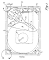
- Figure 1 is a top view of the disk drive assembly of the present invention.
- Figure 2 is a side view of the disk/shaft housing assembly of the present invention.
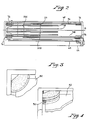
- Figure 3 is an expanded top view of a thermal isolator of the present invention.
- Figure 4 is a perspective view of the thermal isolator of Figure 4.
- Figure 5 is a perspective view of the disk drive housing assembly of the present invention.
- Figure 6 is a perspective view of the actuator motor assembly of the present invention.
- Figure 7 is a side view of the spindle motor assembly of the present invention.
- Figure 8 is a top view of an alternate embodiment of an isolator of the present invention.
- Figure 9 is a perspective view of the isolator of Figure 8.
- A disk drive which reduces the effect of differential thermal expansion to reduce or eliminate off tracking is described. In the following description, numerous specific details, such as number of disks, track pitch, etc., are set forth to provide a more thorough description of the present invention. It will be apparent, however, to one skilled in the art, that the present invention may be practiced without these specific details. In other instances, well known features have not been described in detail so as not to obscure the present invention.
- Referring generally to Figures 1 and 2, a top view and a side view respectively, of a disk drive assembly is shown, including
magnetic disks 18 and andactuator arm assembly 14. In the preferred embodiment of the present invention a plurality ofrigid disks 18 are arranged in a stack on aspindle 20. The disks are fixed to aspindle 20, which rotates aboutshaft 22. The spindle motor 11, (see Figure 7), is integral with the spindle assembly in the present preferred embodiment. Thedisks 18 are mounted onspindle 20 so that they are parallel to each other and arranged in a vertical stack. In the preferred embodiment, the disks are approximately 3 1/2 inches in diameter, and are made of aluminum coated with a magnetic coating, wherein both the upper and lower sided of the disks are used for data storage arranged in concentric data 'tracks' thereon. - The
actuator arm assembly 14, (see Figure 6), includes a plurality ofarm elements 16 pivotally mounted to a shaft 30. A voicecoil motor assembly 31 is mounted opposite thearm set 33, which enables the arm set to pivot about the shaft 30, as is well known in the art. The voice coil motor includes acenterpole 32, acoil 34 that surrounds the centerpole, and upper andlower magnet frames - Opposite the voice coil motor from the shaft and attached to the terminus of the arm elements are
flexures 48. Each flexure includes amagnetic head 50 mounted thereto, and mountingpad 54. The flexures are affixed to the arm elements using a ball suage which creates an interference fit when theball 46 is press-engaged inboss 44 to secure the flexure to the arm element via themounting plate 54. - Referring again to Figures 1 and 2, the thermally isolated HDA support structure of the present invention is illustrated. The HDA is substantially contained within a
housing 62 consisting ofcover 64 andbase 66. Thishousing 62 protects the HDA from thermal shock introduced by the outside environment. Thecover 64 dissipates heat throughout its entire surface area to reduce the gradient effects of a thermal shock. Thehousing 62 also provides a sealed environment for the HDA and in the present invention, is filled with dry nitrogen to reduce moisture and oxygen in the interior of thehousing 62. - The HDA itself is mounted within the
housing 62 by means of an HDA support structure so as to create a "box within a box" architecture to further protect the HDA from thermal variations. The HDA support structure consists of upper and lower mountingplates upper plate 56 andlower plate 58. The motor and actuator arm shaft assemblies are rigidly secured between the plates by means of a press fit into the plates which are located throughstandoffs 60 and the voice coil magnet frame. These plates are coupled to theouter housing 62 through means ofthermal isolators 76 disposed substantially at the interior corners of theouter housing 62. These thermal isolators prevent the transfer of heat to the HDA. In the preferred embodiment of the present invention, the isolators are comprised of rubber. However, any suitable thermally nonconductive material may be used without departing from the scope of the present invention. - Referring now to Figure 5, a perspective view of the drive housing, and its relationship to the internal, isolated HDA is shown. The HDA components are mounted on and between upper and
lower plates cover 64 andbase 66. Thecover 64 is substantially an inverted box which fits over the HDA and plates.Standoffs 60 mounted to the corners of and between the upper andlower plates cover 64 are slightly greater than the HDA/plate assembly so that the cover can receive the entire assembly. - Still referring to Figure 5 and also to Figures 3 and 4, the mounting of the
isolators 76 is shown. In the present preferred embodiment, the isolators are wedges of a resilient and insulative material, such as rubber. The isolators have aslot 80 for receiving thecorner regions 82 of the plates. The corners of the plates have arcuate corner portions for receivably engaging these slots of the isolators. The isolators provide thermal, as well as shock and vibration isolation of the HDA from the outside environment. The isolators are maintained in slight compression between the housing and the plates. Thus, the HDA, mounted toplates cover 64 and thebase 66, supported firmly within the housing against the corner regions of thecover 64 andbase 66. - Referring to Figures 8 and 9, an alternate embodiment of the isolators of the present invention is illustrated. In this embodiment, the interior corner of the
cover 64 includes a boss 81 to provide a mounting point for screws or other fastening devices to couple the base 66 to cover 64. Accordingly, theisolator 76A comprises an arcuate shape abuting the boss 81 such that theisolator 76A has an interior andexterior radius isolator 76A of this embodiment is substantially "L" shaped in cross section as shown by extendingmember 83 which extends alongedge 91 ofcorner 82. Theisolator 76A still provides a press fit between thecover 64 and theplates - Referring again to Figure 2, the printed
circuit board 68 containing the operative electronic components for the drive is mounted below the base. To prevent the heat generating components of the printed circuit board from creating temperature gradients in the HDA, the printedcircuit board 68 is mounted beneathbase 66. Thus,base 66 acts as a barrier to thermal shocks from printedcircuit board 68. Further, any temperature gradients generated by the printedcircuit board 68 will be evenly dissipated by thebase 66 andcover 64, resulting in a more uniform temperature profile in the HDA. Aconnector 70 provides for electrical connection to the spindle motor of the HDA viaflexible circuit 72. A secondflexible circuit 78 provides electrical connection to the actuator assembly. - The present inventive drive design provides a thermal circuit for the HDA that is substantially symmetrical above and below the
centerplane 10 that bisects the HDA. To accomplish this, the main drive components typically subject to temperature transients that can result in off-tracking, namely the HDA, are specifically designed to be thermally balanced about the bisecting centerplane such that heat introduced in those components is transferred with a balanced profile that is substantially matched above and below thecenterplane 10. - The actuator motor is made of components that substantially mirror each other above and below the
centerplane 10. Thus as seen in Figure 6, the actuator motor includes two opposing, matched magnet frames 36 and 38 having substantially the same dimensions and made of same materials. Similarly, the centerpole and coil have the same cross section above and below thecenterplane 10. Likewise, the arm set 33 is uniform in cross section above and below the centerplane, as are theflexures 48. Likewise, the shaft is symmetrical about thecenterplane 10. - Referring now to the spindle assembly of Figure 7, the
disks 18 mounted thereon are spaced equally apart and matched in their position and number above and below thetransverse centerplane 10 of the HDA. The other components of the spindle assembly that provide the primary thermally conductive paths for the transfer of heat away from the spindle motor are substantially matched in dimension, material and location above and below the centerplane of the HDA to provide symmetrical and uniform heat transfer above and below the centerplane. Thus, the disk drive in the present configuration maintains a substantially uniform temperature profile and thermal inertia above and below thecenterplane 10. - Referring again to Figure 5, the motor shaft and actuator arm assembly shaft are both symmetrical about the centerplane. Further, the shafts and plates are constructed of materials having the same coefficient of thermal expansion. In the preferred embodiment of the present invention, these components are comprised of steel. However, other thermally matched components may be utilized as well without departing from the scope of the present invention.
- Power is dissipated in the spindle motor via the windings of the stator, and in the actuator, via the voice coil. This power dissipation can generate temperature gradients which can affect drive performance and lead to off tracking errors. Therefore, both the motor windings and voice coil windings are disposed symmetrically about both sides of the centerplane such that heat is dissipated uniformly through the shafts and associated components above and below the centerplane.
- In the present case, the motor is symmetrical with regards to its substantially thermally conductive components about the center plane. The motor is illustrated in Figure 7. A disk stack consisting of
disks 18 andspacers 19, both preferably comprised of aluminum, are mounted onspindle 20 such that the bottom most disk rests onflange 23.Spindle 20 is comprised ofspindle hub 25 and bearing sleeve 27, also comprised of aluminum in the preferred embodiment. By making the motor out of thermally matched parts, such as aluminum, thermal distortions and misalignments are substantially eliminated. The motor of the present invention also includes a ferromagnetic flux sleeve 29, comprised of low carbon steel for example, to provide a flux path for themotor magnets 45. The motor assembly is coupled to thestator shaft 35 throughbearings 37. - During drive operation, heat is generated from the spindle motor, the rotation of the disks, from the printed
circuit board 68, and from the actuator motor. That heat is transferred in accordance with the present invention uniformly and at the same rate above and below theHDA centerplane 10. In operation, the external housing, when subject to thermal shock, will dissipate the heat throughout the housing. If the internal environment of the drive undergoes some temperature increase, the heat therein will be distributed uniformly among the thermally matched HDA components. Further, theisolators 76 will isolate the HDA from thermal shock. The heat generated by the internal components is ultimately transmitted through thespindle shaft 20 above and below the centerplane to the plates in a uniform manner, and to the other thermally matched components above and below the centerplane. - Because the thermal profile of the HDA is uniform, spacing differentials between the servo disk and the data disks caused by thermal expansion are kept within very close tolerances, on the order of approximately ± 50 microinches. Therefore, high track densities can be achieved while still utilizing a dedicated servo configuration. In the preferred embodiment of the present invention, a track density of approximately 1600-200 tpi is achieved.
- Thus, a disk drive which is substantially independent of thermal variations is described.
Claims (7)
- A disk drive system comprising:
a housing (62) having a cover (64) coupled to a base (66);
a head disk assembly (HDA) including a spindle motor assembly for mounting disks (18), an actuator arm assembly (14) for mounting read/write heads (50); and
an HDA support structure including a top plate (56) and a bottom plate (58) coupled to said HDA for positioning and retaining said HDA;
said disk drive system characterized in that
said head disk assembly (HDA) includes a plurality of disks (18) mounted on said spindle motor assembly;
said top plate (56) and said bottom plate (58) have a plurality of thermal isolators (76) coupled thereto; and
said HDA support structure is disposed within the interior of said housing with said isolators (76) abuting said housing (64) and being disposed between said housing and said top and bottom plates respectively such that said HDA and said top and bottom plates are out of direct contact with said housing whereby said HDA is substantially thermally isolated from said housing. - The system of claim 1 wherein said isolators (76) comprise a thermally nonconductive, resilient material.
- The system of claim 2 wherein said isolators (76) comprise rubber.
- The system of claim 1 further including a control board (68) including electronic circuitry for controlling said system disposed beneath and coupled to said base (66) such that thermal gradients generated by said board are dissipated by said base.
- The system of claim 1 wherein said HDA is disposed such that it is symmetrical about a center plane (10) perpendicular to and bisecting the spindle (20) of said spindle motor assembly.
- The system of claim 1 wherein said housing (62) is sealed and filled with nitrogen to reduce moisture and oxygen in the interior of said housing (62).
- The system of claim 1 wherein said spindle motor assembly comprises an in-spindle motor assembly.
Applications Claiming Priority (3)
| Application Number | Priority Date | Filing Date | Title |
|---|---|---|---|
| US07/270,717 US4980786A (en) | 1988-11-14 | 1988-11-14 | Method and apparatus for improved thermal isolation and stability of disk drives |
| US270717 | 1988-11-14 | ||
| PCT/US1989/005032 WO1990005982A1 (en) | 1988-11-14 | 1989-11-07 | Method and apparatus for improved thermal isolation and stability of disk drives |
Publications (3)
| Publication Number | Publication Date |
|---|---|
| EP0447412A1 EP0447412A1 (en) | 1991-09-25 |
| EP0447412A4 EP0447412A4 (en) | 1992-12-02 |
| EP0447412B1 true EP0447412B1 (en) | 1995-09-06 |
Family
ID=23032498
Family Applications (1)
| Application Number | Title | Priority Date | Filing Date |
|---|---|---|---|
| EP89912912A Expired - Lifetime EP0447412B1 (en) | 1988-11-14 | 1989-11-07 | Method and apparatus for improved thermal isolation and stability of disk drives |
Country Status (7)
| Country | Link |
|---|---|
| US (1) | US4980786A (en) |
| EP (1) | EP0447412B1 (en) |
| JP (1) | JP2696428B2 (en) |
| AT (1) | ATE127610T1 (en) |
| AU (1) | AU4626689A (en) |
| DE (1) | DE68924172T2 (en) |
| WO (1) | WO1990005982A1 (en) |
Families Citing this family (42)
| Publication number | Priority date | Publication date | Assignee | Title |
|---|---|---|---|---|
| US5029027A (en) * | 1989-11-13 | 1991-07-02 | Hewlett-Packard Company | Thermally predictable disk drive mechanism |
| ES2090122T3 (en) * | 1990-01-08 | 1996-10-16 | Ibm | FILE ON DISC THAT INCLUDES MEANS TO GUARANTEE DISC / CUBE CONCENTRICITY. |
| JPH04195988A (en) * | 1990-11-28 | 1992-07-15 | Nikon Corp | Driving device for optical method information medium |
| US5875067A (en) * | 1991-03-22 | 1999-02-23 | Seagate Technology, Inc. | Acoustic isolator for a disc drive assembly |
| US5251085A (en) * | 1991-07-17 | 1993-10-05 | Maxtor Corporation | Pivotable arm assembly with reduced thermal distortion |
| AU4086993A (en) * | 1992-06-03 | 1993-12-30 | Anembo Limited | Apparatus for damping the transmission of audible noise generated by a disc drive |
| US6002546A (en) * | 1993-02-10 | 1999-12-14 | Fujitsu Limited | Magnetic disk apparatus with visco elastic shock dampening |
| US5414574A (en) * | 1993-07-29 | 1995-05-09 | International Business Machines Corporation | Hybrid base for ultrathin disk drives |
| EP0647942A1 (en) * | 1993-10-12 | 1995-04-12 | Hewlett-Packard Company | Disk drive with inverted base and method for its assembly |
| JP3087809B2 (en) * | 1994-01-14 | 2000-09-11 | 富士通株式会社 | Frame structure for disk drive |
| JP3493750B2 (en) * | 1994-10-06 | 2004-02-03 | 株式会社日立製作所 | Magnetic disk drive |
| JPH1050045A (en) * | 1996-07-26 | 1998-02-20 | Yamaha Corp | Wiring structure for disk drive device |
| US5781373A (en) * | 1997-03-14 | 1998-07-14 | Western Digital Corporation | Acoustic noise reduction system for a disk drive |
| JP3991390B2 (en) * | 1997-05-30 | 2007-10-17 | 富士通株式会社 | Storage device |
| EP0948763B1 (en) | 1997-07-31 | 2003-12-17 | Fujitsu Limited | Shock mount for hard disk drive in a portable computer |
| JP4105309B2 (en) | 1997-11-06 | 2008-06-25 | 富士通株式会社 | Electronic device and mounting mechanism |
| US6034841A (en) * | 1998-05-29 | 2000-03-07 | International Business Machines Corporation | Disk drive with composite sheet metal and encapsulated plastic base |
| EP1035547B1 (en) * | 1998-09-29 | 2004-11-24 | Mitsubishi Denki Kabushiki Kaisha | Corner part reinforcing device of disc device chassis |
| US6320744B1 (en) | 1999-02-19 | 2001-11-20 | General Dynamics Information Systesm, Inc. | Data storage housing |
| US6158833A (en) * | 1999-09-11 | 2000-12-12 | Schwab Corporation | Fire-resistant computer storage apparatus |
| US6999909B1 (en) | 1999-10-28 | 2006-02-14 | Seagate Technology Llc | Process for designing an optimal vibration isolation mount for a disc drive |
| JP4199908B2 (en) * | 2000-01-13 | 2008-12-24 | 株式会社日立グローバルストレージテクノロジーズ | Magnetic disk device characterized by cable wiring and electronic device using the same |
| JP2002245749A (en) * | 2001-02-21 | 2002-08-30 | Fujitsu Ltd | Disk device and information processor |
| US6671124B2 (en) * | 2001-09-07 | 2003-12-30 | Lockheed Martin Corporation | Shock and vibration system |
| US7106541B2 (en) * | 2001-09-14 | 2006-09-12 | Convergent Systems Solutions, Llc | Digital device configuration and method |
| US6973535B2 (en) | 2001-09-14 | 2005-12-06 | Cornice, Inc. | Digital device configuration and method |
| US6791799B2 (en) | 2001-09-14 | 2004-09-14 | Convergent Systems Solutions Llc | Digital device configuration and method |
| US7162578B2 (en) * | 2001-09-14 | 2007-01-09 | Cornice, Inc. | Digital device configuration and method |
| US6831830B2 (en) * | 2002-03-20 | 2004-12-14 | Convergent Systems Solutions, Llc | Digital storage element in a host device and method |
| US7218473B2 (en) * | 2002-03-22 | 2007-05-15 | Seagate Technology Llc | Two-stage sealing of a data storage assembly housing to retain a low density atmosphere |
| US6791789B2 (en) * | 2002-12-12 | 2004-09-14 | Quantum Corporation | Thermal insulator for protecting a storage tape in a tape drive |
| US9293169B2 (en) | 2004-05-04 | 2016-03-22 | Seagate Technology Llc | Seal-type label to contain pressurized gas environment |
| US20050259352A1 (en) * | 2004-05-19 | 2005-11-24 | Leclair Stephen P | Bumper device for data storage apparatus |
| TWI261743B (en) * | 2004-08-02 | 2006-09-11 | Asustek Comp Inc | Dynamic absorber system and notebook computer utilizing the same |
| US7916487B2 (en) * | 2005-03-30 | 2011-03-29 | Yosef Bitton | Method and apparatus for the enhanced disaster survivability of a networked computer server |
| US7508682B2 (en) * | 2005-09-19 | 2009-03-24 | Hitachi, Ltd. | Housing for an electronic circuit |
| US20070219747A1 (en) * | 2006-03-07 | 2007-09-20 | Hughes James E | HDD throttle polling based on blade temperature |
| US20080203081A1 (en) * | 2006-12-01 | 2008-08-28 | Honeywell International Inc. | Variable thermal resistor system |
| JP2010225207A (en) * | 2009-03-19 | 2010-10-07 | Alphana Technology Co Ltd | Disk drive device |
| US8331084B2 (en) * | 2010-05-13 | 2012-12-11 | General Electric Company | Apparatus for securing electronic equipment |
| KR20130015889A (en) * | 2011-08-05 | 2013-02-14 | 삼성전기주식회사 | Base for motor and hard disk drive including the same |
| US20220187567A1 (en) * | 2020-12-15 | 2022-06-16 | Plx, Inc. | Mount for an optical structure and method of mounting the optical structure to the mount |
Family Cites Families (12)
| Publication number | Priority date | Publication date | Assignee | Title |
|---|---|---|---|---|
| US3577133A (en) * | 1968-11-19 | 1971-05-04 | Engineered Data Peripherals Co | Disc memory system including unitary support member and printed circuit board |
| US3912278A (en) * | 1974-07-22 | 1975-10-14 | Int Memory Systems | Disk drive assembly |
| DE2905414B1 (en) * | 1979-02-10 | 1980-04-24 | Cpt Comp Peripherie Technik Gm | Magnetic disk storage |
| US4367503A (en) * | 1980-12-24 | 1983-01-04 | International Business Machines Corporation | Fermetically sealed disk file |
| DE3209243A1 (en) * | 1982-03-13 | 1983-09-15 | Philips Patentverwaltung Gmbh, 2000 Hamburg | POSITIONING DEVICE FOR THE MAGNET HEAD OF A DISK-SHAPED MAGNETIC STORAGE |
| US4553183A (en) * | 1982-06-28 | 1985-11-12 | Atasi Corporation | Memory storage apparatus having improved housing and base plate arrangement |
| JPS59132459A (en) * | 1983-01-20 | 1984-07-30 | Toshiba Corp | Magnetic disk device |
| US4620248A (en) * | 1984-09-04 | 1986-10-28 | Magnetic Peripherals Inc. | Apparatus for controlling humidity in a disk drive |
| US4556969A (en) * | 1984-12-28 | 1985-12-03 | International Business Machines Corporation | Hermetically sealed disk file |
| US4831476A (en) * | 1985-07-15 | 1989-05-16 | Allen-Bradley Company | Disc drive isolation system |
| US4705257A (en) * | 1987-03-23 | 1987-11-10 | Digital Equipment Corporation | Shock and vibration isolation mounting |
| US4908715A (en) * | 1988-03-29 | 1990-03-13 | Magnetic Peripherals Inc. | Disk drive unit |
-
1988
- 1988-11-14 US US07/270,717 patent/US4980786A/en not_active Expired - Lifetime
-
1989
- 1989-11-07 DE DE68924172T patent/DE68924172T2/en not_active Expired - Fee Related
- 1989-11-07 AT AT89912912T patent/ATE127610T1/en not_active IP Right Cessation
- 1989-11-07 JP JP2500394A patent/JP2696428B2/en not_active Expired - Lifetime
- 1989-11-07 AU AU46266/89A patent/AU4626689A/en not_active Abandoned
- 1989-11-07 WO PCT/US1989/005032 patent/WO1990005982A1/en active IP Right Grant
- 1989-11-07 EP EP89912912A patent/EP0447412B1/en not_active Expired - Lifetime
Also Published As
| Publication number | Publication date |
|---|---|
| EP0447412A4 (en) | 1992-12-02 |
| DE68924172T2 (en) | 1996-05-15 |
| ATE127610T1 (en) | 1995-09-15 |
| AU4626689A (en) | 1990-06-12 |
| DE68924172D1 (en) | 1995-10-12 |
| JPH04502977A (en) | 1992-05-28 |
| US4980786A (en) | 1990-12-25 |
| EP0447412A1 (en) | 1991-09-25 |
| JP2696428B2 (en) | 1998-01-14 |
| WO1990005982A1 (en) | 1990-05-31 |
Similar Documents
| Publication | Publication Date | Title |
|---|---|---|
| EP0447412B1 (en) | Method and apparatus for improved thermal isolation and stability of disk drives | |
| US5587855A (en) | Supporting device for minimizing vibration, noise and external impact of a hard disk drive | |
| EP0427490B1 (en) | Disk drive apparatus | |
| EP0484433B1 (en) | Architecture for 2-1/2 inch diameter single disk drive | |
| US6429999B1 (en) | Pre-assembled voice coil magnetic assembly and rotatable attachment structure/method to base plate for disc drive | |
| US4553183A (en) | Memory storage apparatus having improved housing and base plate arrangement | |
| US4491888A (en) | Memory storage apparatus having vibration-dampened base plate arrangement | |
| US4890176A (en) | Crash stop and magnetic latch for a voice coil actuator | |
| EP0556287B1 (en) | High performance disk drive architecture | |
| US4190870A (en) | Disk drive assembly | |
| US5224000A (en) | Crash stop and magnetic latch for a voice coil actuator | |
| JPS6394492A (en) | Large-capacity digital recorder | |
| US4947274A (en) | Resiliently mounted crash stop and magnetic latch for a voice coil actuator | |
| KR19990023166A (en) | Apparatus and method for improving cooling of coils for voice coil motors in hard disks | |
| US6867963B2 (en) | Disc drive mounting system including vibration isolator and heat sink | |
| US5060095A (en) | Head-disk enclosure assembly for a magnetic disk storage device | |
| US6510021B1 (en) | Mechanical isolation for a disc drive spindle motor | |
| JPH04265589A (en) | Compact disk drive | |
| EP0538260B1 (en) | Low height disk drive | |
| US5621582A (en) | Disk drive including a baseplate well for the spin motor | |
| JPH02166683A (en) | Magnetic disk device | |
| JPH11219573A (en) | Vibration damping system and servowriter | |
| JP3028252B2 (en) | Magnetic disk drive |
Legal Events
| Date | Code | Title | Description |
|---|---|---|---|
| PUAI | Public reference made under article 153(3) epc to a published international application that has entered the european phase |
Free format text: ORIGINAL CODE: 0009012 |
|
| 17P | Request for examination filed |
Effective date: 19910608 |
|
| AK | Designated contracting states |
Kind code of ref document: A1 Designated state(s): AT BE CH DE FR GB IT LI LU NL SE |
|
| A4 | Supplementary search report drawn up and despatched |
Effective date: 19921012 |
|
| AK | Designated contracting states |
Kind code of ref document: A4 Designated state(s): AT BE CH DE FR GB IT LI LU NL SE |
|
| 17Q | First examination report despatched |
Effective date: 19940103 |
|
| GRAA | (expected) grant |
Free format text: ORIGINAL CODE: 0009210 |
|
| AK | Designated contracting states |
Kind code of ref document: B1 Designated state(s): AT BE CH DE FR GB IT LI LU NL SE |
|
| PG25 | Lapsed in a contracting state [announced via postgrant information from national office to epo] |
Ref country code: NL Free format text: LAPSE BECAUSE OF NON-PAYMENT OF DUE FEES Effective date: 19950906 Ref country code: BE Effective date: 19950906 Ref country code: AT Effective date: 19950906 |
|
| REF | Corresponds to: |
Ref document number: 127610 Country of ref document: AT Date of ref document: 19950915 Kind code of ref document: T |
|
| REF | Corresponds to: |
Ref document number: 68924172 Country of ref document: DE Date of ref document: 19951012 |
|
| PG25 | Lapsed in a contracting state [announced via postgrant information from national office to epo] |
Ref country code: LU Free format text: LAPSE BECAUSE OF NON-PAYMENT OF DUE FEES Effective date: 19951130 |
|
| PGFP | Annual fee paid to national office [announced via postgrant information from national office to epo] |
Ref country code: CH Payment date: 19951130 Year of fee payment: 7 |
|
| ITF | It: translation for a ep patent filed |
Owner name: STUDIO TORTA SOCIETA' SEMPLICE |
|
| PG25 | Lapsed in a contracting state [announced via postgrant information from national office to epo] |
Ref country code: SE Effective date: 19951206 |
|
| NLV1 | Nl: lapsed or annulled due to failure to fulfill the requirements of art. 29p and 29m of the patents act | ||
| EN | Fr: translation not filed | ||
| REG | Reference to a national code |
Ref country code: CH Ref legal event code: PL |
|
| PLBE | No opposition filed within time limit |
Free format text: ORIGINAL CODE: 0009261 |
|
| STAA | Information on the status of an ep patent application or granted ep patent |
Free format text: STATUS: NO OPPOSITION FILED WITHIN TIME LIMIT |
|
| ET | Fr: translation filed | ||
| 26N | No opposition filed | ||
| REG | Reference to a national code |
Ref country code: FR Ref legal event code: RN Ref country code: FR Ref legal event code: FC |
|
| PG25 | Lapsed in a contracting state [announced via postgrant information from national office to epo] |
Ref country code: LI Free format text: LAPSE BECAUSE OF FAILURE TO SUBMIT A TRANSLATION OF THE DESCRIPTION OR TO PAY THE FEE WITHIN THE PRESCRIBED TIME-LIMIT Effective date: 19961130 Ref country code: CH Free format text: LAPSE BECAUSE OF FAILURE TO SUBMIT A TRANSLATION OF THE DESCRIPTION OR TO PAY THE FEE WITHIN THE PRESCRIBED TIME-LIMIT Effective date: 19961130 |
|
| PGFP | Annual fee paid to national office [announced via postgrant information from national office to epo] |
Ref country code: FR Payment date: 19981110 Year of fee payment: 10 |
|
| PGFP | Annual fee paid to national office [announced via postgrant information from national office to epo] |
Ref country code: GB Payment date: 19981113 Year of fee payment: 10 |
|
| PGFP | Annual fee paid to national office [announced via postgrant information from national office to epo] |
Ref country code: DE Payment date: 19981116 Year of fee payment: 10 |
|
| PG25 | Lapsed in a contracting state [announced via postgrant information from national office to epo] |
Ref country code: GB Free format text: LAPSE BECAUSE OF NON-PAYMENT OF DUE FEES Effective date: 19991107 |
|
| GBPC | Gb: european patent ceased through non-payment of renewal fee |
Effective date: 19991107 |
|
| PG25 | Lapsed in a contracting state [announced via postgrant information from national office to epo] |
Ref country code: FR Free format text: LAPSE BECAUSE OF NON-PAYMENT OF DUE FEES Effective date: 20000731 |
|
| PG25 | Lapsed in a contracting state [announced via postgrant information from national office to epo] |
Ref country code: DE Free format text: LAPSE BECAUSE OF NON-PAYMENT OF DUE FEES Effective date: 20000901 |
|
| REG | Reference to a national code |
Ref country code: FR Ref legal event code: ST |
|
| PG25 | Lapsed in a contracting state [announced via postgrant information from national office to epo] |
Ref country code: IT Free format text: LAPSE BECAUSE OF NON-PAYMENT OF DUE FEES;WARNING: LAPSES OF ITALIAN PATENTS WITH EFFECTIVE DATE BEFORE 2007 MAY HAVE OCCURRED AT ANY TIME BEFORE 2007. THE CORRECT EFFECTIVE DATE MAY BE DIFFERENT FROM THE ONE RECORDED. Effective date: 20051107 |