EP0447061A2 - Image intensifiers - Google Patents
Image intensifiers Download PDFInfo
- Publication number
- EP0447061A2 EP0447061A2 EP91301568A EP91301568A EP0447061A2 EP 0447061 A2 EP0447061 A2 EP 0447061A2 EP 91301568 A EP91301568 A EP 91301568A EP 91301568 A EP91301568 A EP 91301568A EP 0447061 A2 EP0447061 A2 EP 0447061A2
- Authority
- EP
- European Patent Office
- Prior art keywords
- power supply
- image intensifier
- image
- enabled
- period
- Prior art date
- Legal status (The legal status is an assumption and is not a legal conclusion. Google has not performed a legal analysis and makes no representation as to the accuracy of the status listed.)
- Withdrawn
Links
- 230000003287 optical effect Effects 0.000 claims description 6
- 230000000694 effects Effects 0.000 abstract description 3
- OAICVXFJPJFONN-UHFFFAOYSA-N Phosphorus Chemical compound [P] OAICVXFJPJFONN-UHFFFAOYSA-N 0.000 description 5
- 230000008878 coupling Effects 0.000 description 5
- 238000010168 coupling process Methods 0.000 description 5
- 238000005859 coupling reaction Methods 0.000 description 5
- 238000000034 method Methods 0.000 description 5
- 238000010586 diagram Methods 0.000 description 4
- 230000004048 modification Effects 0.000 description 3
- 238000012986 modification Methods 0.000 description 3
- 230000002688 persistence Effects 0.000 description 3
- 238000006243 chemical reaction Methods 0.000 description 2
- 230000010355 oscillation Effects 0.000 description 2
- 230000035945 sensitivity Effects 0.000 description 2
- 230000015556 catabolic process Effects 0.000 description 1
- 239000002131 composite material Substances 0.000 description 1
- 239000004020 conductor Substances 0.000 description 1
- 238000006731 degradation reaction Methods 0.000 description 1
- 230000005684 electric field Effects 0.000 description 1
- 230000006870 function Effects 0.000 description 1
- 238000003384 imaging method Methods 0.000 description 1
- 230000001939 inductive effect Effects 0.000 description 1
- 230000002401 inhibitory effect Effects 0.000 description 1
- 230000005764 inhibitory process Effects 0.000 description 1
- 230000010354 integration Effects 0.000 description 1
- 230000008447 perception Effects 0.000 description 1
- 230000005855 radiation Effects 0.000 description 1
- 238000012216 screening Methods 0.000 description 1
- 230000000007 visual effect Effects 0.000 description 1
Images


Classifications
-
- H—ELECTRICITY
- H01—ELECTRIC ELEMENTS
- H01J—ELECTRIC DISCHARGE TUBES OR DISCHARGE LAMPS
- H01J29/00—Details of cathode-ray tubes or of electron-beam tubes of the types covered by group H01J31/00
- H01J29/98—Circuit arrangements not adapted to a particular application of the tube and not otherwise provided for
-
- H—ELECTRICITY
- H04—ELECTRIC COMMUNICATION TECHNIQUE
- H04N—PICTORIAL COMMUNICATION, e.g. TELEVISION
- H04N23/00—Cameras or camera modules comprising electronic image sensors; Control thereof
- H04N23/70—Circuitry for compensating brightness variation in the scene
- H04N23/75—Circuitry for compensating brightness variation in the scene by influencing optical camera components
-
- H—ELECTRICITY
- H01—ELECTRIC ELEMENTS
- H01J—ELECTRIC DISCHARGE TUBES OR DISCHARGE LAMPS
- H01J31/00—Cathode ray tubes; Electron beam tubes
- H01J31/08—Cathode ray tubes; Electron beam tubes having a screen on or from which an image or pattern is formed, picked up, converted, or stored
- H01J31/50—Image-conversion or image-amplification tubes, i.e. having optical, X-ray, or analogous input, and optical output
-
- H—ELECTRICITY
- H04—ELECTRIC COMMUNICATION TECHNIQUE
- H04N—PICTORIAL COMMUNICATION, e.g. TELEVISION
- H04N23/00—Cameras or camera modules comprising electronic image sensors; Control thereof
- H04N23/50—Constructional details
- H04N23/55—Optical parts specially adapted for electronic image sensors; Mounting thereof
-
- H—ELECTRICITY
- H05—ELECTRIC TECHNIQUES NOT OTHERWISE PROVIDED FOR
- H05G—X-RAY TECHNIQUE
- H05G1/00—X-ray apparatus involving X-ray tubes; Circuits therefor
- H05G1/08—Electrical details
- H05G1/64—Circuit arrangements for X-ray apparatus incorporating image intensifiers
-
- H—ELECTRICITY
- H01—ELECTRIC ELEMENTS
- H01J—ELECTRIC DISCHARGE TUBES OR DISCHARGE LAMPS
- H01J2231/00—Cathode ray tubes or electron beam tubes
- H01J2231/50—Imaging and conversion tubes
- H01J2231/50057—Imaging and conversion tubes characterised by form of output stage
- H01J2231/50063—Optical
-
- H—ELECTRICITY
- H01—ELECTRIC ELEMENTS
- H01J—ELECTRIC DISCHARGE TUBES OR DISCHARGE LAMPS
- H01J2231/00—Cathode ray tubes or electron beam tubes
- H01J2231/50—Imaging and conversion tubes
- H01J2231/50057—Imaging and conversion tubes characterised by form of output stage
- H01J2231/50089—Having optical stage before electrical conversion
- H01J2231/50094—Charge coupled device [CCD]
Definitions
- This invention relates to image intensifiers, in particular image intensifiers utilising a high operating voltage but which are energised from a low voltage power source by means of dc to dc converters.
- an image intensifier apparatus utilising a high operating voltage, includes a power supply for producing the voltage operable in an intermittent manner such that the power supply is enabled for a period which is much less than the period for which it is inhibited.
- the eye if the eye is viewing the phosphor directly, then it will be looking at the less sharp image for the 5% of the time that the converter is operating, but for 95% of the time it will be looking at the sharper image obtained when the converter is not operating.
- the combination of phosphor persistence and visual persistence will result in the perception of a picture which is the weighted average of the sharper and less sharp images. Because the weighting is strongly biased towards the sharper image the eye will see a picture which is very nearly as good as if the intensifier was not influenced by the magnetic field from the converter.
- the converter may be enabled for slightly longer than the field blanking period t2.
- the first few lines preceding and/or following the field blanking period will be susceptible to interference from the converter oscillator. However, this may not be objectionable, especially if the camera is used in conjunction with an overscanned monitor when the affected lines will not be visible to the viewer.
Landscapes
- Engineering & Computer Science (AREA)
- Multimedia (AREA)
- Signal Processing (AREA)
- Transforming Light Signals Into Electric Signals (AREA)
- Studio Devices (AREA)
- Image-Pickup Tubes, Image-Amplification Tubes, And Storage Tubes (AREA)
Abstract
The high voltage power supply (2) of an image intensifier (3) is operated intermittently to minimise the effect on the intensified image of interference produced by the power supply (2), the input capacitance of the intensifier maintaining the high voltage at an acceptable level when the power supply (2) is not operating.
When used in conjunction with a video camera, the power supply (2) may be allowed to operate only during the frame synch and/or line synch periods. A shutter may inhibit operation of the image intensifier (3) whilst its power supply is operating.
Description
- This invention relates to image intensifiers, in particular image intensifiers utilising a high operating voltage but which are energised from a low voltage power source by means of dc to dc converters.
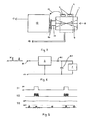
- Image intensifiers usually require high voltages, typically 10 kV or more to make them operate. To allow them to be used with batteries or other low-voltage power sources, it is common to use a power supply comprising a dc to dc converter which accepts a low input voltage, for example 2.5 to 3 volts, and delivers the higher voltage, typically 10kV or more, required by the image intensifier. Because of size restraints it has been proposed to construct the converter in the form known as a wrap around' power supply, that is to say the converter circuitry surrounds and is potted in the same cylindrical case as the intensifier. Such an arrangement is illustrated in Figure 1, and comprises a
cylindrical case 1, a wrap around'converter power supply 2, and anintensifier 3. As well as being compact, this arrangement allows the lead lengths of high voltage-carrying conductors to be kept to a minimum, which enhances safety. - Figure 2 shows in diagrammatic form the operation of a simple image intensifier. The
intensifier 3 is energised by apower supply 10, which generally comprises a dc to dc converter including an intermediate ac stage. Light 4 from an image-producing source, (not shown), produces an image on the photo-cathode 8. Electrons emitted from the photo-cathode are accelerated alongpaths 9 in an electric field and are focused by means offocus electrodes 7 so as to produce an image on aphosphor 6. The image so produced is an amplified version of the image on the photo-cathode 8, and can be viewed by the eye of an observer or further optical apparatus such as a video camera, (not shown), at 5. - However, a number of problems have been encountered with this arrangement. The first is that the varying magnetic field from the inductive components of the converter will tend to modulate the paths of the electrons inside the intensifier. Hence electrons from any particular point on the photo-cathode will not always impinge on the corresponding point of the anode phosphor, resulting in an image with reduced sharpness.
- The second problem arises when the intensifier is used in conjunction with some form of electronic imaging system, when interference from the intensifier power supply can cause objectionable interference in the TV picture.
- Prior art solutions to these problems have involved magnetic and electrical screening, but these techniques can be expensive to implement, making assembly more difficult and adding significantly to the cost and size of the system.
- The present invention has arisen in an attempt to eliminate or reduce the effects of the disadvantages of the prior art.
- In accordance with the invention, an image intensifier apparatus utilising a high operating voltage, includes a power supply for producing the voltage operable in an intermittent manner such that the power supply is enabled for a period which is much less than the period for which it is inhibited.
- The apparatus may include an optical shutter or an electrical arrangement to inhibit operation of the image intensifier while the power supply is enabled. The apparatus may include a video camera such as a CCD video camera, the power supply only being allowed to operate during the frame blanking and/or line blanking periods of the camera. The power supply may be a dc to dc converter.
- As the current drain by the image intensifier is relatively small, the capacitance is sufficient to maintain the output voltage at an acceptable value during period in which the power supply is turned off.
- The invention will now be described with reference to the accompanying drawings in which:
- Figure 1 shows in schematic form an image intensifier module;
- Figure 2 shows in diagrammatic form the idealised operation of a simple image intensifier;
- Figure 3 shows an image intensifier apparatus incorporating a CCD video camera;
- Figure 4 shows a block diagram of an image intensifier apparatus in accordance with the invention;
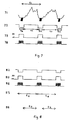
- Figure 5 shows a waveform diagram illustrating the operation of apparatus in accordance with the invention.
- Figure 6 shows an image intensifier apparatus in accordance with the invention; and
- Figures 7 and 8 shows waveform diagrams illustrating the operation of apparatus in accordance with the invention.
- A first embodiment of the invention will now be described with reference to Figures 3, 4 and 5. In Figure 3, a
video camera 12 has animager 16, for example a CCD imager which is coupled to the amplified image produced by theimage intensifier 1 via anoptical coupling 15. Thepower supply 2 of theimage intensifier 1 comprises a dc to dc converter having an inverter to convert the low voltage dc input to high frequency ac which is transformed and rectified, possibly by means of a voltage multiplier, to produce the high voltage dc output. The power supply includes one or more transformers 11. When the power supply is operating, magnetic coupling from the transformers 11 can give rise to spurious modulation of theelectron paths 9 within the intensifier, while coupling 13 by radiation between the transformers 11 and sensitive video processing circuitry within thevideo camera 12 can give rise to interference in the video signals. If thecamera 12 andimage intensifier 1 share a common power supply, a further coupling path for interference between the converter and the camera exists via the power supply leads 14. This video signal interference typically results in a TV picture having diagonal lines or bands, which can be quite objectionable. In accordance with the invention, the input power supply is not applied continuously, but, as shown in Figures 4 and 5, is repetitively pulsed on and off. In Figure 5, 51 shows the pulsed input voltage applied toterminal 41 of Figure 4, 52 represents the oscillations which are produced within the dc to dc converter as a consequence of the dc to dc voltage conversion, 53 shows the variation of the output voltage onterminal 42. In operation, it is arranged that the converter ON period B, is much shorter than its OFF period A. Although the converter is only producing a high voltage output for a small proportion of the total time, thecapacitance 43 at theoutput terminal 42 of the converter due to the converter output capacitance and the intensifier input capacitance, is generally sufficient to maintain the high voltage at an acceptable level during the periods when the converter is not operating. For example, the on time A may be 1mS and the OFF time B 19mS: these times are given by way of example only for the purpose of explaining the operation of the invention and are not intended to limit the scope of the invention. - In this example if the eye is viewing the phosphor directly, then it will be looking at the less sharp image for the 5% of the time that the converter is operating, but for 95% of the time it will be looking at the sharper image obtained when the converter is not operating. The combination of phosphor persistence and visual persistence will result in the perception of a picture which is the weighted average of the sharper and less sharp images. Because the weighting is strongly biased towards the sharper image the eye will see a picture which is very nearly as good as if the intensifier was not influenced by the magnetic field from the converter.
- While this embodiment has been described as operating by pulsing the low voltage power supply, the invention is not limited to this arrangement. For example, the low voltage power supply could be left continuously connected, the converter being provided with an internal or external gating arrangement to turn it on and off in the manner described.
- A second embodiment of the invention, will now be described with reference to Figures 3 and 7.
- As has been previously described, in the arrangement of Figure 3, the video camera suffers from interference from the dc-dc converter when the converter operates continuously. In the second embodiment of the invention, the
converter 2 of theimage intensifier 1 is only allowed to operate during the field blanking period. Figure 7 shows a waveform diagram illustrating the operation of the arrangement of Figure 3 in accordance with the invention. In Figure 7, 71 represents a composite video signal in which t1 denotes the duration of one complete field. In a CCIR 50Hz video standard, the field rate is 20mS. Note that, for clarity, the line synch pulses are not shown in 71. 72 represents the field blanking pulses. Each blanking pulse has a duration t2, during which time the field is blanked. In the CCIR 50Hz system, t2 = 1.6mS. 73 represents the input voltage to theconverter 2. 74 represents the oscillating voltage developed in theconverter 2 during conversion. It is evident from Figure 7 that, as oscillations only occur during the field blanking period t2, they will not cause interference in the video information produced during time t3. - It is to be noted that, while the oscillator is shown as operating during the whole of the field blanking period t2, it is not necessary that it actually operates during the whole of this time. It is only necessary that the converter be enabled to operate only during time t2 and inhibited from operating during time t3. For example, if the converter incorporates means for sensing its output voltage and only operates when its output voltage falls below a threshold value, then, it is possible that it will not need to operate during every period t2, or for the entire duration of t2.
- In a modification of this arrangement, the converter may be enabled for slightly longer than the field blanking period t2. In this case the first few lines preceding and/or following the field blanking period will be susceptible to interference from the converter oscillator. However, this may not be objectionable, especially if the camera is used in conjunction with an overscanned monitor when the affected lines will not be visible to the viewer.
- In a further modification, the converter may be enabled during the line blanking period in addition to or instead of during the field blanking period.
- A third embodiment of the invention will now be described with reference to Figures 3 and 8. In Figure 8, 82, 83, and 84 represent the same waveforms as 72, 73 and 74 in Figure 7. 85 represents the standard exposure time t4 of the
imager 16 of thevideo camera 12 in Figure 3, which in a CCIR 50Hz system is 20mS. As charge is integrated during the whole of time t4, which time includes the frame blanking period, both the sharp image produced whilst the power supply is disabled and the unsharp image produced while it is enabled are integrated, thereby producing a degraded image. To eliminate this degradation, the imager is only allowed to integrate an image during the time t5 when the converter oscillator is not enabled. This also substantially eliminates the possibility of interference from theconvertor 2 affecting the image produced on theimager 16, as image information produced while the convertor is enabled is not used. For example, in the 50Hz system referred to above, t5 may be 18mS. - Image integration may be inhibited in a number of ways. Where the imager is a CCD imager, it may be operated so as to dump that photogenerated charge which is developed during the time that the converter is enabled. This may be done by any convenient method, such as by a reverse clocking technique as described in GB patent 2140651B.
- An alternative manner in which this may be achieved and which involves no modification to the video camera, is to prevent light from reaching the imager during the relevant period. This may be done in a number of methods as will be described with reference to Figure 6.
- One way is to interpose an optical shutter in the light path between the image source and the imager. Alternative positions for such a shutter are indicated at 60 and 61. The shutter may be interposed in the
optical coupling path 15 atposition 60 between the image intensifier output and the imager, or at 61 at the input of theimage intensifier 1. The shutter may be of any convenient type, such as mechanical or electro-optical shutters. It would be possible to have shutters at bothpositions - Another way is to inhibit the operation of the
image intensifier 1 during at least the period that theconverter 2 is enabled, the precise period being inter alia a function of the persistence time of the phosphor of the image intensifier output. This may be done by a number of different techniques according to the type of intensifier being used. Inhibition may be effected by applying a suitably timed gating signal to acontrol terminal 62. Alternatively, as the imager needs to be enabled when the converter is inhibited, and vice versa, the necessary gating signals may be generated by circuitry within the converter. For example, a simple intensifier of the type known in the art as GEN I, can be inhibited by removing the high voltage from one of the electrodes. In more complex image intensifiers, such as micro channel plate intensifiers, operation may be inhibited by reverse biassing certain electrodes within the intensifier, thereby inhibiting the passage of electrons through the intensifier. - While reducing the time during which the image is integrated has the effect of reducing sensitivity due to the reduced exposure time, in many applications the improvements in image quality more than compensates for the slight loss in sensitivity.
- While the embodiments of the invention have been described with reference to image intensifiers whose power supplies comprise dc to dc converters, this is for the purpose of illustration only, and the invention is equally applicable to image intensifiers having any type of power supply which produces interference whilst operating.
Claims (15)
- An image intensifier apparatus utilising a high operating voltage, including a power supply for producing the voltage, operable in an intermittent manner such that the power supply is enabled for a period which is less than the period for which it is inhibited.
- An image intensifier apparatus as claimed in claim 1, comprising means to inhibit operation of the image intensifier during the period that the power supply is enabled.
- An image intensifier apparatus as claimed in claim 2 in which the means to inhibit operation comprises electrical gating means to disable the image intensifier during the period that the power supply is enabled.
- An image intensifier apparatus as claimed in claim 2 in which the means to inhibit operation comprises an optical shutter which prevents the image intensifier from producing an image during the period that the power supply is enabled.
- An image intensifier apparatus as claimed in any preceding claim, in which the power supply enabled/inhibited period ratio is at least 1:10.
- An image intensifier apparatus as claimed in any preceding claim in which the duration of the enable period is not more than 10mS.
- An image intensifier apparatus as claimed in any preceding claim further including a video camera, the power supply being operated such that it is inhibited during substantially the entire time that the image produced by the image intensifier is being captured by the video camera.
- An image intensifier apparatus as claimed in claim 7 in which the power supply is enabled during the frame blanking period of the video camera.
- An image intensifier apparatus as claimed in claim 8 in which the power supply is enabled during at least one line period contiguous with the frame blanking period.
- An image intensifier apparatus as claimed in claim 7 in which the power supply is enabled during the line blanking period of the video camera.
- An image intensifier apparatus as claimed in any of claims 7 to 10 in which the video camera comprises a CCD imager.
- An imager intensifier apparatus as claimed in claim 11 in which charge collected on the CCD imager during the time for which the power supply is enabled is dumped.
- An image intensifier apparatus as claimed in claim 12 in which charge collected on the CCD imager during a time contiguous with the time for which the power supply is enabled is dumped.
- An image intensifier apparatus as claimed in any preceding claim in which the power supply is constructed as an integral part of the image intensifier.
- An image intensifier apparatus as claimed in any preceding claim in which the power supply comprises a dc to dc converter.
Applications Claiming Priority (2)
| Application Number | Priority Date | Filing Date | Title |
|---|---|---|---|
| GB909005444A GB9005444D0 (en) | 1990-03-10 | 1990-03-10 | Image intensifiers |
| GB9005444 | 1990-03-10 |
Publications (2)
| Publication Number | Publication Date |
|---|---|
| EP0447061A2 true EP0447061A2 (en) | 1991-09-18 |
| EP0447061A3 EP0447061A3 (en) | 1992-01-29 |
Family
ID=10672415
Family Applications (1)
| Application Number | Title | Priority Date | Filing Date |
|---|---|---|---|
| EP19910301568 Withdrawn EP0447061A3 (en) | 1990-03-10 | 1991-02-26 | Image intensifiers |
Country Status (3)
| Country | Link |
|---|---|
| US (1) | US5179445A (en) |
| EP (1) | EP0447061A3 (en) |
| GB (2) | GB9005444D0 (en) |
Families Citing this family (4)
| Publication number | Priority date | Publication date | Assignee | Title |
|---|---|---|---|---|
| FR2696843B1 (en) * | 1992-10-14 | 1994-12-09 | Matra Sep Imagerie Inf | High resolution remote camera for aerial carrier. |
| US5555021A (en) * | 1993-12-14 | 1996-09-10 | Watec America Corporation | Compact television camera with switching noise prevention |
| US6172708B1 (en) * | 1997-02-18 | 2001-01-09 | Itt Manufacturing Enterprises, Inc. | Modular night vision device and power supply for a television camera |
| US20050259179A1 (en) * | 2004-05-24 | 2005-11-24 | Jerry Lynn Robertson | Electro-optical shutter |
Citations (5)
| Publication number | Priority date | Publication date | Assignee | Title |
|---|---|---|---|---|
| GB1285210A (en) * | 1968-12-30 | 1972-08-16 | Westinghouse Electric Corp | Power supply for camera system including image intensifier |
| US3864595A (en) * | 1973-04-19 | 1975-02-04 | Westinghouse Electric Corp | Automatic brightness control for gated micro-channel plate intensifier |
| FR2350684A1 (en) * | 1976-05-06 | 1977-12-02 | Labo Electronique Physique | IR to visible image converter - uses pyroelectric grid target with micro-duct electron multipliers between electrodes in vacuum housing |
| US4771333A (en) * | 1987-06-15 | 1988-09-13 | Xerox Corporation | System for minimizing residual charge carryover in an asynchronous raster input scanner |
| US4882481A (en) * | 1988-10-19 | 1989-11-21 | Sperry Marine Inc. | Automatic brightness control for image intensifiers |
Family Cites Families (5)
| Publication number | Priority date | Publication date | Assignee | Title |
|---|---|---|---|---|
| FR2287136A1 (en) * | 1974-10-01 | 1976-04-30 | Thomson Csf | LOW-LEVEL TELEVISION SHOOTING DEVICE AND SYSTEM INCLUDING SUCH A DEVICE |
| US4872057A (en) * | 1986-11-21 | 1989-10-03 | Sperry Marine Inc. | Pulse modulated automatic light control utilizing gated image intensifier |
| US4839569A (en) * | 1987-12-08 | 1989-06-13 | Varo, Inc. | Method and apparatus for providing gain control for an image intensifier tube |
| US4935817A (en) * | 1988-12-22 | 1990-06-19 | Sperry Marine Inc. | Dual mode all - light level television camera |
| KR970003032B1 (en) * | 1989-10-17 | 1997-03-13 | 상요 덴기 가부시끼가이샤 | Solid-state image pick-up apparatus |
-
1990
- 1990-03-10 GB GB909005444A patent/GB9005444D0/en active Pending
-
1991
- 1991-02-26 EP EP19910301568 patent/EP0447061A3/en not_active Withdrawn
- 1991-02-26 GB GB9103949A patent/GB2241856B/en not_active Expired - Fee Related
- 1991-02-27 US US07/661,312 patent/US5179445A/en not_active Expired - Fee Related
Patent Citations (5)
| Publication number | Priority date | Publication date | Assignee | Title |
|---|---|---|---|---|
| GB1285210A (en) * | 1968-12-30 | 1972-08-16 | Westinghouse Electric Corp | Power supply for camera system including image intensifier |
| US3864595A (en) * | 1973-04-19 | 1975-02-04 | Westinghouse Electric Corp | Automatic brightness control for gated micro-channel plate intensifier |
| FR2350684A1 (en) * | 1976-05-06 | 1977-12-02 | Labo Electronique Physique | IR to visible image converter - uses pyroelectric grid target with micro-duct electron multipliers between electrodes in vacuum housing |
| US4771333A (en) * | 1987-06-15 | 1988-09-13 | Xerox Corporation | System for minimizing residual charge carryover in an asynchronous raster input scanner |
| US4882481A (en) * | 1988-10-19 | 1989-11-21 | Sperry Marine Inc. | Automatic brightness control for image intensifiers |
Also Published As
| Publication number | Publication date |
|---|---|
| US5179445A (en) | 1993-01-12 |
| GB9103949D0 (en) | 1991-04-10 |
| EP0447061A3 (en) | 1992-01-29 |
| GB9005444D0 (en) | 1990-05-09 |
| GB2241856A (en) | 1991-09-11 |
| GB2241856B (en) | 1994-05-18 |
Similar Documents
| Publication | Publication Date | Title |
|---|---|---|
| US4517976A (en) | High frequency scalpel and endoscope system and method of operating same | |
| US2532339A (en) | Cathode-ray tube receiving system | |
| US2280191A (en) | Cathode-ray signal-reproducing unit | |
| US5179445A (en) | Image intensifiers having means to reduce electromagnetic interference | |
| US4134009A (en) | Magnetic focused microchannel plate image intensifier having dynamic range enhancement | |
| US3612762A (en) | Automatic gain control system for camera tube | |
| US3887838A (en) | Generation of stepped voltages for color television and the like | |
| US5404084A (en) | Method of and apparatus for canceling electric field | |
| GB974441A (en) | Improvements in or relating to television cameras and the like | |
| US2520507A (en) | Kinescope for simultaneously picking up an object and presenting an image | |
| US3553363A (en) | Power supply for camera system including image intensifier | |
| US4722097A (en) | X-ray diagnostics installation with spatial frequency high-pass filtering | |
| US4379310A (en) | Image tube suppression circuit | |
| US2305902A (en) | Television transmission | |
| Garthwaite et al. | An x-ray image amplifier using an image orthicon camera tube | |
| EP0107249A1 (en) | Method of adjusting the current intensity of an electron beam in a pick-up tube and television camera system suitable therefor | |
| EP1255402A1 (en) | Power-supplying device for an electron gun | |
| US2709200A (en) | Circuit to eliminate spurious componentes of television camera output signals | |
| US3786299A (en) | Eht supply particularly for television receivers | |
| US4794630A (en) | Picture-tube video-camera radiology installation | |
| US3392306A (en) | Blanking circuits for television receivers | |
| US3878324A (en) | Smearing effect attenuator | |
| US5285132A (en) | Display device | |
| US3459992A (en) | Blanking circuit | |
| GB1358063A (en) | Scanning electron microscope |
Legal Events
| Date | Code | Title | Description |
|---|---|---|---|
| PUAI | Public reference made under article 153(3) epc to a published international application that has entered the european phase |
Free format text: ORIGINAL CODE: 0009012 |
|
| AK | Designated contracting states |
Kind code of ref document: A2 Designated state(s): DK FR NL |
|
| PUAL | Search report despatched |
Free format text: ORIGINAL CODE: 0009013 |
|
| AK | Designated contracting states |
Kind code of ref document: A3 Designated state(s): DK FR NL |
|
| 17P | Request for examination filed |
Effective date: 19920622 |
|
| STAA | Information on the status of an ep patent application or granted ep patent |
Free format text: STATUS: THE APPLICATION HAS BEEN WITHDRAWN |
|
| 18W | Application withdrawn |
Withdrawal date: 19951115 |