EP0446942A1 - An applicator for makeup use, a method for producing the same, and an apparatus for effecting the method - Google Patents
An applicator for makeup use, a method for producing the same, and an apparatus for effecting the method Download PDFInfo
- Publication number
- EP0446942A1 EP0446942A1 EP91104024A EP91104024A EP0446942A1 EP 0446942 A1 EP0446942 A1 EP 0446942A1 EP 91104024 A EP91104024 A EP 91104024A EP 91104024 A EP91104024 A EP 91104024A EP 0446942 A1 EP0446942 A1 EP 0446942A1
- Authority
- EP
- European Patent Office
- Prior art keywords
- fibers
- applicator
- rod
- bundle
- core portion
- Prior art date
- Legal status (The legal status is an assumption and is not a legal conclusion. Google has not performed a legal analysis and makes no representation as to the accuracy of the status listed.)
- Granted
Links
- 238000004519 manufacturing process Methods 0.000 title claims description 37
- 238000000034 method Methods 0.000 title description 23
- 239000000835 fiber Substances 0.000 claims abstract description 300
- 239000000463 material Substances 0.000 claims abstract description 189
- 229920001169 thermoplastic Polymers 0.000 claims abstract description 41
- 239000004416 thermosoftening plastic Substances 0.000 claims abstract description 41
- 239000002537 cosmetic Substances 0.000 claims description 50
- 238000005520 cutting process Methods 0.000 claims description 37
- 238000003856 thermoforming Methods 0.000 claims description 37
- 239000002904 solvent Substances 0.000 claims description 13
- 239000004014 plasticizer Substances 0.000 claims description 12
- 239000002994 raw material Substances 0.000 claims description 8
- 229920000297 Rayon Polymers 0.000 claims description 3
- NIXOWILDQLNWCW-UHFFFAOYSA-N acrylic acid group Chemical group C(C=C)(=O)O NIXOWILDQLNWCW-UHFFFAOYSA-N 0.000 claims description 3
- 229920000728 polyester Polymers 0.000 claims description 3
- 239000002964 rayon Substances 0.000 claims description 3
- 239000004677 Nylon Substances 0.000 claims description 2
- 229920001778 nylon Polymers 0.000 claims description 2
- QTBSBXVTEAMEQO-UHFFFAOYSA-M Acetate Chemical compound CC([O-])=O QTBSBXVTEAMEQO-UHFFFAOYSA-M 0.000 claims 1
- 239000006260 foam Substances 0.000 description 8
- 229920006221 acetate fiber Polymers 0.000 description 6
- 238000010438 heat treatment Methods 0.000 description 5
- 239000004831 Hot glue Substances 0.000 description 4
- JEIPFZHSYJVQDO-UHFFFAOYSA-N iron(III) oxide Inorganic materials O=[Fe]O[Fe]=O JEIPFZHSYJVQDO-UHFFFAOYSA-N 0.000 description 4
- 238000002844 melting Methods 0.000 description 4
- 230000008018 melting Effects 0.000 description 4
- -1 polypropylene Polymers 0.000 description 4
- 229920002972 Acrylic fiber Polymers 0.000 description 3
- ZMXDDKWLCZADIW-UHFFFAOYSA-N N,N-Dimethylformamide Chemical compound CN(C)C=O ZMXDDKWLCZADIW-UHFFFAOYSA-N 0.000 description 3
- 238000010276 construction Methods 0.000 description 3
- 239000007788 liquid Substances 0.000 description 3
- 239000000843 powder Substances 0.000 description 3
- YEJRWHAVMIAJKC-UHFFFAOYSA-N 4-Butyrolactone Chemical compound O=C1CCCO1 YEJRWHAVMIAJKC-UHFFFAOYSA-N 0.000 description 2
- 241000283707 Capra Species 0.000 description 2
- IAZDPXIOMUYVGZ-UHFFFAOYSA-N Dimethylsulphoxide Chemical compound CS(C)=O IAZDPXIOMUYVGZ-UHFFFAOYSA-N 0.000 description 2
- 239000004698 Polyethylene Substances 0.000 description 2
- 239000004743 Polypropylene Substances 0.000 description 2
- 239000000853 adhesive Substances 0.000 description 2
- 230000001070 adhesive effect Effects 0.000 description 2
- 238000007796 conventional method Methods 0.000 description 2
- 239000002184 metal Substances 0.000 description 2
- 229920000573 polyethylene Polymers 0.000 description 2
- 229920001155 polypropylene Polymers 0.000 description 2
- 238000003825 pressing Methods 0.000 description 2
- 239000007921 spray Substances 0.000 description 2
- 239000000057 synthetic resin Substances 0.000 description 2
- 229920003002 synthetic resin Polymers 0.000 description 2
- URAYPUMNDPQOKB-UHFFFAOYSA-N triacetin Chemical compound CC(=O)OCC(OC(C)=O)COC(C)=O URAYPUMNDPQOKB-UHFFFAOYSA-N 0.000 description 2
- JTXMVXSTHSMVQF-UHFFFAOYSA-N 2-acetyloxyethyl acetate Chemical compound CC(=O)OCCOC(C)=O JTXMVXSTHSMVQF-UHFFFAOYSA-N 0.000 description 1
- QCDWFXQBSFUVSP-UHFFFAOYSA-N 2-phenoxyethanol Chemical compound OCCOC1=CC=CC=C1 QCDWFXQBSFUVSP-UHFFFAOYSA-N 0.000 description 1
- MPAGVACEWQNVQO-UHFFFAOYSA-N 3-acetyloxybutyl acetate Chemical compound CC(=O)OC(C)CCOC(C)=O MPAGVACEWQNVQO-UHFFFAOYSA-N 0.000 description 1
- XDTMQSROBMDMFD-UHFFFAOYSA-N Cyclohexane Chemical compound C1CCCCC1 XDTMQSROBMDMFD-UHFFFAOYSA-N 0.000 description 1
- 239000004952 Polyamide Substances 0.000 description 1
- 239000002202 Polyethylene glycol Substances 0.000 description 1
- DOOTYTYQINUNNV-UHFFFAOYSA-N Triethyl citrate Chemical compound CCOC(=O)CC(O)(C(=O)OCC)CC(=O)OCC DOOTYTYQINUNNV-UHFFFAOYSA-N 0.000 description 1
- 238000005452 bending Methods 0.000 description 1
- HSUIVCLOAAJSRE-UHFFFAOYSA-N bis(2-methoxyethyl) benzene-1,2-dicarboxylate Chemical compound COCCOC(=O)C1=CC=CC=C1C(=O)OCCOC HSUIVCLOAAJSRE-UHFFFAOYSA-N 0.000 description 1
- 229930188620 butyrolactone Natural products 0.000 description 1
- 229920002301 cellulose acetate Polymers 0.000 description 1
- 239000003795 chemical substances by application Substances 0.000 description 1
- 239000011248 coating agent Substances 0.000 description 1
- 238000000576 coating method Methods 0.000 description 1
- 239000012530 fluid Substances 0.000 description 1
- 229920001821 foam rubber Polymers 0.000 description 1
- 239000001087 glyceryl triacetate Substances 0.000 description 1
- 235000013773 glyceryl triacetate Nutrition 0.000 description 1
- 230000005484 gravity Effects 0.000 description 1
- 229960005323 phenoxyethanol Drugs 0.000 description 1
- 239000004033 plastic Substances 0.000 description 1
- 229920003023 plastic Polymers 0.000 description 1
- 239000000088 plastic resin Substances 0.000 description 1
- 229920002647 polyamide Polymers 0.000 description 1
- 229920001223 polyethylene glycol Polymers 0.000 description 1
- 229920002635 polyurethane Polymers 0.000 description 1
- 239000004814 polyurethane Substances 0.000 description 1
- 229920000915 polyvinyl chloride Polymers 0.000 description 1
- 239000004800 polyvinyl chloride Substances 0.000 description 1
- 238000007761 roller coating Methods 0.000 description 1
- 239000012780 transparent material Substances 0.000 description 1
- 229960002622 triacetin Drugs 0.000 description 1
- 239000001069 triethyl citrate Substances 0.000 description 1
- VMYFZRTXGLUXMZ-UHFFFAOYSA-N triethyl citrate Natural products CCOC(=O)C(O)(C(=O)OCC)C(=O)OCC VMYFZRTXGLUXMZ-UHFFFAOYSA-N 0.000 description 1
- 235000013769 triethyl citrate Nutrition 0.000 description 1
- 239000002699 waste material Substances 0.000 description 1
- XLYOFNOQVPJJNP-UHFFFAOYSA-N water Substances O XLYOFNOQVPJJNP-UHFFFAOYSA-N 0.000 description 1
Images


Classifications
-
- A—HUMAN NECESSITIES
- A45—HAND OR TRAVELLING ARTICLES
- A45D—HAIRDRESSING OR SHAVING EQUIPMENT; EQUIPMENT FOR COSMETICS OR COSMETIC TREATMENTS, e.g. FOR MANICURING OR PEDICURING
- A45D40/00—Casings or accessories specially adapted for storing or handling solid or pasty toiletry or cosmetic substances, e.g. shaving soaps or lipsticks
- A45D40/26—Appliances specially adapted for applying pasty paint, e.g. using roller, using a ball
-
- A—HUMAN NECESSITIES
- A45—HAND OR TRAVELLING ARTICLES
- A45D—HAIRDRESSING OR SHAVING EQUIPMENT; EQUIPMENT FOR COSMETICS OR COSMETIC TREATMENTS, e.g. FOR MANICURING OR PEDICURING
- A45D40/00—Casings or accessories specially adapted for storing or handling solid or pasty toiletry or cosmetic substances, e.g. shaving soaps or lipsticks
- A45D40/26—Appliances specially adapted for applying pasty paint, e.g. using roller, using a ball
- A45D40/28—Appliances specially adapted for spreading already applied paint
-
- A—HUMAN NECESSITIES
- A46—BRUSHWARE
- A46B—BRUSHES
- A46B3/00—Brushes characterised by the way in which the bristles are fixed or joined in or on the brush body or carrier
- A46B3/06—Brushes characterised by the way in which the bristles are fixed or joined in or on the brush body or carrier by welding together bristles made of metal wires or plastic materials
-
- A—HUMAN NECESSITIES
- A46—BRUSHWARE
- A46D—MANUFACTURE OF BRUSHES
- A46D3/00—Preparing, i.e. Manufacturing brush bodies
Definitions
- the present invention relates to an applicator for makeup use, a method for producing the same, and an apparatus for effecting the same.
- the present invention relates to an applicator for makeup use, which is suitable for applying a cosmetic to a customer when a instructor teaches how to apply the cosmetic to the customer's face at a cosmetic store, which has a high applying capability and which is inexpensive since it is of a disposal type.
- the present invention also relates to a method for producing such a suitable applicator, and an apparatus for effecting the method.
- Makeup cosmetics include various kind of cosmetics, such as lipstick, rouge, eye shadow.
- As an applicator of such cosmetics brush made of horse bristles or goat bristles and an applicator made of foam, such as rubber foam or polyurethane have been used.
- the applicator is wiped by tissue paper or is cleaned and dried after application to one person. Therefore, it is troublesome.
- a conventional applicator formed in a stick or a brush includes an applying portion made of straight fibers or bristles.
- the base portion of the fibers or bristles, which serve as the applying portion is tightly fastened by a metal band.
- the applying portion is attached to a handle made of a synthetic regin or a metal.
- manufacture of such a conventional applicator is troublesome, and accordingly, the applicator is expensive. Consequently, the conventional applicator can not be disposed of once it is used.
- an applicator is expensive when it has an applying portion made of horse bristle or goat bristle, and therefore, it is uneconomic to dispose of such an expensive applicator on every use.
- the applicator When foam is used as an applying portion of an applicator, the applicator is manufactured by connecting the applying portion to a handle by an adhesive, after the surface of core member made of thin synthetic regin sheet is covered by an foam to form the applying portion.
- the applicator In another applicator wherein foam is used as an applying portion, the applicator is manufactured by covering a core portion made of a synthetic regin by foam, after a thin portion, which will be the core portion, and a thick portion, which will be a handle, are molded in one body.
- the inventor proposed a method for manufacturing the applicator which comprises: a first step wherein after crimped acetate fibers are gathered and formed in a rod, the rod is cut in a predetermined length; a second step wherein an end of the rod formed in the first step is sharpened by grinding to form an applying portion; a third step wherein only the applying portion is applied with or impregnated with treating liquid including water so that the crimped fibers are straightened in straight fibers; and a fourth step wherein the applying portion obtained in the third step is dried.
- the applying portion is sharpened by abrading and grinding one end of the bundle of fibers.
- the operational efficiency for abrading or grinding operation of the bundle of crimped fibers in a pointed end is low, and accordingly, the productivity is low.
- the portion which is abraded or ground may be easily fluffed, and accordingly, the quality of the obtained applicator may be deteriorated.
- the portion near the base of the applying portion is abraded or ground, the support of the applying portion becomes weak, and the applicator is not stiff.
- a makeup cosmetic such as lipstick
- the applicator may bend at the base of the applying portion, and accordingly, the cosmetic cannot be applied well to the objective portion, i.e., the lip. More specifically, it is difficult for a user of the applicator to draw a line at will or to apply the cosmetic to the objective portion.
- the portion in the bundle of the fibers which will be the applying portion, is treated with treating liquid so that the crimped fibers are straightened to obtain straight fibers, however, the crimps often remain in the fibers. If the crimps remain, makeup cosmetics may enter into the applying portion of the applicator, i.e., clearances formed by the crimps between the fibers, and the cosmetics will not come out easily. Accordingly, the cosmetics cannot be applied well to the objective skin.
- the present invention has been achieved taking into consideration the above-described background, and an object of the present invention is to provide an applicator for makeup which is inexpensive and easy to use, and by which makeup cosmetics can be suitably applied at will.
- Another object of the present invention is to provide a method which can manufacture the above-described applicator for makeup use of the present invention provided with a sufficient applying capability at low cost and at high productivity.
- a still other object of the present invention is to provide an apparatus which is suitable for performing the above-described method of the present invention.
- an applicator for makeup use wherein an applying portion and at least a front portion, i.e., an end close to the applying portion, of a handle portion are made of a bundle of fibers, characterized in that: the bundle of fibers comprises a sheath portion and a core portion, the core portion being made of a bundle of fibers comprising a plurality of straight fibers, and the sheath portion being made of thermoplastic fibers, which have crimps therein and partially adhere to each other, and wrapping about the core portion; the applying portion of the applicator is made of the straight fibers of the core portion; the handle portion is made of the fibers of the core portion and the fibers of the sheath portion; and the fibers of the sheath portion are thermoformed at the handle portion located near a base portion of the applying portion.
- a method for producing an applicator for makeup use comprising: a step for preparing a rod-like bundle of fibers of a predetermined length which comprises a core portion made of a plurality of straight fibers and a sheath portion made of thermoplastic fibers, which have crimps therein and partially adhere to each other, and wrapping about the core portion; a step for removing the fibers of the sheath portion at an end of the bundle while the fibers of the core portion are remained so that the fibers of the core portion are exposed; and a step for thermoforming the thermoplastic fibers of the sheath portion around a base portion of the exposed fibers of the core portion.
- an apparatus for producing an applicator for makeup use which comprises: a means for feeding a rod-like bundle of fibers of a predetermined length which comprises a core portion made of a plurality of straight fibers and a sheath portion made of thermoplastic fibers, which have crimps therein and partially adhere to each other; a cutting means for forming circumferential cut to the fibers of the sheath portion at an end of the bundle of fibers at a depth sufficient to reach the fibers of the core portion; a means for removing the fibers of the sheath portion located at the end beyond the cut; and a means for thermoforming the thermoplastic fibers of the sheath portion around the cut.
- the cost of raw material of the applicator for makeup use of the present invention is very inexpensive, since the applicator comprises a bundle of fibers, and crimped fibers are used as the fibers of sheath portion.
- the fibers of the sheath portion which comprises crimped fibers and which surrounds straight fibers of the core portion, are thermoformed at the base of the applying portion while they are not ground or abraded and while their amount is maintained. Accordingly, the thermoformed fibers of the sheath portion can securely hold the fibers of the applying portion, i.e., the fibers of the core portion. As described above, since the applying portion is securely held and since accordingly the base of the applying portion is not bent easily, lines can be drawn at will by makeup cosmetics and the desired amount of makeup cosmetics can be applied to the objective portion.
- the applicator for makeup use of the present invention can be a suitable shape for a lip brush since the straight fibers of the applying portion can be arranged flat by thermoforming the base of the applying portion of the applicator of the present invention in a flat shape.
- the applicator for makeup use of the present invention is not fluffed different from that obtained by abrading or grinding since the base of the applying portion is thermoformed.
- the fibers of the sheath portion are removed at an end of the rod-like bundle of fibers of a predetermined length while the fibers of the core portion are remained so that the fibers of the core portion are exposed, and the fibers of the sheath portion around the base portion of the exposed fibers of the core portion are thermoformed. Since abrading or grinding operation is unnecessary in the method of the present invention, manufacture of the applicator for makeup use of the present invention does not take time, and time required for single applicator is short. Accordingly, according to the method of the present invention, the applicators can be manufactured at high productivity.
- the apparatus for producing an applicator for makeup use of the present invention comprises: a means for feeding a rod-like bundle of fibers of a predetermined length which comprises a core portion made of a plurality of straight fibers and a sheath portion made of thermoplastic fibers, which have crimps therein and partially adhere to each other; a cutting means for forming circumferential cut to the fibers of the sheath portion at an end of the bundle of fibers at a depth sufficient to reach the fibers of the core portion; a means for removing the fibers of the sheath portion located at the end beyond the cut; and a means for thermoforming the thermoplastic fibers of the sheath portion around the cut, and the applicators for makeup use of the present invention can be manufactured one after another.
- An applicator 1 for makeup use of the embodiment illustrated in Fig. 1 comprises a bundle of fibers, which comprises a core portion 2 and a sheath portion 3 surrounding the core portion 2.
- the core portion 2 comprises a plurality of straight fibers 2
- the sheath portion 3 comprises a plurality of thermoplastic fibers 3 having crimps, and the fibers 3 of the sheath portion partially adhere to each other.
- the applying portion 1a of the applicator 1 for makeup use comprises the straight fibers 2 of the core portion, and a handle portion designated by reference numerals 1b and 1c of the applicator 1 for makeup use comprises the fibers 2 and 3 of the core portion and the sheath portion.
- the handle portion 1c comprises straight fibers 2 of the core portion and the fibers 3 of the sheath portion, which have crimps and partially adhere to each other, the handle portion has a suitable stiffness and elasticity and is easily held as the applicator 1 for makeup use.
- the fibers 3 of the sheath portion are thermoformed so that the clearance between the crimped fibers becomes small, and accordingly, the hardness of the handle portion 1b is enhanced relative to that before thermoforming operation.
- the portion near the applying portion 1a is thermoformed more than the portion away from the applying portion 1a.
- the handle portion 1b is pressed in a vertical direction and is tapered toward the applying portion 1a when it is seen from the front, while it has a width which is almost the same as that before it is thermoformed.
- the front end of the handle portion 1b i.e., the end close to the applying portion 1a, is flat, and the fibers 2 of the core portion are also formed in a flat condition.
- the applying portion 1a of the applicator 1 for makeup use having a flat shape is suitable for a lip brush.
- the shape of the handle portion 1b around the base of the applying portion 1a is not limited, and it may be a conical shape or may be uniformly pressed in a flat shape as it will be explained later with reference to Fig. 9.
- the materials suitable for the fibers 2 of the core portion of the applicator for makeup use of the present invention are rayon, nylon, acrylic or polyester. Since the fibers 3 of the sheath portion of the handle portion 1b which is located around the base of the applying portion 1a is thermoformed, the material which is not softened or melt at a thermoforming temperature of the handle portion 1b is preferable for the fibers 2 of the core portion. Especially, rayon is suitable for the fibers 2 of the core portion.
- the thickness of individual fibers 2 of the core portion is preferably between 20 and 100 denier. For example, it is selected between 40 and 70 denier if the applicator is a lip brush.
- the total denier of the fibers 2 of core portion is appropriately selected depending on the usage of the applicator, such as a blush brush, a lip brush, or a brush for eye shadow.
- the total denier is selected between 15,000 and 25,000 denier for a blush brush or a lip brush.
- Thermoplastic fibers especially acetate fibers or acrylic fibers are suitable, for the materials of the fibers 3 of the sheath portion of the applicator for makeup use of the present invention.
- conjugate fibers which are composed of fibers having a relatively low melting point and fibers having a relatively high melting point, may be used for the fibers 3 of the sheath portion of the applicator for makeup use.
- the conjugate fibers are, for example, sheath and core fibers, the core of which is made of polyester, polypropylene or the like and the sheath of which is made of polyethylene of a low melting point or the like,
- the fibers 3 of the sheath portion may be any thermoplastic fibers which are provided with a hot melt adhesive of a powder type applied thereto.
- the powder type hot melt adhesive can be sprinkled over the fibers 3 to be the sheath portion in the process for manufacturing the applicator for makeup use before the fibers 3 of the sheath portion surround the fibers 2 of the core portion.
- Thickness of individual fibers 3 of the sheath portion is preferably between 2 and 10 denier.
- the total denier of the fibers 3 of the sheath portion is preferably selected taking the total denier of the fibers 2 of the core portion into consideration so that the fibers 3 of the sheath portion surely surround the fibers 2 of the core portion.
- the conditions in crimps of the fibers 3 of the sheath portion are not limited, however, the number of crimps is selected to be more than 1 per 1cm. It is preferred to use fibers 3 having uniform crimps between 2 and 12 per 1 cm.
- crimped fibers are used for the sheath portion.
- the amount of used fibers can be economized, and that accordingly, the price of the manufactured applicator can be reduced.
- individual denier of which is 2 denier and which have crimps of between 3 and 10 per 1 cm
- the number of the required fibers is about 40,000.
- the fibers of 130,000 are necessary.
- the crimped fibers of sheath portion are partially adhered to each other. This adhesion is done by partially applying solvent or plasticizer to the fibers so that the fibers are partially dissolved and are adhered to each other at points thereon. The partial adhesion of the fibers on their points preserves the shape of the gathered fiber bundle in a rod and adds a suitable hardness to the rod.
- the following agents can be used as the solvent or the plasticizer which partially adhere the fibers.
- acetate fibers butyrolactone; ethylene glycol monophenyl ether; triacetin; polyethylene glycol diacetate; dipropionate; dibutylate; dimethoxyethyl phthalate; triethyl citrate; 1,3-butylene glycol diacetate; and so on.
- acrylic fibers dimethylformamide; cyclohexane; dimethyl sulfoxide; and so on.
- the methods for applying the solvent or the plasticizer to the fibers may be conventionally known suitable methods, such as a method using a spray gun or a roller coating method, and the solvent or the plasticizer are applied to the fibers from the upper and lower sides thereof.
- the solvent or the plasticizer is uniformly applied to the fibers.
- the adhered fibers may be torn easily, and accordingly, the usability of the obtained applicator is poor since the handle supporting portion may be split upon application of makeup cosmetics.
- the amount of the solvent or the plasticizer relative to that of the acetate fibers is between 2 and 20 % by weight.
- the crimped fibers 3 of sheath portion are partially adhered to each other by partially applying solvent or plasticizer to the fibers so that the fibers are partially dissolved and are adhered to each other, however, in another method, the partial adhesion can be done by heating. More specifically, in case of conjugate fibers, fibers with a low melting point are partially melted by heating so that fibers 3 of the sheath portion are partially adhered to each other. Alternatively, when a hot melt adhesive of a powder type is sprinkled over thermoplastic fibers 3, the hot melt adhesive is melted by heating so that crimped fibers 3 of the sheath portion are partially adhered to each other.
- the applicators for makeup use which are manufactured without using solvent or plasticizer as described above are suitable for applying cosmetic containing solvent, such as manicure.
- the applicator 1 for makeup use of this embodiment includes a sheet-like material 4 made of paper or synthetic resin film wrapping around the outer periphery of the handle portion 1c. Further, the handle portion 1b located near the base of the applying portion 1a is uniformly pressed and almost the entire handle portion 1b is flat.
- the sheet-like material 4 is used to form a rod-like bundle of fibers comprising sheath and core portions.
- the sheet-like material 4 is removed, it is preferred that the sheet-like material 4 is remained in the applicator for makeup use as a part of the handle portion so as to wrap the outer periphery of the rod-like bundle of fibers. More specifically, wrapping of the rod-like bundle of fibers by the sheet-like material 4 enhance the hardness of the handle portion 1c of the applicator 1 for makeup use, and accordingly, bending or torsion of the handle portion upon application of makeup cosmetics can be prevented. Therefore, the usability of the applicator 1 for makeup use is increased. Further, when the sheet-like material 4 is colored, the applicator 1 for makeup use obtains an impression of high-grade articles. In addition, although naked crimped fibers 3 of sheath portion may easily adsorb dirt, the sheet-like material 4 does not adsorb dirt relative to the fibers 3 of sheath portion.
- the sheet-like material 4 covers a part of the handle portion 1c.
- the handle portion 1b near the base of the applying portion 1a may also be covered by the film, and the film may be thermally shrunk together with the fibers 3 of sheath portion when the fibers 3 are thermoformed.
- Fig. 10 is a perspective view of another embodiment of the applicator for makeup use of the present invention.
- This embodiment is different from the applicator for makeup use of the first embodiment in that the length of the handle portion of the applicator for makeup use of the present invention, i.e., the handle portions 1b and 1c comprising the fibers 2 and 3 of the core and sheath portions, is made short and that the applicator for makeup use of the present invention is detachably inserted into a cylinder member 5 made of a paper cylinder or a synthetic resin pipe and prepared in addition to the handle portion.
- the applicator for makeup use of the present invention is disposed of after use and the cylinder member 5 can be used repeatedly. Accordingly, this embodiment is economic.
- the applicator for makeup use of this embodiment obtains an impression of high-grade articles due to the cylinder member 5.
- Fig. 24 is a partially cross sectioned front view of still another embodiment of an applicator for makeup use according to the present invention.
- the fibers 2' of said core portion which constitute the applying portion have cosmetic, such as rouge or eye shadow, attached thereto.
- a cap 6 is covered over the applying portion.
- the cap 6 is removed from the front portion of the applicator, and it may be covered at the handle portion of the applicator opposite to the applying portion.
- the cap 6 becomes a part of the handle portion and facilitate easy use of the applicator.
- the cap 6 performs a role similar to that of the cylinder member 5 illustrated in Fig. 10.
- Fig. 25 is a perspective view of a further embodiment of an applicator for makeup use according to the present invention.
- cosmetic is adhered to the fibers 2' of the core portion which serve as the applying portion.
- a thin transparent film made of plastic resin, such as polyvinyl chloride, polypropylene, or polyethylene, and folded in two, is used to protect both the sides of the applying portion as illustrated in Fig. 25. Since the protection sheet 7 sticks to the cosmetic attached to the applying portion, it is not removed easily.
- the ends of the fibers at the core portion may be rubbed with cosmetic so as to attach the cosmetic thereto or the ends of the fibers at the core portion may be dipped in cosmetic which is in solution or in a liquid condition.
- the embodiments of the applicator for makeup use illustrated in Figs. 24 and 25 are suitable for providing a customer or consumer with cosmetic for trial use. More specifically, since the applicator for makeup use itself is provided with cosmetic for trial use, it is easy for the customer or consumer to try to apply cosmetic. Further, conventionally, cosmetic for trial use has been usually contained in a small container and is distributed to a consumer, the quantity of the distributed cosmetic usually exceeds that needed for one time trial because of the volume of the container. Contrary to the conventional method, according to the embodiments, cosmetic, the quantity of which is only for one trial application, is attached to the disposal applicator, waste of cosmetic is minimized compared with the conventional method.
- the cap 6 is made of a transparent material, such as plastics, since the color of the attached cosmetic can be observed from the outside.
- the color of the fibers at the core portion is transparent or white, since the color of the cosmetic can be easily recognized.
- the handle portion When rouge is attached to the applicator, it is preferred that the handle portion is so thermoformed that the applying portion becomes flat. When, eye shadow is attached to the applicator, it is preferred that the handle portion near the applying portion is so thermoformed that the applying portion becomes conical. It is preferred that the handle portion is covered by the sheet-like material as illustrated in Figs. 24 and 25, however, the sheet-like material may be omitted.
- a tow-like bundle of crimped thermoplastic fibers 3 is opened by a tow treating apparatus of a conventionally known type.
- a plurality of straight filaments 2 are gathered together and are fed to the opened tow like bundle of crimped thermoplastic fibers 3.
- solvent or plasticizer which has been explained with the first embodiment is applied to both the upper and lower sides of the opened tow-like bundle of thermoplastic fibers 3 by means of a spray gun or a coating roller.
- the tow-like bundle of thermoplastic fibers 3 in a opened condition and the straight filaments 2 are guided by means of a guide 11 so that the bundle of thermoplastic fibers 3 wraps around the straight filaments 2 and that the bundle of thermoplastic fibers 3 are gathered.
- a sheet-like material 4 is withdrawn from a roll 14, on which the sheet-like material such as paper or film is wound, and is fed to the gathered bundle of thermoplastic fibers 3 (see Fig. 6).
- the guide 12 guides the sheet-like material 4 so that the sheet-like material 4 covers the outer periphery of the bundle of thermoplastic fibers 3.
- adhesive may be applied to a longitudinal edge of the sheet-like material 4, and the longitudinal edges of the sheet-like material 4 may be overlapped with each other and may be adhered to each other (see Fig. 7).
- a continuous rod-like material which has passed through the guide 12 is cut in a predetermined length by a cutting device 13.
- the cut rod-like material is allowed to cool or is cooled, partial adhesion of the fibers is formed on points of the bundle of crimped thermoplastic fibers 3 and the shape of the bundle of crimped thermoplastic fibers 3 is fixed.
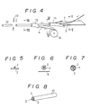
- rod-like material 10 which is illustrated in Fig. 8 and which is a raw material of the applicator 1 for makeup use of the present invention is obtained.
- the sheet-like material 4 is removed from the rod-like material 10 which is illustrated in Fig. 8 and which is a raw material of the applicator 1 for makeup use, and thus, rod-like bundle of fibers as illustrated in Fig. 1 (a) is prepared.
- a cutting device 20 is applied to the bundle of fibers at a position away from a predetermined distance from an end of the bundle.
- the cutting device illustrated in Fig. 2 has a straight part 21 and a circular part 22 on the knife edge as a nipper which is used to strip off covering of an electric wire does.
- the bundle of fibers are cut by engaging the knives 21 and 22 of the cutting device 20. Since the knife of the cutting device 20 is provided with the circular part 22, the fibers 2 of the core portion are not cut but only the crimped fibers 3 of the sheath portion are cut.
- thermoforming device 25 a part 1b of the fibers 3 of sheath portion corresponding to the base of of the applying portion 1a is thermoformed by a thermoforming device 25.
- the thermoforming device illustrated in Fig. 3 comprises two dies having tapered portions therein, and each die has a heater (not illustrated) mounted therein.
- the handle portion 1b corresponding to the base of the applying portion 1a is sandwiched by the dies, and the the crimped thermoplastic fibers 3 of the sheath portion located at the handle portion 1b are pressed by the dies when the dies are closed in a vertical direction and are thermally set in a pressed condition by the heat from the thermoforming device.
- thermoforming temperature is so selected that the thermoplastic fibers 3 of the sheath portion are softened, i.e., a temperature between 200°C and 230°C for acetate fibers and a temperature between 190°C and 240°C for acrylic fibers.
- thermoplastic fibers such as polyamide fibers
- the thermoforming temperature is set lower than the softening temperature of the fibers 2 of the core portion.
- the temperature of the portion in the thermoforming device 25, with which the fibers 2 of the core portion to be the applying portion 1a is contact when the bundle of the fibers are positioned on the thermoforming device 25, is so designed that it is lower than the thermoforming temperature.
- rod-like materials 10 the construction of which has been described with reference to Fig. 4, are fed to a hopper 30.
- the rod-like materials 10 are fed one by one to the cutting device 31 from the bottom of the hopper 30 while they are similarly directed.
- the cutting device 31 comprises: a pair of rotary wheels 32 for supporting the rod-like materials; a pressure roller 33 disposed between the wheels 32; two rotary knives 34 and 35 disposed coaxial with the pressure roller 33 on the extension of the axis of the pressure roller 33; and a guide plate 36 (see Figs. 13 to 17).
- the rod-like material supporting wheels 32 have number of recesses 32a for accommodating the rod-like materials 10 formed at the outer peripheries thereof as illustrated in Fig. 14.
- the pressure roller 33 serves to press the rod-like materials 10 against the guide plate 36, and the outer surface of the pressure roller 33 is so designed that its coefficient of friction is high.
- a material which has a high coefficient of friction is used at the outer surface of the pressure roller 33, or special treatment by which coefficient of friction becomes high, such as knurling, is done on the outer surface.
- the pressure roller 33 rotates in a direction denoted by an arrow integrally with the rod-like material supporting wheels 32.
- the guide plate 36 is a stationary disposed circular guide plate, and it prevents the rod-like materials 10 accommodated in the recesses 32a of the rod-like material supporting wheels 32 from being dropped, and at the same time, it cooperates with the pressure roller 33 so as to rotate the rod-like materials 10 on their axes.
- the rod-like materials 10 accommodated in the recesses 32a of the rod-like material supporting wheels 32 are moved along a circular path, i.e., a circular path formed between the guide plate 36 and the pressure roller 33, in accordance with the rotations of the rod-like material supporting wheels 32 and the pressure roller 33, the rod-like materials 10 are pressed to the guide plate 36 by the pressure roller 33, and as a result, the rod-like materials 10 move forwardly while they rotates in a direction opposite to the rotating direction of the pressure roller 33 (see Fig. 15).
- the rotary knife 34 located near the rod-like material supporting wheels 32 serves to form a circumferential cut, i.e., the second cut, to the sheet-like material 4 of the rod-like material 10
- the other rotary knife 35 serves to form a circumferential cut, i.e., the first cut, to the sheet-like material 4 of the rod-like material 10 and the fibers 3 of the sheath portion except for the fibers 2 of the core portion.
- the outer diameter of the rotary knife 35 is larger than that of the rotary knife 34.
- a guide 34a for preventing excessive cutting is disposed on the rotary knife 34 (see Fig. 16).
- the rotary knife 35 may be also provided with a guide for preventing excessive cutting.
- the rotary knives 34 and 35 may be rotated in synchronism with the rotations of the rod-like material supporting wheels 32 and the pressure roller 33, it is preferred that the rotary knives 34 and 35 are rotated at a speed higher than that of the rod-like material supporting wheels 32 and the pressure roller 33 in order to form cuts easily.
- the cutting device 31 Since the cutting device 31 has a construction as described above, the rod-like materials 10 fed from the hopper 30 to the cutting device 31 are accommodated in the recesses 32a of the rod-like material supporting wheels 32, and they are transferred along the circular path while they are rotated on their axes, and they are dispatched downwardly. During transfer along the circular path, cuts are formed in the sheet-like materials 4 and the fibers 3 of the sheath portions of the rod-like materials 10.
- the rod-like materials 10 dispatched one by one from the cutting device 31 are loaded on a rod-like material conveying device 40 which is disposed below the cutting device 31.
- the conveying device 40 is provided with a pair of chains with attachments and a number of receivers 42 of the rod-like materials 10.
- the attachment is indicated by reference numeral 41, the chain portion is omitted.
- the rod-like material receiver 42 is slidably supported on a shaft 43, which extends over the attachment 41, and is urged in one direction, i.e., to the left in Fig. 18, by a spring 44.
- a stationary guide cam 46 is fixed to a machine frame and extends preferably along the entire chains with attachments and at least along a portion from position B to position G in Fig. 11.
- the rod-like material receiver 42 has a guide roller 45 rotatably supported on the bottom thereof which is so urged by the spring 44 that the guide roller 45 contacts with the guide cam 46.
- the rod-like material receiver 42 has a gripping member 47 which is mounted swingably about a pivot axis 47a and which is normally urged by a spring 48 in such a direction that it grips the rod-like material 10.
- a guide roller 49 is disposed at an end of the gripping member 47. The guide roller 49 engages with a guide 50 disposed around position B in Fig. 11 and a guide 51 disposed before position G in Fig. 11, and it swings the gripping member 47 from the gripping position (see Figs. 19 to 22) to the releasing position (see Fig. 18 or 23) against the spring force of the spring 48.
- This embodiment is integrally provided with the device for removing the fibers 3 of the sheath portion and the sheet-like material 4 beyond the first cut formed by the cutting device 31 and the device for removing the sheet-like material 4 beyond the second cut formed by the cutting device 31.
- the removing device 60 comprises a conveyor 61, which moves at a speed almost same as the moving speed of the chains with attachment, and a plurality of sets of removing members 62, which are attached to the conveyor 61.
- each set of removing member 62 is provided with a pair of grasping members 63, ends of which are pivoted to each other by a pin, and a pair of link members 64, which control the opening and closing of the grasping members 63.
- the grasping members 63 are pivoted at an end of a hollow rod 65 and have at free ends thereof grasping surfaces 63a for holding the sheet-like material 4 and the fibers 3 of the sheath portion.
- the grasping surfaces 63a may be rugged in an appropriate shape in order to securely hold the sheet-like material 4 and the fibers 3 of the sheath portion.
- a rod 66 is slidably inserted into the hollow rod 65.
- An end of the rod 66 is pivoted to ends of the pair of link members 64, and the other ends of of the link members 64 are pivoted to central portions of the grasping members 63, respectively.
- the grasping members 63 become in a open condition illustrated in Fig. 18 and a closed condition illustrated in Fig. 19.
- the sliding movement of the rod 66 is performed by a suitable member, for example, by an appropriate cam fixed to the machine frame, by which the grasping members open and close in accordance with the movement of the conveyor 61.
- the removing device 60 cooperates with the rod-like material conveying device 40 which has been described previously so as to remove the fibers 3 of sheath portion and the sheet-like material 4 located at the end of the rod-like material 10. Mores specifically, first, as illustrated in Fig. 18, at position B below the cutting device 31, a rod-like material 10 dispatched from the cutting device 31 rides on a receiver 42 of the rod-like material conveying device 40. In this case, the gripping member 47 of the rod-like material conveying device 40 is located in a releasing position where the gripping member 47 is lifted by the guide 50, and the grasping members 63 of the removing device 60 are also open.
- the grasping members 63 When the receiver 42 and the grasping members 63 reach position C after they move to the right in Figs. 11 and 12 from the position B, the grasping members 63 are closed as illustrated in Fig. 19 so at to securely hold the end of the rod-like material 10 where the cuts are formed. At the position C, the engagement between the guide roller 49 and the guide 50 are disengaged, and the gripping member 47 similarly holds the other end of the rod-like material 10. In this case, the receiver 42 is moved to the left in Fig. 19 by means of the spring 44 and locates the advanced position where the receiver nears the grasping members 63.
- the receiver 42 and the grasping members 63 reach position D after they move to the right in Figs. 11 and 12 from the position C, the conditions illustrated in Fig. 20 appear. More specifically, the receiver 42 is moved to the right from the advanced position illustrated in Fig. 19 to a receded position illustrated in Fig. 20 where the receiver is away from the grasping members 63. During this movement, the gripping member 47 keeps to hold the end of the rod-like material 10, and the grasping members 63 also continue to close. Accordingly, the fibers 3 of sheath portion and the sheet-like material 4 located beyond the cut at the end of the rod-like material 10 are kept to be securely held, while the rod-like material 10 itself is moved to the receded position together with the receiver 42.
- the fibers 3 of sheath portion and the sheet-like material 4 beyond the cut are separated from the rod-like material 10.
- the fibers 2 of the core portion expose and the fibers 3 of the sheath portion expose sue to removal of the sheet-like material 4.
- the rod-like material 10, wherein the fibers 2 of the core portion and the fibers 3 of the sheath portion are exposed, is conveyed to a thermoforming device 70 while it is held by the gripping member 47.
- the thermoforming device 70 comprises a rotary disc 71, which has a plurality of holes 72 equidistantly formed on the disc surface thereof, and a heater 73, which is disposed integrally with the rotary disc 71 and which heats the rotary disc 71.
- the distance between the holes 72 formed on the rotary disc 71 is so designed that it is equal to that between the gripping members 47 of the rod-like material conveying device 40, and the rotary disc 71 is rotated at a speed equal to the moving speed of the rod-like material conveying device 40.
- the holes 72 serve to thermoform the exposed fibers 3 of the sheath portion in a desired shape, and the shape of the holes 72 is not limited as long as it can thermoform the exposed fibers 3 of the sheath portion.
- the hole 72 comprises a tapered portion and a cylindrical portion, which is connected to the tapered portion and into which the fibers 2 of the core portion are inserted when the fibers 3 of the sheath portion are thermoformed.
- thermoforming device 70 cooperates with the rod-like material conveying device 40 and thermoforms the fibers 3 of the sheath portion located at the rod-like material 10 in a manner set forth below.
- the receiver 42 is again moved to the left as denoted by an arrow in Fig. 22 toward the advanced position by means of the cooperation of the spring 44 and the guide 46, which guide is deflected toward the thermoforming device 70.
- the front end, i.e., the end where the fibers 2 of the core portion are exposed, of the rod-like material 10 is inserted into the hole 72 of the rotary heating disc 71 at position F illustrated in Fig. 11, and the fibers 3 of the sheath portion are thermoformed.
- the gripping member 47 is further advanced while the front end of the rod-like material 10 is inserted into the hole 72, and when the gripping member 47 is advance to a position opposite to position E in Fig. 11, i.e., the positions are symmetric with respect to the rotational axis, the receiver 42 is again guided by the guide 46 and is moved to the receded position so that the front end of the rod-like material 10 is taken out from the hole 72 of the rotary heating disc 71 (see the lower rod-like material 10 in Fig. 21).
- the fibers 3 of the sheath portion located at the front end of the rod-like material 10 is thermoformed in a conical shape, and the applicator 1 for makeup use of the present invention is obtained.
- the applicator 1 for makeup use drops and may be contained in a container disposed below the gripping member 47 or may be transferred to a predetermined station by means of a suitable conveyor 80.
- Fig. 26 is an elevation of another embodiment of a cutting device for forming slits to a rod-like material according to the present invention and a mechanism for transferring the rod-like material
- Fig. 27 is a plan view of the cutting device for forming slits to a rod-like material illustrated in Fig. 26.
- the rod-like materials 10 are fed to the transferring mechanism 130 one by one from the exit formed at the bottom of the hopper 30 while they are lined up.
- the transferring mechanism 130 of the illustrated embodiment is provided with four arms 131 radially extending and is intermittently turned by 90°.
- Each arm 131 has a pair of rollers 132 rotatably mounted at the end thereof.
- the number of the arms 131 and the intermittently turning angle are not limited to those described above and may be appropriately selected.
- the rod-like material 30 fed from the exit formed at the bottom of the hopper 30 enters between a pair of rollers 132 and is slightly held by the rollers 132.
- a cutting device 120 is disposed at a position which faces the end of the arm 131 when it turns by 90°.
- the cutting device 120 is provided with a cutter holder 124, two knives 121 and 123 held by the cutter holder 123, and a drive roller 124.
- the cutter holder 123 is connected to a suitable drive mechanism, such as a fluid pressure cylinder (not shown), and is vertically reciprocated in Fig. 26.
- the dive roller 124 is driven by a suitable mechanism, such as an electric motor, and contacts with the rod-like material 10 so as to turn it on its own axis.
- the rod-like material 10 is turned by the drive roller 124, and slits are formed on the periphery of the rod-like material 10.
- One 121 of the knives is used to form a circumferential slit, i.e., the first slit, to the sheet-like material 4 and crimped fibers 3 at the sheath portion of the rod-like material 10 and except for the fibers 2 at the core portion.
- the other 122 of the knives is used to form a circumferential slit, i.e., the second slit, to the sheet-like material 4 of the rod-like material 10.
- the arm 131 After the slits are formed, when the arm further turns by 90°, the arm 131 arrives a postion where it is almost vertical, and the rod-like material 10 slightly held by the pair of rollers 132 disposed at the end of the arm 131 drops into a hopper 133 disposed beneath the arm 131 by its own gravity.
- Fig. 28 is a plan view of a still another embodiment of a mechanism for transferring and thermoforming a rod-like-material.
- the rod-like material transferring device 140 is provided with a rod-like material receiving member 141 for receiving a plurality of rod-like materials 10.
- the rod-like material receiving member 141 has a plurality of recesses 142 for receiving the rod-like materials 10 formed thereon.
- the recess 142 has apertures 143 formed at the bottom thereof, which apertures are communicated with a flexible pipe 144, which is in turn connected to a vacuum source. Accordingly, while the vacuum source is operated, the rod-like member transferring device 140 is manually or mechanically neared to a position where a number of rod-like materials 10 are disposed, for example, a hopper, the rod-like materials 10 are sucked and are aligned to the recesses 142 formed on the receiving member 141. Under this condition, the receiving member 141 is manually or mechanically moved to the thermoforming device 160 by extending the flexible pipe 144.
- Another rod-like material transferring device 150 is so disposed that it faces the thermoforming device 160.
- the construction of the rod-like material transferring device 150 is similar to that of the foregoing rod-like material transferring device 140 and a rod-like material receiving member 151 has a plurality of recesses 152 for receiving the rod-like materials 10 formed thereon at a distance which is the same as that between the recesses 142 of the rod-like material transferring device 140.
- the recess 152 has apertures 153 formed at the bottom thereof, which apertures are communicated with a vacuum source via a flexible pipe 154.
- the vacuum source of the transferring device 150 While the vacuum source of the transferring device 150 is operated, the rod-like materials 10 sucked to the above-described rod-like material transferring device 140 is neared to the rod-like member transferring device 150. Then, while the rod-like materials 10 are exposed to the suction by the rod-like material transferring device 150, the rod-like material transferring device 140 is slightly moved so that air enters through the apertures 143 formed at the recesses 142. As a result, the rod-like materials 10 are easily transferred to the rod like-material transferring device 150.
- the thermoforming device 160 comprises a heater plate 161 and a drive mechanism, such as a hydraulic mechanism (not shown), for reciprocating the heater plate 161, and it can simultaneously thermoform a plurality of rod-like materials 10. More specifically, a plurality of holes 162 are formed corresponding to the recesses 152 of the rod-like material transferring device 150.
- the hole 162 comprises, for example, a tapered portion and a cylindrical portion connected to the tapered portion, into which cylindrical portion the fibers 2 of the core portion are inserted when the fibers 3 of the sheath portion are thermoformed.
- thermoforming device 160 nears the rod-like materials 10 sucked in the recesses 152 of the rod-like material transferring device 160 and thermoforms the fibers 3 of the sheath portion at the ends of the rod-like materials 10 while it accommodates the ends of the rod-like materials 10 within the holes 162.
- a press device 170 is disposed in parallel with the thermoforming device 160 and that the rod-like materials 10 which have been thermoformed are subjected to a pressing operation.
- the rod-like materials 10 are transferred to the pressing station by laterally moving the rod-like material transferring device 150 just after they are heated in the thermoforming device 160. If this method is applied, since heat remains in the rod-like materials 10, it may be unnecessary to heat the die in the press device 170.
- the press device 170 can simultaneously a plurality of rod-like materials 10 sucked in the recesses 152 of the rod-like material transferring device 150.
- the cost of raw material of the applicator for makeup use is very inexpensive, since the applicator comprises a bundle of fibers, and since the number of the fibers may be small because the crimped fibers are used as the fibers of sheath portion.
- the fibers of the sheath portion which comprises crimped fibers and which surround straight fibers of the core portion, are thermoformed at the base of the applying portion while they are not ground or abraded and while their amount is maintained. Accordingly, the thermoformed fibers of the sheath portion can securely hold the fibers of the applying portion, i.e., the fibers of the core portion. Since the applying portion is securely held and since accordingly the base of the applying portion is not bent easily, lines can be drawn at will by makeup cosmetics and the desired amount of makeup cosmetics can be applied to the objective portion.
- the applicator for makeup use of the present invention can be a suitable shape for a lip brush since the straight fibers of the applying portion can be arranged flat by thermoforming the base of the applying portion of the applicator of the present invention in a flat shape.
- the applicator can be used for trial use of cosmetic when the cosmetic has been previously attached to the fibers of sheath portion of the applying portion, and the applicator is very convenient to use.
- the fibers of the sheath portion are removed at an end of the rod-like bundle of fibers of a predetermined length while the fibers of the core portion are remained so that the fibers of the core portion are exposed, and the fibers of the sheath portion around the base portion of the exposed fibers of the core portion are thermoformed. Since abrading or grinding operation is unnecessary in the method of the present invention, manufacture of the applicator for makeup use of the present invention does not take time, and time required for manufacturing a single applicator is short. Accordingly, according to the method and apparatus of the present invention, the applicators can be manufactured at high productivity.
Abstract
Description
- The present invention relates to an applicator for makeup use, a method for producing the same, and an apparatus for effecting the same.
- More specifically, the present invention relates to an applicator for makeup use, which is suitable for applying a cosmetic to a customer when a instructor teaches how to apply the cosmetic to the customer's face at a cosmetic store, which has a high applying capability and which is inexpensive since it is of a disposal type.
- The present invention also relates to a method for producing such a suitable applicator, and an apparatus for effecting the method.
- Makeup cosmetics include various kind of cosmetics, such as lipstick, rouge, eye shadow. As an applicator of such cosmetics, brush made of horse bristles or goat bristles and an applicator made of foam, such as rubber foam or polyurethane have been used.
- In the meantime, there is a tendency to actually try to apply makeup cosmetic at a cosmetic store when makeup cosmetics are sold. In this case, an applicator for makeup cosmetic is used.
- In view of the objective portion for makeup, i.e., eyes, lips and so on, it is undesirable from sanitary point of view to use the single same applicator for an unspecified number of persons on trial application of makeup cosmetic.
- Accordingly, when the objective persons, to whom cosmetics are trially applied, are different, the applicator is wiped by tissue paper or is cleaned and dried after application to one person. Therefore, it is troublesome.
- A conventional applicator formed in a stick or a brush includes an applying portion made of straight fibers or bristles. The base portion of the fibers or bristles, which serve as the applying portion, is tightly fastened by a metal band. Then, the applying portion is attached to a handle made of a synthetic regin or a metal. As described above, manufacture of such a conventional applicator is troublesome, and accordingly, the applicator is expensive. Consequently, the conventional applicator can not be disposed of once it is used. Especially, an applicator is expensive when it has an applying portion made of horse bristle or goat bristle, and therefore, it is uneconomic to dispose of such an expensive applicator on every use.
- When foam is used as an applying portion of an applicator, the applicator is manufactured by connecting the applying portion to a handle by an adhesive, after the surface of core member made of thin synthetic regin sheet is covered by an foam to form the applying portion. In another applicator wherein foam is used as an applying portion, the applicator is manufactured by covering a core portion made of a synthetic regin by foam, after a thin portion, which will be the core portion, and a thick portion, which will be a handle, are molded in one body.
- In both the manufacturing methods described above, it is necessary to cover the core portion by foam formed in a predetermined shape in each applicator. Accordingly, operations are required wherein individual member of synthetic regin, which will be a core portion, is set at a predetermined position, thereafter it is covered by foam, and the foam surrounding the core portion is punched. Thus, the operation is very troublesome, and the manufacturing cost is expensive. Accordingly, the thus manufactured applicator is uneconomic as an applicator of a disposal type.
- In order to obviate the above-described problems, the present inventor proposed in Japanese Patent Application Laid-open No. Hei 1-119203 and Japanese Utility Model Application Laid-open No. Hei 1-72813 an applicator for makeup use made of bundle of acetate fibers, wherein only an applying portion comprises straight fibers and the remaining portions comprise crimped fibers. Further, the inventor proposed a method for manufacturing the applicator which comprises: a first step wherein after crimped acetate fibers are gathered and formed in a rod, the rod is cut in a predetermined length; a second step wherein an end of the rod formed in the first step is sharpened by grinding to form an applying portion; a third step wherein only the applying portion is applied with or impregnated with treating liquid including water so that the crimped fibers are straightened in straight fibers; and a fourth step wherein the applying portion obtained in the third step is dried.
- According to the applicator for cosmetic use and the method for manufacturing the same, which the present inventor previously proposed, the applying portion is sharpened by abrading and grinding one end of the bundle of fibers. However, the operational efficiency for abrading or grinding operation of the bundle of crimped fibers in a pointed end is low, and accordingly, the productivity is low. Further, the portion which is abraded or ground may be easily fluffed, and accordingly, the quality of the obtained applicator may be deteriorated.
- In addition, since the portion near the base of the applying portion is abraded or ground, the support of the applying portion becomes weak, and the applicator is not stiff. As a result, when a makeup cosmetic, such as lipstick, is applied with the proposed applicator, the applicator may bend at the base of the applying portion, and accordingly, the cosmetic cannot be applied well to the objective portion, i.e., the lip. More specifically, it is difficult for a user of the applicator to draw a line at will or to apply the cosmetic to the objective portion.
- Furthermore, since a lip brush is used both to draw the outlines of the lip and to apply lipstick to entire surface of the lip, it is preferred for the front end of the lip brush to be flat. However, it is difficult to obtain an applicator with flat end in accordance with the previous proposal.
- Besides, according to the previous proposal, the portion in the bundle of the fibers, which will be the applying portion, is treated with treating liquid so that the crimped fibers are straightened to obtain straight fibers, however, the crimps often remain in the fibers. If the crimps remain, makeup cosmetics may enter into the applying portion of the applicator, i.e., clearances formed by the crimps between the fibers, and the cosmetics will not come out easily. Accordingly, the cosmetics cannot be applied well to the objective skin.
- The present invention has been achieved taking into consideration the above-described background, and an object of the present invention is to provide an applicator for makeup which is inexpensive and easy to use, and by which makeup cosmetics can be suitably applied at will.
- Another object of the present invention is to provide a method which can manufacture the above-described applicator for makeup use of the present invention provided with a sufficient applying capability at low cost and at high productivity.
- A still other object of the present invention is to provide an apparatus which is suitable for performing the above-described method of the present invention.
-
- According to the present invention, the above-described object is achieved by an applicator for makeup use, wherein an applying portion and at least a front portion, i.e., an end close to the applying portion, of a handle portion are made of a bundle of fibers, characterized in that:
the bundle of fibers comprises a sheath portion and a core portion, the core portion being made of a bundle of fibers comprising a plurality of straight fibers, and the sheath portion being made of thermoplastic fibers, which have crimps therein and partially adhere to each other, and wrapping about the core portion;
the applying portion of the applicator is made of the straight fibers of the core portion;
the handle portion is made of the fibers of the core portion and the fibers of the sheath portion; and
the fibers of the sheath portion are thermoformed at the handle portion located near a base portion of the applying portion. - Further, according to the present invention, the above-described object is achieved by a method for producing an applicator for makeup use comprising:
a step for preparing a rod-like bundle of fibers of a predetermined length which comprises a core portion made of a plurality of straight fibers and a sheath portion made of thermoplastic fibers, which have crimps therein and partially adhere to each other, and wrapping about the core portion;
a step for removing the fibers of the sheath portion at an end of the bundle while the fibers of the core portion are remained so that the fibers of the core portion are exposed; and
a step for thermoforming the thermoplastic fibers of the sheath portion around a base portion of the exposed fibers of the core portion. - Furthermore, according to the present invention, the above-described object is achieved by an apparatus for producing an applicator for makeup use, which comprises:
a means for feeding a rod-like bundle of fibers of a predetermined length which comprises a core portion made of a plurality of straight fibers and a sheath portion made of thermoplastic fibers, which have crimps therein and partially adhere to each other;
a cutting means for forming circumferential cut to the fibers of the sheath portion at an end of the bundle of fibers at a depth sufficient to reach the fibers of the core portion;
a means for removing the fibers of the sheath portion located at the end beyond the cut; and
a means for thermoforming the thermoplastic fibers of the sheath portion around the cut. - The cost of raw material of the applicator for makeup use of the present invention is very inexpensive, since the applicator comprises a bundle of fibers, and crimped fibers are used as the fibers of sheath portion.
- Further, there is no problem inherent to the previously proposed applicator that the makeup cosmetics enter into clearances between the crimped fibers since the originally straight fibers are used for the applying portion.
- In the applicator for makeup use of the present invention, the fibers of the sheath portion, which comprises crimped fibers and which surrounds straight fibers of the core portion, are thermoformed at the base of the applying portion while they are not ground or abraded and while their amount is maintained. Accordingly, the thermoformed fibers of the sheath portion can securely hold the fibers of the applying portion, i.e., the fibers of the core portion. As described above, since the applying portion is securely held and since accordingly the base of the applying portion is not bent easily, lines can be drawn at will by makeup cosmetics and the desired amount of makeup cosmetics can be applied to the objective portion.
- In addition, the applicator for makeup use of the present invention can be a suitable shape for a lip brush since the straight fibers of the applying portion can be arranged flat by thermoforming the base of the applying portion of the applicator of the present invention in a flat shape.
- Besides, the applicator for makeup use of the present invention is not fluffed different from that obtained by abrading or grinding since the base of the applying portion is thermoformed.
- According to the manufacturing method of the present invention, the fibers of the sheath portion are removed at an end of the rod-like bundle of fibers of a predetermined length while the fibers of the core portion are remained so that the fibers of the core portion are exposed, and the fibers of the sheath portion around the base portion of the exposed fibers of the core portion are thermoformed. Since abrading or grinding operation is unnecessary in the method of the present invention, manufacture of the applicator for makeup use of the present invention does not take time, and time required for single applicator is short. Accordingly, according to the method of the present invention, the applicators can be manufactured at high productivity.
- The apparatus for producing an applicator for makeup use of the present invention comprises:
a means for feeding a rod-like bundle of fibers of a predetermined length which comprises a core portion made of a plurality of straight fibers and a sheath portion made of thermoplastic fibers, which have crimps therein and partially adhere to each other;
a cutting means for forming circumferential cut to the fibers of the sheath portion at an end of the bundle of fibers at a depth sufficient to reach the fibers of the core portion;
a means for removing the fibers of the sheath portion located at the end beyond the cut; and
a means for thermoforming the thermoplastic fibers of the sheath portion around the cut, and the applicators for makeup use of the present invention can be manufactured one after another. - The present invention will now be explained in detail with reference to the accompanying drawings which show some embodiments of the present invention, wherein:
- Figs. 1 (a) to 1 (d) are front views showing process for manufacturing applicator for makeup use of the present invention;
- Fig. 1 (e) is a front view of the obtained applicator for makeup use of the present invention;
- Fig. 1 (f) is a plan view of Fig. 1 (e);
- Fig. 1 (g) is a side view seen along the arrow in Fig. 1 (e);
- Figs. 2 (a) and 2(b) are side views showing operational conditions of an embodiment of a cutting device of a manufacturing apparatus of the present invention wherein:
- Fig. 2 (a) corresponds to Fig. 1 (a); and
- Fig. 2 (b) is a cross sectional view along line IIb-IIb in Fig. 1 (b);
- Fig. 3 is a cross sectional view showing an embodiment of a thermoforming device of the manufacturing apparatus of the present invention;
- Fig. 4 is a perspective view explaining a step for manufacturing rod-like material which is a raw material of the applicator for makeup use of the present invention;
- Fig. 5 is a cross sectional view taken along line V-V in Fig. 4;
- Fig. 6 is a cross sectional view taken along line VI-VI in Fig. 4;
- Fig. 7 is a cross sectional view taken along line VII-VII in Fig. 4;
- Fig. 8 is a perspective view manufactured by the manufacturing step illustrated in Fig. 4;
- Figs. 9 (a) to 9 (d) show another embodiment of the applicator of the present invention, wherein:
- Fig. 9 (a) is a front view of a
handle portion 1b before it is thermoformed; - Fig. 9 (b) is a front view of a
handle portion 1b after it is thermoformed; - Fig. 9 (c) is a plan view of Fig. 9 (b); and
- Fig. 9 (d) is a right side view of Fig. 9 (b);
- Fig. 9 (a) is a front view of a
- Fig. 10 is a perspective view of another embodiment of the applicator for makeup use of the present invention.
- Fig. 11 is a schematic front view of a manufacturing apparatus for effecting the manufacturing method of the present invention;
- Fig. 12 is a schematic plan view of Fig. 11;
- Fig. 13 is a side view of a cutting device for forming cut to a rod-like material;
- Fig. 14 is an end elevation along line A-A in Fig. 13;
- Fig. 15 is an end elevation along line B-B in Fig. 13;
- Fig. 16 is an end elevation along line C-C in Fig. 13;
- Fig. 17 is an end elevation along line D-D in Fig. 13;
- Figs. 18 to 20 are side views seen in arrow A in Fig. 11 and showing the operational conditions of a device for removing fibers of the sheath portion and the sheet-like material at an end beyond a cut, wherein:
- Fig. 18 is a side view at position B in Fig. 11;
- Fig. 19 is a side view at position C in Fig. 11; and
- Fig. 20 is a side view at position D in Fig. 11;
- Figs. 21 and 22 are views showing the operational conditions of a device for thermoforming fibers of the sheath portion around the cut and a device for transferring a rod-like material, wherein:
- Fig. 21 is an end elevation seen along arrow A in Fig. 11 at position E in Fig. 11; and
- Fig. 22 is an end elevation at position F in Fig. 11;
- Fig. 23 is an end elevation showing the operational conditions of the device for transferring a rod-like material seen along arrow A in Fig. 11 at position G in Fig. 11;
- Fig. 24 is a partially cross sectioned front view of still another embodiment of an applicator for makeup use according to the present invention;
- Fig. 25 is a perspective view of a further embodiment of an applicator for makeup use according to the present invention;
- Fig. 26 is an elevation of another embodiment of a cutting device for forming slits to a rod-like material according to the present invention and a mechanism for transferring the rod-like material;
- Fig. 27 is a plan view of the cutting device for forming slits to a rod-like material illustrated in Fig. 26; and
- Fig. 28 is a plan view of a still another embodiment of a mechanism for transferring and thermoforming a rod-like-material.
- Referring to Figs. 1 to 3, wherein:
- Figs. 1 (a) to 1 (d) are front views showing process for manufacturing applicator for makeup use of the present invention;
- Fig. 1 (e) is a front view of the obtained applicator for makeup use of the present invention;
- Fig. 1 (f) is a plan view of Fig. 1(e);
- Fig. 1 (g) is a side view seen along the arrow in Fig. 1 (e);
- Figs. 2 (a) and 2 (b) are side views showing operational conditions of an embodiment of a cutting device of a manufacturing apparatus of the present invention wherein:
- Fig. 2 (a) corresponds to Fig. 1 (a); and
- Fig. 2 (b) is a cross sectional view along line IIb-IIb in Fig. 1 (b); and
- Fig. 3 is a cross sectional view showing an embodiment of a thermoforming device of the manufacturing apparatus of the present invention.
- An applicator 1 for makeup use of the embodiment illustrated in Fig. 1 comprises a bundle of fibers, which comprises a
core portion 2 and asheath portion 3 surrounding thecore portion 2. - The
core portion 2 comprises a plurality ofstraight fibers 2, and thesheath portion 3 comprises a plurality ofthermoplastic fibers 3 having crimps, and thefibers 3 of the sheath portion partially adhere to each other. - As illustrated in Figs. 1 (e) to 1 (g), the applying
portion 1a of the applicator 1 for makeup use comprises thestraight fibers 2 of the core portion, and a handle portion designated byreference numerals fibers - Since all the fibers of the applying
portion 1a are thestraight fibers 2 as described above, makeup cosmetics do not enter clearance formed between the crimped fibers. Further, since thehandle portion 1c comprisesstraight fibers 2 of the core portion and thefibers 3 of the sheath portion, which have crimps and partially adhere to each other, the handle portion has a suitable stiffness and elasticity and is easily held as the applicator 1 for makeup use. - According to the present invention, in the
handle portion 1b around the base of the applyingportion 1a, thefibers 3 of the sheath portion are thermoformed so that the clearance between the crimped fibers becomes small, and accordingly, the hardness of thehandle portion 1b is enhanced relative to that before thermoforming operation. In this case, in thehandle portion 1b, which is adjacent to the applyingportion 1a, it is preferred that the portion near the applyingportion 1a is thermoformed more than the portion away from the applyingportion 1a. - For example, in the embodiment illustrated in Figs. 1 (e) to 1 (g), the
handle portion 1b is pressed in a vertical direction and is tapered toward the applyingportion 1a when it is seen from the front, while it has a width which is almost the same as that before it is thermoformed. Thus, the front end of thehandle portion 1b, i.e., the end close to the applyingportion 1a, is flat, and thefibers 2 of the core portion are also formed in a flat condition. The applyingportion 1a of the applicator 1 for makeup use having a flat shape is suitable for a lip brush. - The shape of the
handle portion 1b around the base of the applyingportion 1a is not limited, and it may be a conical shape or may be uniformly pressed in a flat shape as it will be explained later with reference to Fig. 9. - The materials suitable for the
fibers 2 of the core portion of the applicator for makeup use of the present invention are rayon, nylon, acrylic or polyester. Since thefibers 3 of the sheath portion of thehandle portion 1b which is located around the base of the applyingportion 1a is thermoformed, the material which is not softened or melt at a thermoforming temperature of thehandle portion 1b is preferable for thefibers 2 of the core portion. Especially, rayon is suitable for thefibers 2 of the core portion. - The thickness of
individual fibers 2 of the core portion is preferably between 20 and 100 denier. For example, it is selected between 40 and 70 denier if the applicator is a lip brush. - The total denier of the
fibers 2 of core portion is appropriately selected depending on the usage of the applicator, such as a blush brush, a lip brush, or a brush for eye shadow. For example, the total denier is selected between 15,000 and 25,000 denier for a blush brush or a lip brush. - Thermoplastic fibers, especially acetate fibers or acrylic fibers are suitable, for the materials of the
fibers 3 of the sheath portion of the applicator for makeup use of the present invention. Alternatively, conjugate fibers which are composed of fibers having a relatively low melting point and fibers having a relatively high melting point, may be used for thefibers 3 of the sheath portion of the applicator for makeup use. The conjugate fibers are, for example, sheath and core fibers, the core of which is made of polyester, polypropylene or the like and the sheath of which is made of polyethylene of a low melting point or the like, Further, thefibers 3 of the sheath portion may be any thermoplastic fibers which are provided with a hot melt adhesive of a powder type applied thereto. The powder type hot melt adhesive can be sprinkled over thefibers 3 to be the sheath portion in the process for manufacturing the applicator for makeup use before thefibers 3 of the sheath portion surround thefibers 2 of the core portion. - Thickness of
individual fibers 3 of the sheath portion is preferably between 2 and 10 denier. The total denier of thefibers 3 of the sheath portion is preferably selected taking the total denier of thefibers 2 of the core portion into consideration so that thefibers 3 of the sheath portion surely surround thefibers 2 of the core portion. In this case, it is preferred that a layer, i.e., the sheath portion, more than 1 mm is formed around thefibers 2 of the core portion before they are thermoformed. - The conditions in crimps of the
fibers 3 of the sheath portion are not limited, however, the number of crimps is selected to be more than 1 per 1cm. It is preferred to usefibers 3 having uniform crimps between 2 and 12 per 1 cm. - The reason why crimped fibers are used for the sheath portion is that the amount of used fibers can be economized, and that accordingly, the price of the manufactured applicator can be reduced. For example, when crimped fibers, individual denier of which is 2 denier and which have crimps of between 3 and 10 per 1 cm, are used to obtain a bundle of fibers, the diameter of which bundle is 6.5 cm, the number of the required fibers is about 40,000. Contrary to this, if it is tried to obtain a bundle having the same diameter by using only straight fibers, the fibers of 130,000 are necessary.
- The crimped fibers of sheath portion are partially adhered to each other. This adhesion is done by partially applying solvent or plasticizer to the fibers so that the fibers are partially dissolved and are adhered to each other at points thereon. The partial adhesion of the fibers on their points preserves the shape of the gathered fiber bundle in a rod and adds a suitable hardness to the rod.
- The following agents can be used as the solvent or the plasticizer which partially adhere the fibers.
- In case of acetate fibers: butyrolactone; ethylene glycol monophenyl ether; triacetin; polyethylene glycol diacetate; dipropionate; dibutylate; dimethoxyethyl phthalate; triethyl citrate; 1,3-butylene glycol diacetate; and so on.
- In case of acrylic fibers: dimethylformamide; cyclohexane; dimethyl sulfoxide; and so on.
- The methods for applying the solvent or the plasticizer to the fibers may be conventionally known suitable methods, such as a method using a spray gun or a roller coating method, and the solvent or the plasticizer are applied to the fibers from the upper and lower sides thereof.
- If the amount of the solvent or the plasticizer is excessively large, cellulose acetate may be dissolved and becomes in a dope-like condition. Accordingly, it is preferred that the solvent or the plasticizer is uniformly applied to the fibers.
- Contrary to this, if the amount of the solvent or the plasticizer is too small, the adhered fibers may be torn easily, and accordingly, the usability of the obtained applicator is poor since the handle supporting portion may be split upon application of makeup cosmetics.
- In view of the background described above, it is suitable that the amount of the solvent or the plasticizer relative to that of the acetate fibers is between 2 and 20 % by weight.
- In the foregoing descriptions, the
crimped fibers 3 of sheath portion are partially adhered to each other by partially applying solvent or plasticizer to the fibers so that the fibers are partially dissolved and are adhered to each other, however, in another method, the partial adhesion can be done by heating. More specifically, in case of conjugate fibers, fibers with a low melting point are partially melted by heating so thatfibers 3 of the sheath portion are partially adhered to each other. Alternatively, when a hot melt adhesive of a powder type is sprinkled overthermoplastic fibers 3, the hot melt adhesive is melted by heating so that crimpedfibers 3 of the sheath portion are partially adhered to each other. The applicators for makeup use which are manufactured without using solvent or plasticizer as described above are suitable for applying cosmetic containing solvent, such as manicure. - Figs. 9 (a) to (d) show another embodiment of the applicator of the present invention, wherein:
- Fig. 9 (a) is a front view of a
handle portion 1b before it is thermoformed; - Fig. 9 (b) is a front view of a
handle portion 1b after it is thermoformed; - Fig. 9 (c) is a plan view of Fig. 9 (b); and
- Fig. 9 (d) is a right side view of Fig. 9 (b).
- The applicator for makeup use of this embodiment is the same as that of the first embodiment described above except for the following points.
- The applicator 1 for makeup use of this embodiment includes a sheet-
like material 4 made of paper or synthetic resin film wrapping around the outer periphery of thehandle portion 1c. Further, thehandle portion 1b located near the base of the applyingportion 1a is uniformly pressed and almost theentire handle portion 1b is flat. - As it will be described later, the sheet-
like material 4 is used to form a rod-like bundle of fibers comprising sheath and core portions. - Although in the first embodiment, the sheet-
like material 4 is removed, it is preferred that the sheet-like material 4 is remained in the applicator for makeup use as a part of the handle portion so as to wrap the outer periphery of the rod-like bundle of fibers. More specifically, wrapping of the rod-like bundle of fibers by the sheet-like material 4 enhance the hardness of thehandle portion 1c of the applicator 1 for makeup use, and accordingly, bending or torsion of the handle portion upon application of makeup cosmetics can be prevented. Therefore, the usability of the applicator 1 for makeup use is increased. Further, when the sheet-like material 4 is colored, the applicator 1 for makeup use obtains an impression of high-grade articles. In addition, although nakedcrimped fibers 3 of sheath portion may easily adsorb dirt, the sheet-like material 4 does not adsorb dirt relative to thefibers 3 of sheath portion. - In the embodiment illustrated in Figs. 9 (a) to 9 (d), the sheet-
like material 4 covers a part of thehandle portion 1c. When a thermally shrinkable film is used as the sheet-like material 4, thehandle portion 1b near the base of the applyingportion 1a may also be covered by the film, and the film may be thermally shrunk together with thefibers 3 of sheath portion when thefibers 3 are thermoformed. - Fig. 10 is a perspective view of another embodiment of the applicator for makeup use of the present invention. This embodiment is different from the applicator for makeup use of the first embodiment in that the length of the handle portion of the applicator for makeup use of the present invention, i.e., the
handle portions fibers cylinder member 5 made of a paper cylinder or a synthetic resin pipe and prepared in addition to the handle portion. In this embodiment, the applicator for makeup use of the present invention is disposed of after use and thecylinder member 5 can be used repeatedly. Accordingly, this embodiment is economic. In addition, the applicator for makeup use of this embodiment obtains an impression of high-grade articles due to thecylinder member 5. - Fig. 24 is a partially cross sectioned front view of still another embodiment of an applicator for makeup use according to the present invention. In this embodiment, unlike the foregoing embodiments, the fibers 2' of said core portion which constitute the applying portion have cosmetic, such as rouge or eye shadow, attached thereto. In order to protect the applying portion which has cosmetic attached thereto, a
cap 6 is covered over the applying portion. When the applicator is used, thecap 6 is removed from the front portion of the applicator, and it may be covered at the handle portion of the applicator opposite to the applying portion. Thus, thecap 6 becomes a part of the handle portion and facilitate easy use of the applicator. Further, thecap 6 performs a role similar to that of thecylinder member 5 illustrated in Fig. 10. - Fig. 25 is a perspective view of a further embodiment of an applicator for makeup use according to the present invention. In this embodiment, similar to that illustrated in Fig. 24, cosmetic is adhered to the fibers 2' of the core portion which serve as the applying portion. In place of the
cap 6 illustrated in Fig. 24, a thin transparent film, made of plastic resin, such as polyvinyl chloride, polypropylene, or polyethylene, and folded in two, is used to protect both the sides of the applying portion as illustrated in Fig. 25. Since theprotection sheet 7 sticks to the cosmetic attached to the applying portion, it is not removed easily. - In order to attach cosmetic to the fibers of the core portion forming the applying portion, after the applicator for makeup use such as described above with reference to the foregoing embodiments has been produced, the ends of the fibers at the core portion may be rubbed with cosmetic so as to attach the cosmetic thereto or the ends of the fibers at the core portion may be dipped in cosmetic which is in solution or in a liquid condition.
- The embodiments of the applicator for makeup use illustrated in Figs. 24 and 25 are suitable for providing a customer or consumer with cosmetic for trial use. More specifically, since the applicator for makeup use itself is provided with cosmetic for trial use, it is easy for the customer or consumer to try to apply cosmetic. Further, conventionally, cosmetic for trial use has been usually contained in a small container and is distributed to a consumer, the quantity of the distributed cosmetic usually exceeds that needed for one time trial because of the volume of the container. Contrary to the conventional method, according to the embodiments, cosmetic, the quantity of which is only for one trial application, is attached to the disposal applicator, waste of cosmetic is minimized compared with the conventional method.
- When cosmetic for trial use is intended to be attached to the applicator, it is preferred that the
cap 6 is made of a transparent material, such as plastics, since the color of the attached cosmetic can be observed from the outside. In addition, it is preferred that the color of the fibers at the core portion is transparent or white, since the color of the cosmetic can be easily recognized. - When rouge is attached to the applicator, it is preferred that the handle portion is so thermoformed that the applying portion becomes flat. When, eye shadow is attached to the applicator, it is preferred that the handle portion near the applying portion is so thermoformed that the applying portion becomes conical. It is preferred that the handle portion is covered by the sheet-like material as illustrated in Figs. 24 and 25, however, the sheet-like material may be omitted.
- Previous to the explanation of a method and an apparatus for producing an applicator for makeup use of the present invention, an explanation will now be done with regard to a method for producing a rod-
like material 10, which is a raw material of the applicator for makeup use of the present invention, referring to Figs. 4 to 8. - Fig. 4 is a perspective view explaining a step for manufacturing rod-like material which is a raw material of the applicator for makeup use of the present invention;
- Fig. 5 is a cross sectional view taken along line V-V in Fig. 4;
- Fig. 6 is a cross sectional view taken along line VI-VI in Fig. 4;
- Fig. 7 is a cross sectional view taken along line VII-VII in Fig. 4; and
- Fig. 8 is a perspective view manufactured by the manufacturing step illustrated in Fig. 4.
- As it is illustrated in Figs. 4 and 5, a tow-like bundle of crimped
thermoplastic fibers 3 is opened by a tow treating apparatus of a conventionally known type. A plurality ofstraight filaments 2 are gathered together and are fed to the opened tow like bundle of crimpedthermoplastic fibers 3. - Before or after the
straight filaments 2 are fed, solvent or plasticizer which has been explained with the first embodiment is applied to both the upper and lower sides of the opened tow-like bundle ofthermoplastic fibers 3 by means of a spray gun or a coating roller. - Thereafter, the tow-like bundle of
thermoplastic fibers 3 in a opened condition and thestraight filaments 2 are guided by means of aguide 11 so that the bundle ofthermoplastic fibers 3 wraps around thestraight filaments 2 and that the bundle ofthermoplastic fibers 3 are gathered. - A sheet-
like material 4 is withdrawn from aroll 14, on which the sheet-like material such as paper or film is wound, and is fed to the gathered bundle of thermoplastic fibers 3 (see Fig. 6). - Then, the
guide 12 guides the sheet-like material 4 so that the sheet-like material 4 covers the outer periphery of the bundle ofthermoplastic fibers 3. In this case, adhesive may be applied to a longitudinal edge of the sheet-like material 4, and the longitudinal edges of the sheet-like material 4 may be overlapped with each other and may be adhered to each other (see Fig. 7). - A continuous rod-like material which has passed through the
guide 12 is cut in a predetermined length by a cuttingdevice 13. When the cut rod-like material is allowed to cool or is cooled, partial adhesion of the fibers is formed on points of the bundle of crimpedthermoplastic fibers 3 and the shape of the bundle of crimpedthermoplastic fibers 3 is fixed. As described above, rod-like material 10 which is illustrated in Fig. 8 and which is a raw material of the applicator 1 for makeup use of the present invention is obtained. - A method and apparatus for manufacturing the applicator for makeup use of the present invention will now be explained with reference to an embodiment illustrated in Figs. 1 to 3.
- The sheet-
like material 4 is removed from the rod-like material 10 which is illustrated in Fig. 8 and which is a raw material of the applicator 1 for makeup use, and thus, rod-like bundle of fibers as illustrated in Fig. 1 (a) is prepared. A cuttingdevice 20 is applied to the bundle of fibers at a position away from a predetermined distance from an end of the bundle. - The cutting device illustrated in Fig. 2 has a
straight part 21 and acircular part 22 on the knife edge as a nipper which is used to strip off covering of an electric wire does. - As illustrated in Figs. 1 (b) and 2 (b), the bundle of fibers are cut by engaging the
knives device 20. Since the knife of the cuttingdevice 20 is provided with thecircular part 22, thefibers 2 of the core portion are not cut but only the crimpedfibers 3 of the sheath portion are cut. - When the cutting
device 20 is moved to the right as indicated by arrow A in Fig. 1 (b), thefibers 3 of sheath portion at the cut end is moved with the cuttingdevice 20 and is removed, and then thefibers 2 of the core portion which will be the applyingportion 1a exposes as illustrated in Fig. 1 (c). - Then, as illustrated in Figs. 1 (d) and 3, a
part 1b of thefibers 3 of sheath portion corresponding to the base of of the applyingportion 1a is thermoformed by athermoforming device 25. The thermoforming device illustrated in Fig. 3 comprises two dies having tapered portions therein, and each die has a heater (not illustrated) mounted therein. Thehandle portion 1b corresponding to the base of the applyingportion 1a is sandwiched by the dies, and the the crimpedthermoplastic fibers 3 of the sheath portion located at thehandle portion 1b are pressed by the dies when the dies are closed in a vertical direction and are thermally set in a pressed condition by the heat from the thermoforming device. - The thermoforming temperature is so selected that the
thermoplastic fibers 3 of the sheath portion are softened, i.e., a temperature between 200°C and 230°C for acetate fibers and a temperature between 190°C and 240°C for acrylic fibers. When thermoplastic fibers such as polyamide fibers are used as thefibers 2 of the core portion, it is preferred that the thermoforming temperature is set lower than the softening temperature of thefibers 2 of the core portion. Alternatively, it is preferred that the temperature of the portion in thethermoforming device 25, with which thefibers 2 of the core portion to be the applyingportion 1a is contact when the bundle of the fibers are positioned on thethermoforming device 25, is so designed that it is lower than the thermoforming temperature. - When the bundle of the fibers is taken up from the
thermoforming device 25, the applicator 1 for makeup use of the present invention which is illustrated in Figs. 1 (e) to 1 (g) is obtained. - Another embodiment of a method and an apparatus for manufacturing the applicator for makeup use of the present invention will now be explained with reference to an embodiment illustrated in Figs. 11 to 26.
- Fig. 11 is a schematic front view of a manufacturing apparatus for effecting the manufacturing method of the present invention;
- Fig. 12 is a schematic plan view of Fig. 11;
- Fig. 13 is a side view of a cutting device for forming cut to a rod-like material;
- Fig. 14 is an end elevation along line A-A in Fig. 13;
- Fig. 15 is an end elevation along line B-B in Fig. 13;
- Fig. 16 is an end elevation along line C-C in Fig. 13;
- Fig. 17 is an end elevation along line D-D in Fig. 13;
- Figs. 18 to 20 are side views seen in arrow A in Fig. 11 and showing the operational conditions of a device for removing fibers of the sheath portion and the sheet-like material at an end beyond a cut, wherein:
- Fig. 18 is a side view at position B in Fig. 11;
- Fig. 19 is a side view at position C in Fig. 11; and
- Fig. 20 is a side view at position D in Fig. 11;
- Figs. 21 and 22 are views showing the operational conditions of a device for thermoforming fibers of the sheath portion around the cut and a device for transferring a rod-like material, wherein:
- Fig. 21 is an end elevation seen along arrow A in Fig. 11 at position E in Fig. 11; and
- Fig. 22 is an end elevation at position F in Fig. 11; and
- Fig. 23 is an end elevation showing the operational conditions of the device for transferring a rod-like material seen along arrow A in Fig. 11 at position G in Fig. 11.
- First, a number of rod-
like materials 10, the construction of which has been described with reference to Fig. 4, are fed to ahopper 30. The rod-like materials 10 are fed one by one to thecutting device 31 from the bottom of thehopper 30 while they are similarly directed. - The cutting
device 31 comprises: a pair ofrotary wheels 32 for supporting the rod-like materials; apressure roller 33 disposed between thewheels 32; tworotary knives pressure roller 33 on the extension of the axis of thepressure roller 33; and a guide plate 36 (see Figs. 13 to 17). - The rod-like
material supporting wheels 32 have number ofrecesses 32a for accommodating the rod-like materials 10 formed at the outer peripheries thereof as illustrated in Fig. 14. - As illustrated in Fig. 15, the
pressure roller 33 serves to press the rod-like materials 10 against theguide plate 36, and the outer surface of thepressure roller 33 is so designed that its coefficient of friction is high. For example, a material which has a high coefficient of friction is used at the outer surface of thepressure roller 33, or special treatment by which coefficient of friction becomes high, such as knurling, is done on the outer surface. Thepressure roller 33 rotates in a direction denoted by an arrow integrally with the rod-likematerial supporting wheels 32. - The
guide plate 36 is a stationary disposed circular guide plate, and it prevents the rod-like materials 10 accommodated in therecesses 32a of the rod-likematerial supporting wheels 32 from being dropped, and at the same time, it cooperates with thepressure roller 33 so as to rotate the rod-like materials 10 on their axes. More specifically, while the the rod-like materials 10 accommodated in therecesses 32a of the rod-likematerial supporting wheels 32 are moved along a circular path, i.e., a circular path formed between theguide plate 36 and thepressure roller 33, in accordance with the rotations of the rod-likematerial supporting wheels 32 and thepressure roller 33, the rod-like materials 10 are pressed to theguide plate 36 by thepressure roller 33, and as a result, the rod-like materials 10 move forwardly while they rotates in a direction opposite to the rotating direction of the pressure roller 33 (see Fig. 15). - As illustrated in Figs. 13, 16 and 17, among the two
rotary knives rotary knife 34 located near the rod-likematerial supporting wheels 32 serves to form a circumferential cut, i.e., the second cut, to the sheet-like material 4 of the rod-like material 10, and the otherrotary knife 35 serves to form a circumferential cut, i.e., the first cut, to the sheet-like material 4 of the rod-like material 10 and thefibers 3 of the sheath portion except for thefibers 2 of the core portion. Accordingly, the outer diameter of therotary knife 35 is larger than that of therotary knife 34. When the rod-like materials 10 move along the circular path, they contact the tworotary knives like material 10 are rotated on their axes. Accordingly, two cuts are formed over the entire circumference of the rod-like material 10. It is preferred that aguide 34a for preventing excessive cutting is disposed on the rotary knife 34 (see Fig. 16). Therotary knife 35 may be also provided with a guide for preventing excessive cutting. - Although the
rotary knives material supporting wheels 32 and thepressure roller 33, it is preferred that therotary knives material supporting wheels 32 and thepressure roller 33 in order to form cuts easily. - Since the cutting
device 31 has a construction as described above, the rod-like materials 10 fed from thehopper 30 to thecutting device 31 are accommodated in therecesses 32a of the rod-likematerial supporting wheels 32, and they are transferred along the circular path while they are rotated on their axes, and they are dispatched downwardly. During transfer along the circular path, cuts are formed in the sheet-like materials 4 and thefibers 3 of the sheath portions of the rod-like materials 10. - Then, the rod-
like materials 10 dispatched one by one from the cuttingdevice 31 are loaded on a rod-likematerial conveying device 40 which is disposed below the cuttingdevice 31. The conveyingdevice 40 is provided with a pair of chains with attachments and a number ofreceivers 42 of the rod-like materials 10. In Figs. 18 to 23, although the attachment is indicated byreference numeral 41, the chain portion is omitted. - The rod-
like material receiver 42 is slidably supported on a shaft 43, which extends over theattachment 41, and is urged in one direction, i.e., to the left in Fig. 18, by aspring 44. Astationary guide cam 46 is fixed to a machine frame and extends preferably along the entire chains with attachments and at least along a portion from position B to position G in Fig. 11. The rod-like material receiver 42 has aguide roller 45 rotatably supported on the bottom thereof which is so urged by thespring 44 that theguide roller 45 contacts with theguide cam 46. As a result, the rod-like material receiver 42 horizontally slides in accordance with the contour of theguide cam 46 as the chains with attachments move. - The rod-
like material receiver 42 has a grippingmember 47 which is mounted swingably about apivot axis 47a and which is normally urged by aspring 48 in such a direction that it grips the rod-like material 10. Aguide roller 49 is disposed at an end of the grippingmember 47. Theguide roller 49 engages with aguide 50 disposed around position B in Fig. 11 and aguide 51 disposed before position G in Fig. 11, and it swings the grippingmember 47 from the gripping position (see Figs. 19 to 22) to the releasing position (see Fig. 18 or 23) against the spring force of thespring 48. - An explanation will now be done on a
device 60 which serves to remove thefibers 3 of the sheath portion and the sheet-like material 4 beyond the cut. - This embodiment is integrally provided with the device for removing the
fibers 3 of the sheath portion and the sheet-like material 4 beyond the first cut formed by the cuttingdevice 31 and the device for removing the sheet-like material 4 beyond the second cut formed by the cuttingdevice 31. - The removing
device 60 comprises a conveyor 61, which moves at a speed almost same as the moving speed of the chains with attachment, and a plurality of sets of removing members 62, which are attached to the conveyor 61. - Referring to Figs. 18 to 20, each set of removing member 62 is provided with a pair of grasping
members 63, ends of which are pivoted to each other by a pin, and a pair oflink members 64, which control the opening and closing of the graspingmembers 63. - The grasping
members 63 are pivoted at an end of ahollow rod 65 and have at free ends thereof grasping surfaces 63a for holding the sheet-like material 4 and thefibers 3 of the sheath portion. The grasping surfaces 63a may be rugged in an appropriate shape in order to securely hold the sheet-like material 4 and thefibers 3 of the sheath portion. - A
rod 66 is slidably inserted into thehollow rod 65. An end of therod 66 is pivoted to ends of the pair oflink members 64, and the other ends of of thelink members 64 are pivoted to central portions of the graspingmembers 63, respectively. - When the
rod 66, which operates the opening and closing of thelink members 64, is horizontally slid, the graspingmembers 63 become in a open condition illustrated in Fig. 18 and a closed condition illustrated in Fig. 19. The sliding movement of therod 66 is performed by a suitable member, for example, by an appropriate cam fixed to the machine frame, by which the grasping members open and close in accordance with the movement of the conveyor 61. - The removing
device 60 cooperates with the rod-likematerial conveying device 40 which has been described previously so as to remove thefibers 3 of sheath portion and the sheet-like material 4 located at the end of the rod-like material 10. Mores specifically, first, as illustrated in Fig. 18, at position B below the cuttingdevice 31, a rod-like material 10 dispatched from the cuttingdevice 31 rides on areceiver 42 of the rod-likematerial conveying device 40. In this case, the grippingmember 47 of the rod-likematerial conveying device 40 is located in a releasing position where the grippingmember 47 is lifted by theguide 50, and the graspingmembers 63 of the removingdevice 60 are also open. - When the
receiver 42 and the graspingmembers 63 reach position C after they move to the right in Figs. 11 and 12 from the position B, the graspingmembers 63 are closed as illustrated in Fig. 19 so at to securely hold the end of the rod-like material 10 where the cuts are formed. At the position C, the engagement between theguide roller 49 and theguide 50 are disengaged, and the grippingmember 47 similarly holds the other end of the rod-like material 10. In this case, thereceiver 42 is moved to the left in Fig. 19 by means of thespring 44 and locates the advanced position where the receiver nears the graspingmembers 63. - When the
receiver 42 and the graspingmembers 63 reach position D after they move to the right in Figs. 11 and 12 from the position C, the conditions illustrated in Fig. 20 appear. More specifically, thereceiver 42 is moved to the right from the advanced position illustrated in Fig. 19 to a receded position illustrated in Fig. 20 where the receiver is away from the graspingmembers 63. During this movement, the grippingmember 47 keeps to hold the end of the rod-like material 10, and the graspingmembers 63 also continue to close. Accordingly, thefibers 3 of sheath portion and the sheet-like material 4 located beyond the cut at the end of the rod-like material 10 are kept to be securely held, while the rod-like material 10 itself is moved to the receded position together with thereceiver 42. Thus, thefibers 3 of sheath portion and the sheet-like material 4 beyond the cut are separated from the rod-like material 10. As a result, as illustrated in Fig. 20, at the end of the rod-like material 10, thefibers 2 of the core portion expose and thefibers 3 of the sheath portion expose sue to removal of the sheet-like material 4. - The rod-
like material 10, wherein thefibers 2 of the core portion and thefibers 3 of the sheath portion are exposed, is conveyed to athermoforming device 70 while it is held by the grippingmember 47. - As illustrated in Figs. 21 and 22, the
thermoforming device 70 comprises a rotary disc 71, which has a plurality ofholes 72 equidistantly formed on the disc surface thereof, and aheater 73, which is disposed integrally with the rotary disc 71 and which heats the rotary disc 71. - The distance between the
holes 72 formed on the rotary disc 71 is so designed that it is equal to that between thegripping members 47 of the rod-likematerial conveying device 40, and the rotary disc 71 is rotated at a speed equal to the moving speed of the rod-likematerial conveying device 40. - The
holes 72 serve to thermoform the exposedfibers 3 of the sheath portion in a desired shape, and the shape of theholes 72 is not limited as long as it can thermoform the exposedfibers 3 of the sheath portion. For example, thehole 72 comprises a tapered portion and a cylindrical portion, which is connected to the tapered portion and into which thefibers 2 of the core portion are inserted when thefibers 3 of the sheath portion are thermoformed. - The
thermoforming device 70 cooperates with the rod-likematerial conveying device 40 and thermoforms thefibers 3 of the sheath portion located at the rod-like material 10 in a manner set forth below. - When the rod-
like material 10, which is held by the grippingmember 47 of the rod-likematerial conveying device 40, is moved to position E illustrated in Figs. 11 and 12, the rod-like material 10 and one of theholes 72 of the thermoforming device align with each other (see the upper rod-like material 10 in Fig. 21). In this case, thereceiver 42 is still located at a receded position where thereceiver 42 is moved to the right. - When the rod-like
material conveying device 40 is further moved in a clockwise direction in Fig. 11, thereceiver 42 is again moved to the left as denoted by an arrow in Fig. 22 toward the advanced position by means of the cooperation of thespring 44 and theguide 46, which guide is deflected toward thethermoforming device 70. As illustrated in Fig. 22, the front end, i.e., the end where thefibers 2 of the core portion are exposed, of the rod-like material 10 is inserted into thehole 72 of the rotary heating disc 71 at position F illustrated in Fig. 11, and thefibers 3 of the sheath portion are thermoformed. - The gripping
member 47 is further advanced while the front end of the rod-like material 10 is inserted into thehole 72, and when the grippingmember 47 is advance to a position opposite to position E in Fig. 11, i.e., the positions are symmetric with respect to the rotational axis, thereceiver 42 is again guided by theguide 46 and is moved to the receded position so that the front end of the rod-like material 10 is taken out from thehole 72 of the rotary heating disc 71 (see the lower rod-like material 10 in Fig. 21). Thefibers 3 of the sheath portion located at the front end of the rod-like material 10 is thermoformed in a conical shape, and the applicator 1 for makeup use of the present invention is obtained. - When the rod-like
material conveying device 40 is further moved until it arrives at position G in Fig. 11, theguide roller 49 mounted on the grippingmember 47 abuts with theguide 51 as illustrated in Fig. 23 and opens the grippingmember 47 against the force of thespring 48. Thus, the applicator 1 for makeup use is released from the grippingmember 47. - The applicator 1 for makeup use drops and may be contained in a container disposed below the gripping
member 47 or may be transferred to a predetermined station by means of asuitable conveyor 80. - Fig. 26 is an elevation of another embodiment of a cutting device for forming slits to a rod-like material according to the present invention and a mechanism for transferring the rod-like material, and Fig. 27 is a plan view of the cutting device for forming slits to a rod-like material illustrated in Fig. 26.
- In this embodiment, the rod-
like materials 10 are fed to thetransferring mechanism 130 one by one from the exit formed at the bottom of thehopper 30 while they are lined up. - The
transferring mechanism 130 of the illustrated embodiment is provided with fourarms 131 radially extending and is intermittently turned by 90°. Eacharm 131 has a pair ofrollers 132 rotatably mounted at the end thereof. The number of thearms 131 and the intermittently turning angle are not limited to those described above and may be appropriately selected. The rod-like material 30 fed from the exit formed at the bottom of thehopper 30 enters between a pair ofrollers 132 and is slightly held by therollers 132. Acutting device 120 is disposed at a position which faces the end of thearm 131 when it turns by 90°. - The
cutting device 120 is provided with a cutter holder 124, twoknives cutter holder 123, and a drive roller 124. Thecutter holder 123 is connected to a suitable drive mechanism, such as a fluid pressure cylinder (not shown), and is vertically reciprocated in Fig. 26. The dive roller 124 is driven by a suitable mechanism, such as an electric motor, and contacts with the rod-like material 10 so as to turn it on its own axis. - While the
knives like material 10 is turned by the drive roller 124, and slits are formed on the periphery of the rod-like material 10. One 121 of the knives is used to form a circumferential slit, i.e., the first slit, to the sheet-like material 4 andcrimped fibers 3 at the sheath portion of the rod-like material 10 and except for thefibers 2 at the core portion. The other 122 of the knives is used to form a circumferential slit, i.e., the second slit, to the sheet-like material 4 of the rod-like material 10. - After the slits are formed, when the arm further turns by 90°, the
arm 131 arrives a postion where it is almost vertical, and the rod-like material 10 slightly held by the pair ofrollers 132 disposed at the end of thearm 131 drops into ahopper 133 disposed beneath thearm 131 by its own gravity. - Fig. 28 is a plan view of a still another embodiment of a mechanism for transferring and thermoforming a rod-like-material.
- The rod-like
material transferring device 140 is provided with a rod-likematerial receiving member 141 for receiving a plurality of rod-like materials 10. The rod-likematerial receiving member 141 has a plurality ofrecesses 142 for receiving the rod-like materials 10 formed thereon. Therecess 142 hasapertures 143 formed at the bottom thereof, which apertures are communicated with aflexible pipe 144, which is in turn connected to a vacuum source. Accordingly, while the vacuum source is operated, the rod-likemember transferring device 140 is manually or mechanically neared to a position where a number of rod-like materials 10 are disposed, for example, a hopper, the rod-like materials 10 are sucked and are aligned to therecesses 142 formed on the receivingmember 141. Under this condition, the receivingmember 141 is manually or mechanically moved to thethermoforming device 160 by extending theflexible pipe 144. - Another rod-like
material transferring device 150 is so disposed that it faces thethermoforming device 160. The construction of the rod-likematerial transferring device 150 is similar to that of the foregoing rod-likematerial transferring device 140 and a rod-like material receiving member 151 has a plurality ofrecesses 152 for receiving the rod-like materials 10 formed thereon at a distance which is the same as that between therecesses 142 of the rod-likematerial transferring device 140. Therecess 152 has apertures 153 formed at the bottom thereof, which apertures are communicated with a vacuum source via aflexible pipe 154. While the vacuum source of thetransferring device 150 is operated, the rod-like materials 10 sucked to the above-described rod-likematerial transferring device 140 is neared to the rod-likemember transferring device 150. Then, while the rod-like materials 10 are exposed to the suction by the rod-likematerial transferring device 150, the rod-likematerial transferring device 140 is slightly moved so that air enters through theapertures 143 formed at therecesses 142. As a result, the rod-like materials 10 are easily transferred to the rod like-material transferring device 150. - The
thermoforming device 160 comprises aheater plate 161 and a drive mechanism, such as a hydraulic mechanism (not shown), for reciprocating theheater plate 161, and it can simultaneously thermoform a plurality of rod-like materials 10. More specifically, a plurality ofholes 162 are formed corresponding to therecesses 152 of the rod-likematerial transferring device 150. Thehole 162 comprises, for example, a tapered portion and a cylindrical portion connected to the tapered portion, into which cylindrical portion thefibers 2 of the core portion are inserted when thefibers 3 of the sheath portion are thermoformed. Thethermoforming device 160 nears the rod-like materials 10 sucked in therecesses 152 of the rod-likematerial transferring device 160 and thermoforms thefibers 3 of the sheath portion at the ends of the rod-like materials 10 while it accommodates the ends of the rod-like materials 10 within theholes 162. - Further, when the fibers of the core portion is formed flat as it is common for an applicator for rouge, it is preferred that a
press device 170 is disposed in parallel with thethermoforming device 160 and that the rod-like materials 10 which have been thermoformed are subjected to a pressing operation. In this case, the rod-like materials 10 are transferred to the pressing station by laterally moving the rod-likematerial transferring device 150 just after they are heated in thethermoforming device 160. If this method is applied, since heat remains in the rod-like materials 10, it may be unnecessary to heat the die in thepress device 170. Thepress device 170 can simultaneously a plurality of rod-like materials 10 sucked in therecesses 152 of the rod-likematerial transferring device 150. - According to the present invention, the cost of raw material of the applicator for makeup use is very inexpensive, since the applicator comprises a bundle of fibers, and since the number of the fibers may be small because the crimped fibers are used as the fibers of sheath portion.
- In the applicator for makeup use of the present invention, the fibers of the sheath portion, which comprises crimped fibers and which surround straight fibers of the core portion, are thermoformed at the base of the applying portion while they are not ground or abraded and while their amount is maintained. Accordingly, the thermoformed fibers of the sheath portion can securely hold the fibers of the applying portion, i.e., the fibers of the core portion. Since the applying portion is securely held and since accordingly the base of the applying portion is not bent easily, lines can be drawn at will by makeup cosmetics and the desired amount of makeup cosmetics can be applied to the objective portion.
- In addition, according to the present invention, the applicator for makeup use of the present invention can be a suitable shape for a lip brush since the straight fibers of the applying portion can be arranged flat by thermoforming the base of the applying portion of the applicator of the present invention in a flat shape.
- According to the present invention, the applicator can be used for trial use of cosmetic when the cosmetic has been previously attached to the fibers of sheath portion of the applying portion, and the applicator is very convenient to use.
- Besides, according to the method and apparatus for manufacturing the applicator for makeup use of the present invention, the fibers of the sheath portion are removed at an end of the rod-like bundle of fibers of a predetermined length while the fibers of the core portion are remained so that the fibers of the core portion are exposed, and the fibers of the sheath portion around the base portion of the exposed fibers of the core portion are thermoformed. Since abrading or grinding operation is unnecessary in the method of the present invention, manufacture of the applicator for makeup use of the present invention does not take time, and time required for manufacturing a single applicator is short. Accordingly, according to the method and apparatus of the present invention, the applicators can be manufactured at high productivity.
Claims (14)
- An applicator for makeup use, wherein an applying portion and at least a front portion of a handle portion are made of a bundle of fibers, characterized in that:
said bundle of fibers comprises a sheath portion and a core portion, said core portion being made of a bundle of fibers comprising a plurality of straight fibers, and said sheath portion being made of thermoplastic fibers, which have crimps therein and partially adhere to each other, and wrapping about said core portion;
said applying portion of said applicator is made of said straight fibers of said core portion;
said handle portion is made of said fibers of said core portion and said fibers of said sheath portion; and
said fibers of said sheath portion are thermoformed at said handle portion located near a base portion of said applying portion. - An applicator for makeup use, wherein an applying portion and at least a front portion of a handle portion are made of a bundle of fibers, characterized in that:
said bundle of fibers comprises a sheath portion and a core portion, said core portion being made of a bundle of fibers comprising a plurality of straight fibers, and said sheath portion being made of thermoplastic fibers, which have crimps therein and partially adhere to each other, and wrapping about said core portion;
said applying portion of said applicator is made of said straight fibers of said core portion;
said handle portion is made of said fibers of said core portion, said fibers of said sheath portion and a sheet-like material;
said fibers of said sheath portion are thermoformed at said handle portion located near a base portion of said applying portion; and
said sheet-like material wraps about an outer periphery of said handle portion which periphery is not thermoformed. - An applicator for makeup use according to claim 1 or 2, wherein said fibers of said core portion are made of at least one kind of fibers selected from the group consisting of rayon, nylon, acrylic and polyester.
- An applicator for makeup use according to claim 3, wherein thickness of individual fiber of said core portion is between 20 and 100 denier.
- An applicator for makeup use according to claim 1 or 2, wherein said fibers of said sheath portion are made of acetate or acrylic.
- An applicator for makeup use according to claim 5, wherein thickness of individual fiber of said sheath portion is between 2 and 10 denier.
- An applicator for makeup use according to claim 1 or 2, wherein said fibers of said core portion have cosmetic attached thereto.
- A method for producing an applicator for makeup use comprising:
a step for preparing a rod-like bundle of fibers of a predetermined length which comprises a core portion made of a plurality of straight fibers and a sheath portion made of thermoplastic fibers, which have crimps therein and partially adhere to each other, and wrapping about said core portion;
a step for removing said fibers of said sheath portion at an end of said bundle while said fibers of said core portion are remained so that said fibers of said core portion are exposed; and
a step for thermoforming said thermoplastic fibers of said sheath portion around a base portion of said exposed fibers of said core portion. - A method for producing an applicator for makeup use comprising:
a step for preparing a rod-like material comprising:
a bundle of fibers of a predetermined length which comprises a core portion made of a plurality of straight fibers and a sheath portion made of thermoplastic fibers, which have crimps therein and partially adhere to each other, and wrapping about said core portion; and
a sheet-like material wrapping around an outer periphery of said bundle of fibers;
a step for removing said sheet-like material and said fibers of said sheath portion at an end of said rod-like material while said fibers of said core portion are remained so that said fibers of said core portion are exposed; and
a step for thermoforming said thermoplastic fibers of said sheath portion around a base portion of said exposed fibers of said core portion. - A method for producing an applicator according to claim 8, wherein a part of said sheet-like material from a position where said core fibers are exposed to a position where said fibers of sheath portion are thermoformed is removed.
- A method for producing a raw material for an applicator for makeup use comprising:
a step for feeding a plurality of straight filaments to a tow-like bundle of thermoplastic fibers which have crimps therein;
a step applying solvent or plasticizer to said bundle of thermoplastic fibers before or after feeding of said straight filaments;
a step for feeding a sheet-like material to said bundle of thermoplastic fibers;
a step for guiding said straight filaments, said bundle of thermoplastic fibers and said sheet-like material by means of a guide so that said straight filaments locate at center, that said bundle of thermoplastic fibers having crimps surround around said straight filaments and that said sheet-like material wraps around an outer periphery of said bundle of thermoplastic fibers; and
a step for cutting a continuous rod-like material passing through said guide at a predetermined length so as to form rod-like materials of said predetermined length. - An apparatus for producing an applicator for makeup use, which comprises:
a means for feeding a rod-like bundle of fibers of a predetermined length which comprises a core portion made of a plurality of straight fibers and a sheath portion made of thermoplastic fibers, which have crimps therein and partially adhere to each other;
a cutting means for forming circumferential cut to said fibers of said sheath portion at an end of said bundle of fibers at a depth sufficient to reach said fibers of said core portion;
a means for removing said fibers of said sheath portion located at said end beyond said cut; and
a means for thermoforming said thermoplastic fibers of said sheath portion around said cut. - An apparatus for producing an applicator for makeup use, which comprises:
a means for feeding a rod-like material comprising: a bundle of fibers of a predetermined length which comprises a core portion made of a plurality of straight fibers and a sheath portion made of thermoplastic fibers, which have crimps therein and partially adhere to each other; and a sheet-like material wrapping around an outer periphery of said bundle of fibers;
a cutting means for cutting said sheet-like material and forming a first circumferential cut to said fibers of said sheath portion at an end of said bundle of fibers at a depth sufficient to reach said fibers of said core portion;
a cutting means for forming a second circumferential cut to said sheet-like material of said rod-like material at a position away from said first cut in a direction opposite to said end;
a means for removing said sheet-like material and said fibers of said sheath portion located at said end beyond said first cut;
a means for removing said sheet-like material located at said end beyond said second cut; and
a means for thermoforming said thermoplastic fibers of said sheath portion between said first cut and said second cut. - A cutting apparatus for forming a cut to an outer periphery of a rod-like material comprising:
a rotary cutter for forming cut to said rod-like material comprising: a bundle of fibers: or a bundle of fibers and a sheet-like material surrounding an outer periphery of said bundle of fibers; and
a means for transferring said rod-like material along a circular path while rotating said rod-like material on an axis of said rod-like material so that an end of said rod-like material contacts with said rotary cutter.
Applications Claiming Priority (2)
| Application Number | Priority Date | Filing Date | Title |
|---|---|---|---|
| JP66033/90 | 1990-03-16 | ||
| JP6603390 | 1990-03-16 |
Publications (2)
| Publication Number | Publication Date |
|---|---|
| EP0446942A1 true EP0446942A1 (en) | 1991-09-18 |
| EP0446942B1 EP0446942B1 (en) | 1995-12-06 |
Family
ID=13304177
Family Applications (1)
| Application Number | Title | Priority Date | Filing Date |
|---|---|---|---|
| EP91104024A Expired - Lifetime EP0446942B1 (en) | 1990-03-16 | 1991-03-15 | An applicator for makeup use, a method for producing the same, and an apparatus for effecting the method |
Country Status (6)
| Country | Link |
|---|---|
| US (1) | US5205301A (en) |
| EP (1) | EP0446942B1 (en) |
| KR (1) | KR930006491B1 (en) |
| AU (1) | AU643761B2 (en) |
| CA (1) | CA2038232C (en) |
| DE (1) | DE69115085T2 (en) |
Cited By (3)
| Publication number | Priority date | Publication date | Assignee | Title |
|---|---|---|---|---|
| BE1018311A3 (en) * | 2007-10-16 | 2010-08-03 | Zahoransky Ag | DEVICE FOR MAKING THE BRUSH BODIES IN CORRECT POSITION. |
| ITMI20110371A1 (en) * | 2011-03-10 | 2012-09-11 | Discotelsisal S R L | POSITIONING DEVICE FOR RIDER AROUND A LONGITUDINAL AXIS OF A CONTINUOUS POWERED ABRAVISI LISTELS |
| WO2016174332A1 (en) * | 2015-04-30 | 2016-11-03 | L'oreal | Flocked applicator |
Families Citing this family (18)
| Publication number | Priority date | Publication date | Assignee | Title |
|---|---|---|---|---|
| US5346753A (en) * | 1993-09-14 | 1994-09-13 | Penthouse Manufacturing Co., Inc. | Powder puff |
| FR2738127B1 (en) * | 1995-08-30 | 1998-03-27 | Oreal | MASCARA APPLICATOR |
| US5881743A (en) * | 1996-02-21 | 1999-03-16 | Nadel Industries | Co-molded makeup applicator assembly |
| US5816270A (en) * | 1996-02-21 | 1998-10-06 | Nadel Industries | Co-molded makeup applicator assembly |
| FR2759873B1 (en) * | 1997-02-21 | 1999-04-23 | Oreal | DEVICE FOR APPLYING A MAKE-UP PRODUCT OF KERATINIC FIBERS, IN PARTICULAR EYELASHES, AND PACKAGING AND APPLICATION ASSEMBLY USING SUCH A DEVICE |
| DE60126246T2 (en) * | 2000-01-21 | 2007-06-14 | L'oreal | Material dispenser with applicator |
| US6779532B2 (en) * | 2000-12-28 | 2004-08-24 | Paula Dorf Cosmetics | Cosmetic brush for applying eyeliner to the lashline |
| US20040234323A1 (en) * | 2003-02-24 | 2004-11-25 | Nicolas Albisetti | Device for applying a product |
| US20060288530A1 (en) * | 2003-11-14 | 2006-12-28 | Mccauley Patrick | Bendable extension arm |
| US7219801B2 (en) | 2004-05-17 | 2007-05-22 | Brenda Aarons Christian | Mascara brush and kit |
| JP5189188B2 (en) * | 2011-07-11 | 2013-04-24 | 日本蚕毛染色株式会社 | Brush fiber, brush using the brush fiber, and method for producing brush fiber |
| USD827925S1 (en) | 2014-04-02 | 2018-09-04 | Paolo Marchica | Set of peel away eyeliner stencils |
| USD809199S1 (en) | 2014-04-02 | 2018-01-30 | Paolo Marchica | Set of peel away eyeliner stencils |
| USD814698S1 (en) | 2014-04-02 | 2018-04-03 | Paolo Marchica | Eyeliner stencil |
| USD814697S1 (en) | 2014-04-02 | 2018-04-03 | Paolo Marchica | Eyeliner stencil |
| USD800963S1 (en) | 2014-04-02 | 2017-10-24 | Paolo Marchica | Set of peel away eyeliner stencils |
| USD811655S1 (en) | 2014-04-02 | 2018-02-27 | Paolo Marchica | Set of peel away eyeliner stencils |
| USD787116S1 (en) | 2014-04-02 | 2017-05-16 | Paolo Marchica | Set of peel away eyeliner stencils |
Citations (5)
| Publication number | Priority date | Publication date | Assignee | Title |
|---|---|---|---|---|
| US2272641A (en) * | 1939-08-04 | 1942-02-10 | Charles A Mureau | Cosmetic applicator |
| US3605764A (en) * | 1969-06-06 | 1971-09-20 | Melvin J Davidson | Eyeliner,applicator and casing |
| CH663524A5 (en) * | 1983-04-14 | 1987-12-31 | Revlon | MAKEUP BOX. |
| AT386936B (en) * | 1980-08-28 | 1988-11-10 | Dahm Klaus Peter | CONTAINER FOR A LIQUID SOLUTION CONTAINING A VOLATILE SOLVENT |
| EP0357456A2 (en) * | 1988-09-02 | 1990-03-07 | Yoshino Kogyosho Co., Ltd. | Liquid container |
Family Cites Families (14)
| Publication number | Priority date | Publication date | Assignee | Title |
|---|---|---|---|---|
| CH189377A (en) * | 1936-06-04 | 1937-02-28 | Leo Dr Levy | Radiator brush. |
| GB490124A (en) * | 1938-01-19 | 1938-08-09 | Henri Guido Lemoine | Improvements in and relating to artificial bristles |
| US3618609A (en) * | 1969-12-23 | 1971-11-09 | American Cyanamid Co | Braided absorbent material |
| GB1452206A (en) * | 1974-03-12 | 1976-10-13 | Leng Armac Ltd | Brushes |
| FR2416967A2 (en) * | 1978-02-08 | 1979-09-07 | Rhone Poulenc Textile | HAIRY TEXTILE ELEMENTS, THEIR MANUFACTURING PROCESS AND HAIR ARTICLES MADE WITH THE SAID ELEMENTS |
| US4538612A (en) * | 1983-08-29 | 1985-09-03 | Ndm Corporation | Skin preparation method and product |
| US4602650A (en) * | 1984-05-14 | 1986-07-29 | Pipkin Royace H | Liquid applicator |
| DE3501097A1 (en) * | 1985-01-15 | 1986-07-17 | Wolfgang 6149 Rimbach Bickel | Bristles, so-called monofilaments, for producing brushes, brooms or the like |
| DE3539478A1 (en) * | 1985-11-07 | 1987-05-21 | Schwan Stabilo Schwanhaeusser | Applicator apparatus having an applicator member made of fibre material |
| CH672717A5 (en) * | 1986-03-06 | 1989-12-29 | Ernst Moscatelli | |
| JPS6472813A (en) * | 1987-09-16 | 1989-03-17 | Yokohama Rubber Co Ltd | Mold for pneumatic tire |
| JPH0811084B2 (en) * | 1987-11-02 | 1996-02-07 | 憲司 中村 | Cosmetic applicator and manufacturing method thereof |
| US4998315A (en) * | 1988-03-01 | 1991-03-12 | Pessis Barbara A | Nail polish brush |
| US4884849A (en) * | 1988-12-12 | 1989-12-05 | Better Health Concepts Co Inc. | Apparatus for manufacture of end brush |
-
1990
- 1990-05-09 US US07/521,153 patent/US5205301A/en not_active Expired - Fee Related
-
1991
- 1991-03-14 AU AU72929/91A patent/AU643761B2/en not_active Ceased
- 1991-03-14 CA CA002038232A patent/CA2038232C/en not_active Expired - Fee Related
- 1991-03-15 DE DE69115085T patent/DE69115085T2/en not_active Expired - Fee Related
- 1991-03-15 EP EP91104024A patent/EP0446942B1/en not_active Expired - Lifetime
- 1991-03-16 KR KR1019910004210A patent/KR930006491B1/en not_active IP Right Cessation
Patent Citations (5)
| Publication number | Priority date | Publication date | Assignee | Title |
|---|---|---|---|---|
| US2272641A (en) * | 1939-08-04 | 1942-02-10 | Charles A Mureau | Cosmetic applicator |
| US3605764A (en) * | 1969-06-06 | 1971-09-20 | Melvin J Davidson | Eyeliner,applicator and casing |
| AT386936B (en) * | 1980-08-28 | 1988-11-10 | Dahm Klaus Peter | CONTAINER FOR A LIQUID SOLUTION CONTAINING A VOLATILE SOLVENT |
| CH663524A5 (en) * | 1983-04-14 | 1987-12-31 | Revlon | MAKEUP BOX. |
| EP0357456A2 (en) * | 1988-09-02 | 1990-03-07 | Yoshino Kogyosho Co., Ltd. | Liquid container |
Cited By (3)
| Publication number | Priority date | Publication date | Assignee | Title |
|---|---|---|---|---|
| BE1018311A3 (en) * | 2007-10-16 | 2010-08-03 | Zahoransky Ag | DEVICE FOR MAKING THE BRUSH BODIES IN CORRECT POSITION. |
| ITMI20110371A1 (en) * | 2011-03-10 | 2012-09-11 | Discotelsisal S R L | POSITIONING DEVICE FOR RIDER AROUND A LONGITUDINAL AXIS OF A CONTINUOUS POWERED ABRAVISI LISTELS |
| WO2016174332A1 (en) * | 2015-04-30 | 2016-11-03 | L'oreal | Flocked applicator |
Also Published As
| Publication number | Publication date |
|---|---|
| CA2038232C (en) | 1995-03-14 |
| AU7292991A (en) | 1992-10-15 |
| DE69115085D1 (en) | 1996-01-18 |
| DE69115085T2 (en) | 1996-06-13 |
| EP0446942B1 (en) | 1995-12-06 |
| US5205301A (en) | 1993-04-27 |
| AU643761B2 (en) | 1993-11-25 |
| KR930006491B1 (en) | 1993-07-16 |
Similar Documents
| Publication | Publication Date | Title |
|---|---|---|
| EP0446942B1 (en) | An applicator for makeup use, a method for producing the same, and an apparatus for effecting the method | |
| US5197496A (en) | Method for producing a makeup applicator | |
| EP0675806B1 (en) | Method of labeling articles having convex surfaces | |
| US4675068A (en) | Arrangement for bonding an elastic ribbon to a plastics web with the aid of an adhesive | |
| EP1906789B1 (en) | Applicator for applying a lip product to the lips | |
| US4979782A (en) | Process and apparatus for production of bristle products | |
| CA2388886C (en) | Automated hair isolation and processing system | |
| US5050624A (en) | Disposable eye makeup shield | |
| EP0526300B1 (en) | Process for manufactering an applicator unit containing a cosmetic sampler | |
| MX2008013702A (en) | Applicator for and method of applying a sheet material to a substrate. | |
| EP2773239B1 (en) | Cosmetic product application element and packaging and application set comprising such an element | |
| US2667176A (en) | Dispensing applicator for artificial eyelashes and the like | |
| JPS6159976B2 (en) | ||
| US20080245381A1 (en) | Rub-on multicolor application system and method | |
| WO2010021138A1 (en) | Brush manufacturing method, toothbrush, and bristle bundling device | |
| US5000202A (en) | Lipstick sampling device | |
| JPH05103704A (en) | Application tool for make-up, manufacturing method and device therefor | |
| FI65185C (en) | MASKIN FOER FRAMSTAELLNING AV BAEGARFORMIGA BEHAOLLARE | |
| EP0738481B1 (en) | Depilatory apparatus for removing strips of wax of the human body | |
| US4201032A (en) | Apparatus for making bundles of textile strands | |
| JP2002519081A (en) | Coated teeth for hair and / or scalp treatment | |
| US20230000191A1 (en) | Modular-segment, tape-in, lash extension apparatus and methods | |
| EP0329250B1 (en) | Method for fitting a banderole on the circumference of cheeses | |
| CN217742367U (en) | Branch and leaf trimming equipment for tea seed cultivation | |
| JP4062635B6 (en) | Method and apparatus for labeling articles having a convex surface |
Legal Events
| Date | Code | Title | Description |
|---|---|---|---|
| PUAI | Public reference made under article 153(3) epc to a published international application that has entered the european phase |
Free format text: ORIGINAL CODE: 0009012 |
|
| AK | Designated contracting states |
Kind code of ref document: A1 Designated state(s): AT BE CH DE DK ES FR GB GR IT LI LU NL SE |
|
| 17P | Request for examination filed |
Effective date: 19910827 |
|
| 17Q | First examination report despatched |
Effective date: 19931207 |
|
| GRAA | (expected) grant |
Free format text: ORIGINAL CODE: 0009210 |
|
| AK | Designated contracting states |
Kind code of ref document: B1 Designated state(s): DE FR GB IT |
|
| PG25 | Lapsed in a contracting state [announced via postgrant information from national office to epo] |
Ref country code: IT Free format text: LAPSE BECAUSE OF FAILURE TO SUBMIT A TRANSLATION OF THE DESCRIPTION OR TO PAY THE FEE WITHIN THE PRE;WARNING: LAPSES OF ITALIAN PATENTS WITH EFFECTIVE DATE BEFORE 2007 MAY HAVE OCCURRED AT ANY TIME BEFORE 2007. THE CORRECT EFFECTIVE DATE MAY BE DIFFERENT FROM THE ONE RECORDED.SCRIBED TIME-LIMIT Effective date: 19951206 |
|
| REF | Corresponds to: |
Ref document number: 69115085 Country of ref document: DE Date of ref document: 19960118 |
|
| ET | Fr: translation filed | ||
| PG25 | Lapsed in a contracting state [announced via postgrant information from national office to epo] |
Ref country code: GB Effective date: 19960315 |
|
| PLBE | No opposition filed within time limit |
Free format text: ORIGINAL CODE: 0009261 |
|
| STAA | Information on the status of an ep patent application or granted ep patent |
Free format text: STATUS: NO OPPOSITION FILED WITHIN TIME LIMIT |
|
| GBPC | Gb: european patent ceased through non-payment of renewal fee |
Effective date: 19960315 |
|
| 26N | No opposition filed | ||
| PG25 | Lapsed in a contracting state [announced via postgrant information from national office to epo] |
Ref country code: FR Effective date: 19961129 |
|
| PG25 | Lapsed in a contracting state [announced via postgrant information from national office to epo] |
Ref country code: DE Effective date: 19961203 |
|
| REG | Reference to a national code |
Ref country code: FR Ref legal event code: ST |