EP0446678A2 - Polystatic correlating radar - Google Patents
Polystatic correlating radar Download PDFInfo
- Publication number
- EP0446678A2 EP0446678A2 EP91102466A EP91102466A EP0446678A2 EP 0446678 A2 EP0446678 A2 EP 0446678A2 EP 91102466 A EP91102466 A EP 91102466A EP 91102466 A EP91102466 A EP 91102466A EP 0446678 A2 EP0446678 A2 EP 0446678A2
- Authority
- EP
- European Patent Office
- Prior art keywords
- signal
- radar
- receivers
- received
- determining
- Prior art date
- Legal status (The legal status is an assumption and is not a legal conclusion. Google has not performed a legal analysis and makes no representation as to the accuracy of the status listed.)
- Granted
Links
Images
Classifications
-
- G—PHYSICS
- G01—MEASURING; TESTING
- G01S—RADIO DIRECTION-FINDING; RADIO NAVIGATION; DETERMINING DISTANCE OR VELOCITY BY USE OF RADIO WAVES; LOCATING OR PRESENCE-DETECTING BY USE OF THE REFLECTION OR RERADIATION OF RADIO WAVES; ANALOGOUS ARRANGEMENTS USING OTHER WAVES
- G01S13/00—Systems using the reflection or reradiation of radio waves, e.g. radar systems; Analogous systems using reflection or reradiation of waves whose nature or wavelength is irrelevant or unspecified
- G01S13/003—Bistatic radar systems; Multistatic radar systems
Definitions
- This invention relates generally to correlating radiometer techniques, in combination with standard radar techniques for providing high resolution angular location and range gating measurements, and more particularly relates to polystatic cross correlating radar techniques useful for object angular location, ranging, and radial velocity and tangential velocity measurements for close targets, useful for automotive collision avoidance radar, cruise control radar, and self-mobile robotic systems.
- conventional radar devices include a transmitting antenna emitting electromagnetic radiation generated by an oscillator, a receiving antenna, and an energy detecting receiver.
- the receiver provides a received radar signal to a signal processing unit where the radar signals are processed to detect and identify the presence of a target, and to determine its location and radial velocity with respect to the receiver.
- Distance can be determined by measuring the time taken for the radar signal to travel to the target and to return.
- the direction, or angular location of the target may be determined by the direction of arrival of the received radar signal.
- Directional information is usually obtained with narrow antenna beams, and the radial velocity of the target with reference to the receiver can be measured by detecting shifts in the carrier frequency of the radar signal reflected from the target, commonly known as the Doppler effect.
- Continuous waveforms can be used to take advantage of the Doppler frequency shift, and frequency or phase modulation of the continuous waveform permits range measurements from the received radar signals.
- Modern radar typically uses a common antenna for both transmitting and receiving, known as monostatic radar.
- a bistatic radar is one in which the transmitting and receiving antennae are separated by a given distance.
- this was known as CW wave-interference radar.
- Such early experimental radar systems utilized continuous waveform (CW) radar signals, and depended for detection upon interference produced between the signal received directly from the transmitter and the Doppler frequency shifted signal reflected by a target.
- CW continuous waveform
- the radar system is known as multistatic, or polystatic radar.
- An essential feature of the bistatic or polystatic radar is that the radiated signal from the transmitter arrives at the receivers from the scattered path which includes the target, and is also directly correlated with the receiver in a direct path from the transmitter. Information from the transmitted signal allows extraction of information from the scattered signal. Thus, from the transmitted frequency, the Doppler frequency shift, and the phase or time shift may also be determined.
- a bistatic radar can be operated with either pulse modulation or continuous waveform energy, continuous wave radar requires considerable isolation between the transmitter and receiver, which is obtainable in a bistatic or polystatic radar because of inherent separation between the transmitter and receivers.
- Continuous wave radar also may be used for determining range if a timing mark is applied to the CW carrier, permitting the time of transmission and time of return to be recognized. Such a timing mark is applied to the CW carrier, permitting the time of transmission and time of return to be recognized. Such a timing mark can be used for identifying the transmitted carrier as well.
- a widely used technique to allow a broad spectrum of radar and timing information is frequency modulation of the carrier (FM-CW).
- Each range gate opens sequentially just long enough to sample the received signal corresponding to a different range of time corresponding to a distance of travel of the signal in space.
- a matched filter functions to maximize the output peak signal to mean noise ratio.
- a matched filter receiver can be replaced by a cross correlation receiver that performs the same operation. In a cross correlation receiver, an input signal is multiplied by a delayed replica of the transmitted signal, and the product is passed through a low pass filter to perform integration of the signal. It would be desirable to combine such radar techniques to permit high resolution location and range and radial velocity measurements, as well as tangential velocity measurements of a close target. The present invention addresses this need.
- the present invention provides for a polystatic correlating radar for detecting and locating an object at close ranges.
- a plurality of radar receivers receive a signal reflected from the object from one or more radar signal transmitters. Signals received from the plurality of receivers are cross correlated to provide high resolution of the angular location, range, and radial velocity measurements, as well as tangential velocity measurements for close targets.
- the polystatic correlating radar of the invention can, for example, be used to implement a full performance collision avoidance/mitigation radar system.
- the system utilizes a polystatic radar front end to achieve high range and rate resolution, and to minimize false alarms.
- a polystatic correlating radar includes at least one means for transmitting a radar signal, a plurality of radar receivers including means for range gating the received signal, means for cross correlating the radar signal received by the receivers, and signal processing means for determining the angular location and the radial range of the object.
- the receivers also include Doppler processing means, and the signal processing means includes means for determining the tangential velocity of the target.
- the invention is embodied in an apparatus and a method for detecting and locating an object by polystatic correlating radar.
- the object to be detected is illuminated with wave radiation which is reflected from the object to a plurality of receivers which include means for determining the range of the object from the receivers.
- Means are provided for correlation beam forming the radar signal received by the receivers to provide corrected signals between all of the receivers to obtain the angular location with a narrow beam response.
- a signal processing unit receives the corrected beam output to determine the angular location and radial range of the target, and in a preferred embodiment also to determine the tangential velocity of the target. Doppler processing is also provided in the preferred embodiment for determining the radial velocity.
- the correlation beam forming is performed by correcting the phase of the signal received from each of the receivers, determining the cross correlation products of the corrected signals between all of the elements, and summing of the cross correlation products to provide the corrected, cross correlated beam output.
- Further signal processing techniques may be optionally utilized in transmitting the radar signal, and on the cross correlated beam output for improvement of the detection and location of the target.
- a polystatic correlating radar apparatus for detecting and locating an object, comprising at least one means for transmitting a radar signal; a plurality of radar signal receivers, including means synchronized with the transmitted radar signal for range gating a received radar signal for determining the range of the object from the receivers; means for cross correlating the radar signal received by each of the plurality of the receivers between each of the receivers to provide corrected received radar signals from all of the receivers; and signal processing means in electrical communication with the means for cross correlating the radar signals, for determining the angular location and the radial range of the object from the receivers.
- the invention also provides for a method for correlating polystatic radar for detecting and locating an object, comprising the steps of transmitting a radar signal; receiving a radar signal reflected from said object at a plurality of receivers, and synchronizing with the transmitted radar signal for range gating each of said received radar signals; cross correlating the receiver signal output between each of said receivers; and signal outputs to determine the angular location and range of said object.
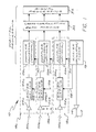
- a polystatic correlating radar 10 includes one or more transmitters including a transmitter antenna 12, and a transmitter amplifier 14 for amplifying a radar signal received from a master oscillator and clock 16 for transmission by the transmitter antenna.
- one preferred radar carrier wave is electromagnetic energy having wavelengths from one centimeter to one millimeter, and frequencies from 30 GHz to 300 GHz. Millimeter waves are advantageous in having a large bandwidth, and in having a short characteristic wavelength, allowing a small antenna size. In addition, this region of the spectrum is not widely used. This reduces the likelihood of mutual interference between radar systems. Attenuation of millimeter waves in the atmosphere can also be advantageous in minimizing the probability of mutual interference between radar systems.
- other forms and spectra of electromagnetic energy may also be used, much as acoustic waves for sonar, which is useful in limited range operation.
- the wave energy reflected from a target is received by a plurality of radar receivers 18a, 18b, 18c, each including a receiver antenna 20a, 20b, 20c, an amplifier 22a, 22b, 22c, and range gating circuitry 24a, 24b, 24c.
- Doppler signal processing circuitry 26a, 26b, 26c may also be provided for determining radial velocity with respect to the receivers.
- the master clock and oscillator is in electrical communication with the range gating circuitry via line 28 and in communication with the Doppler processing circuitry via line 30.
- a cross correlation beam forming circuit 32 receives the output of the receivers for focusing the received radar signals and generating a map of objects in the field of the view, and is typically provided for in a digital processing unit.
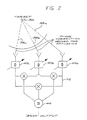
- the function of the cross correlation beam forming circuitry 32 is further illustrated in Fig. 2, as will be explained further below.
- the map defined by cross correlated beam outputs from the cross correlation unit 32 is received by the signal processing unit 34, for general tracking, identification and determination of false alarms concerning the object.
- the signal processing unit is capable of generating a complete two or three dimensional map of objects in the field of view, including range, angular location, radial velocity, tangential velocity, and radar cross section information.
- a signal code may be utilized by the transmitter for identification purposes, which can be recognized by the signal processing unit as well.
- the target 36 scatters the wave energy in the form of reflected radar beams 38a, 38b, 38c, to be received by the radar signal receiver units.
- the outputs of the multiple radar receivers are cross correlated to obtain a narrow beam response.
- This correlation beam forming process is performed for each angle at which resolution is desired.
- the cross correlation beam forming process consists of the steps of correcting the phase of the signal received from each receiver, based upon the desired focal point, either two or three dimensional. Additionally, the amplitude of the received signal may be corrected.
- the phase and amplitude of the received signals are corrected in the phase correction units 40a, 40b, 40c.
- the output from the phase correction units is cross correlated among all of the receiver phase correction units, as illustrated by the lines 42, and is directed to a summer 44 to sum all of the cross correlation products between each of the phase correction units.
- this process is completely general, and is applicable to both far field and near field operation.
- the radar system performs Doppler processing to determine range rate
- the cross correlation beam forming process must be performed after the Doppler processing.
- the use of multiple receivers will generate multiple range rate measurements from various angles for any given target.
- Application of vector algebra in the signal processing unit will then yield an estimate of the tangential velocity, and thus of the total velocity vector, for that object.
- the accuracy of the tangential velocity estimate degrades with increasing range, since the angle between the several radial velocity measurements decreases with range. Thus, this determination is most accurate with close targets.
- improved radial velocity resolution with respect to each receiver will improve the overall tangential velocity estimate.
- the transmitter of the radar system can also provide additional scan capabilities.
- the correlation beam forming process typically generates significant grating lobes.
- the directional transmit beam is then used to cut off or eliminate all but one lobe (typically the center lobe) which is then scanned, by the cross-correlation beam forming unit, within the transmit coverage.
- the transmit beam is then used to select an alternate correlation lobe, this alternate coverage will be scanned in place of the center lobe.
- a side total coverage is possible, at the expense of a small increase in transmitter complexity.
- the transmit beam scanning may be accomplished by any of several means. Scanning may involve frequency scanning, and Butler-matrix beam forming, although other forms of scanning may also be used. Frequency scanning would require only a simple travelling wave antenna and a voltage controlled local oscillator, which would be shared by the transmit and receive portions of the radar system.
- the Butler-matrix approach involves a complexity of hardware, but involves simply changing feed ports to select alternate transmit coverage.
- the polystatic correlating radar of the invention is advantageous in providing improved resolution to obtain narrow beam response, and for providing a close range radar system, which can provide not only angular location, range, and radial rate information, but also tangential velocity information about the target.
Abstract
Description
- This invention relates generally to correlating radiometer techniques, in combination with standard radar techniques for providing high resolution angular location and range gating measurements, and more particularly relates to polystatic cross correlating radar techniques useful for object angular location, ranging, and radial velocity and tangential velocity measurements for close targets, useful for automotive collision avoidance radar, cruise control radar, and self-mobile robotic systems.
- In general, conventional radar devices include a transmitting antenna emitting electromagnetic radiation generated by an oscillator, a receiving antenna, and an energy detecting receiver. The receiver provides a received radar signal to a signal processing unit where the radar signals are processed to detect and identify the presence of a target, and to determine its location and radial velocity with respect to the receiver. Distance can be determined by measuring the time taken for the radar signal to travel to the target and to return. The direction, or angular location of the target may be determined by the direction of arrival of the received radar signal. Directional information is usually obtained with narrow antenna beams, and the radial velocity of the target with reference to the receiver can be measured by detecting shifts in the carrier frequency of the radar signal reflected from the target, commonly known as the Doppler effect. Continuous waveforms can be used to take advantage of the Doppler frequency shift, and frequency or phase modulation of the continuous waveform permits range measurements from the received radar signals.
- Modern radar typically uses a common antenna for both transmitting and receiving, known as monostatic radar. A bistatic radar is one in which the transmitting and receiving antennae are separated by a given distance. In early experimental radar systems this was known as CW wave-interference radar. Such early experimental radar systems utilized continuous waveform (CW) radar signals, and depended for detection upon interference produced between the signal received directly from the transmitter and the Doppler frequency shifted signal reflected by a target.
- When several separate receivers are employed with a signal transmitter, the radar system is known as multistatic, or polystatic radar. An essential feature of the bistatic or polystatic radar is that the radiated signal from the transmitter arrives at the receivers from the scattered path which includes the target, and is also directly correlated with the receiver in a direct path from the transmitter. Information from the transmitted signal allows extraction of information from the scattered signal. Thus, from the transmitted frequency, the Doppler frequency shift, and the phase or time shift may also be determined. Although a bistatic radar can be operated with either pulse modulation or continuous waveform energy, continuous wave radar requires considerable isolation between the transmitter and receiver, which is obtainable in a bistatic or polystatic radar because of inherent separation between the transmitter and receivers.
- Continuous wave radar also may be used for determining range if a timing mark is applied to the CW carrier, permitting the time of transmission and time of return to be recognized. Such a timing mark is applied to the CW carrier, permitting the time of transmission and time of return to be recognized. Such a timing mark can be used for identifying the transmitted carrier as well. A widely used technique to allow a broad spectrum of radar and timing information is frequency modulation of the carrier (FM-CW).
- Another conventional radar technique for obtaining information from a received radar signal is the process of range gating. Each range gate opens sequentially just long enough to sample the received signal corresponding to a different range of time corresponding to a distance of travel of the signal in space.
- If the bandwidth of the receiver pass bank is wide compared with that of the received signal energy, extraneous noise is introduced, reducing the signal to noise ratio of the received signal. If the receiver bandwidth is narrower than the bandwidth of the received signal, noise energy is reduced, along with a considerable portion of the received signal energy. This also reduces the signal to noise ratio. A matched filter functions to maximize the output peak signal to mean noise ratio. A matched filter receiver can be replaced by a cross correlation receiver that performs the same operation. In a cross correlation receiver, an input signal is multiplied by a delayed replica of the transmitted signal, and the product is passed through a low pass filter to perform integration of the signal. It would be desirable to combine such radar techniques to permit high resolution location and range and radial velocity measurements, as well as tangential velocity measurements of a close target. The present invention addresses this need.
- The present invention provides for a polystatic correlating radar for detecting and locating an object at close ranges. A plurality of radar receivers receive a signal reflected from the object from one or more radar signal transmitters. Signals received from the plurality of receivers are cross correlated to provide high resolution of the angular location, range, and radial velocity measurements, as well as tangential velocity measurements for close targets. The polystatic correlating radar of the invention can, for example, be used to implement a full performance collision avoidance/mitigation radar system. The system utilizes a polystatic radar front end to achieve high range and rate resolution, and to minimize false alarms.
- Briefly, and in general terms, a polystatic correlating radar according to the invention includes at least one means for transmitting a radar signal, a plurality of radar receivers including means for range gating the received signal, means for cross correlating the radar signal received by the receivers, and signal processing means for determining the angular location and the radial range of the object. In a preferred embodiment, the receivers also include Doppler processing means, and the signal processing means includes means for determining the tangential velocity of the target.
- Other aspects and advantages of the invention will become apparent from the following detailed description, and the accompanying drawings illustrating by way of example the features.
-
- FIGURE 1 is a schematic block diagram of a polystatic correlating radar system; and
- FIG. 2 is a block diagram illustrating the steps of cross correlating the received radar signals.
- As is shown in the drawings for purposes of illustration, the invention is embodied in an apparatus and a method for detecting and locating an object by polystatic correlating radar. The object to be detected is illuminated with wave radiation which is reflected from the object to a plurality of receivers which include means for determining the range of the object from the receivers. Means are provided for correlation beam forming the radar signal received by the receivers to provide corrected signals between all of the receivers to obtain the angular location with a narrow beam response. A signal processing unit receives the corrected beam output to determine the angular location and radial range of the target, and in a preferred embodiment also to determine the tangential velocity of the target. Doppler processing is also provided in the preferred embodiment for determining the radial velocity. In a preferred embodiment, the correlation beam forming is performed by correcting the phase of the signal received from each of the receivers, determining the cross correlation products of the corrected signals between all of the elements, and summing of the cross correlation products to provide the corrected, cross correlated beam output. Further signal processing techniques may be optionally utilized in transmitting the radar signal, and on the cross correlated beam output for improvement of the detection and location of the target.
- In accordance with the invention, there is therefore provided a polystatic correlating radar apparatus for detecting and locating an object, comprising at least one means for transmitting a radar signal; a plurality of radar signal receivers, including means synchronized with the transmitted radar signal for range gating a received radar signal for determining the range of the object from the receivers; means for cross correlating the radar signal received by each of the plurality of the receivers between each of the receivers to provide corrected received radar signals from all of the receivers; and signal processing means in electrical communication with the means for cross correlating the radar signals, for determining the angular location and the radial range of the object from the receivers.
- The invention also provides for a method for correlating polystatic radar for detecting and locating an object, comprising the steps of transmitting a radar signal; receiving a radar signal reflected from said object at a plurality of receivers, and synchronizing with the transmitted radar signal for range gating each of said received radar signals; cross correlating the receiver signal output between each of said receivers; and signal outputs to determine the angular location and range of said object.
- As is shown in the drawings, a
polystatic correlating radar 10 includes one or more transmitters including a transmitter antenna 12, and atransmitter amplifier 14 for amplifying a radar signal received from a master oscillator and clock 16 for transmission by the transmitter antenna. Although conventional radar transmission frequencies may be used, one preferred radar carrier wave is electromagnetic energy having wavelengths from one centimeter to one millimeter, and frequencies from 30 GHz to 300 GHz. Millimeter waves are advantageous in having a large bandwidth, and in having a short characteristic wavelength, allowing a small antenna size. In addition, this region of the spectrum is not widely used. This reduces the likelihood of mutual interference between radar systems. Attenuation of millimeter waves in the atmosphere can also be advantageous in minimizing the probability of mutual interference between radar systems. Alternatively, other forms and spectra of electromagnetic energy may also be used, much as acoustic waves for sonar, which is useful in limited range operation. - The wave energy reflected from a target is received by a plurality of radar receivers 18a, 18b, 18c, each including a
receiver antenna amplifier range gating circuitry line 28 and in communication with the Doppler processing circuitry vialine 30. - A cross correlation
beam forming circuit 32 receives the output of the receivers for focusing the received radar signals and generating a map of objects in the field of the view, and is typically provided for in a digital processing unit. The function of the cross correlationbeam forming circuitry 32 is further illustrated in Fig. 2, as will be explained further below. The map defined by cross correlated beam outputs from thecross correlation unit 32 is received by thesignal processing unit 34, for general tracking, identification and determination of false alarms concerning the object. The signal processing unit is capable of generating a complete two or three dimensional map of objects in the field of view, including range, angular location, radial velocity, tangential velocity, and radar cross section information. A signal code may be utilized by the transmitter for identification purposes, which can be recognized by the signal processing unit as well. - Referring to Fig. 2, the target 36 scatters the wave energy in the form of reflected radar beams 38a, 38b, 38c, to be received by the radar signal receiver units. In the preferred mode of the invention, the outputs of the multiple radar receivers are cross correlated to obtain a narrow beam response. This correlation beam forming process is performed for each angle at which resolution is desired. The cross correlation beam forming process consists of the steps of correcting the phase of the signal received from each receiver, based upon the desired focal point, either two or three dimensional. Additionally, the amplitude of the received signal may be corrected. The phase and amplitude of the received signals are corrected in the
phase correction units lines 42, and is directed to asummer 44 to sum all of the cross correlation products between each of the phase correction units. - As a result of the initial correction of the data of the focal point, this process is completely general, and is applicable to both far field and near field operation. If the radar system performs Doppler processing to determine range rate, the cross correlation beam forming process must be performed after the Doppler processing. The use of multiple receivers will generate multiple range rate measurements from various angles for any given target. Application of vector algebra in the signal processing unit will then yield an estimate of the tangential velocity, and thus of the total velocity vector, for that object. The accuracy of the tangential velocity estimate degrades with increasing range, since the angle between the several radial velocity measurements decreases with range. Thus, this determination is most accurate with close targets. Similarly, improved radial velocity resolution with respect to each receiver will improve the overall tangential velocity estimate.
- It should be understood that the transmitter of the radar system can also provide additional scan capabilities. The correlation beam forming process typically generates significant grating lobes. The directional transmit beam is then used to cut off or eliminate all but one lobe (typically the center lobe) which is then scanned, by the cross-correlation beam forming unit, within the transmit coverage. However, if the transmit beam is then used to select an alternate correlation lobe, this alternate coverage will be scanned in place of the center lobe. Thus, a side total coverage is possible, at the expense of a small increase in transmitter complexity.
- The transmit beam scanning may be accomplished by any of several means. Scanning may involve frequency scanning, and Butler-matrix beam forming, although other forms of scanning may also be used. Frequency scanning would require only a simple travelling wave antenna and a voltage controlled local oscillator, which would be shared by the transmit and receive portions of the radar system. The Butler-matrix approach involves a complexity of hardware, but involves simply changing feed ports to select alternate transmit coverage.
- In view of the foregoing, it has been demonstrated that the polystatic correlating radar of the invention is advantageous in providing improved resolution to obtain narrow beam response, and for providing a close range radar system, which can provide not only angular location, range, and radial rate information, but also tangential velocity information about the target.
- Although a specific embodiment of the invention has been described and illustrated, it is clear that it is susceptible to numerous modifications and adaptations within the ability of those skilled in the art and without the exercise of the inventive faculty. Thus, it should be understood that various changes in form, detail and use of the present invention may be made without departing from the spirit and scope of this invention.
Claims (16)
- A polystatic correlating radar apparatus for detecting and locating an object, comprising at least one means for transmitting a radar signal;
a plurality of radar signal receivers, including means for correlating said transmitted radar signal with a received signal for range gating said received radar signal for determining the range of said object from said receivers;
means for cross correlating the radar signal received by each of said plurality of said receivers with each said receiver to provide corrected received radar signals from all of said receivers;
signal processing means in electrical communication with said means for cross correlating said radar signals, for determining the angular location and the radial range of said object from said receivers. - The apparatus of Claim 1, wherein said means for cross correlating includes means for correcting the phase of the signal received from each of said receivers, means for determining the cross correlation product of the corrected signals between all of the receivers, and means for summing said cross correlation products to provide a corrected receiver signal, whereby said polystatic correlating radar apparatus is enabled to determine the angular location with a narrow beam response.
- The apparatus of Claim 1, wherein each of said radar receivers includes means for determining a Doppler frequency shift of said receiver signal.
- The apparatus of Claim 1, wherein said signal processing means includes means for determining the tangential velocity of said object relative to said receivers.
- The apparatus of Claim 1, wherein said means for transmitting a radar signal includes means for scanning the frequency; of said transmitted radar signal.
- A method for correlating polystatic radar for detecting and locating an object, comprising the steps of:
transmitting a radar signal;
receiving said radar signal reflected from said object at a plurality of receivers, and range gating said received radar signal from each of said receivers;
cross correlating the receiver signal output between each of said receivers; and
processing said cross correlated receiver signal outputs to determine the angular location and range of said object. - The method of Claim 6, wherein said step of cross correlating said receiver signal outputs comprises correcting the phase of said signals received from each of receivers to focus said received signals, determining the cross correlation product of the corrected signals between each of said receivers, and summing said cross correlation products to determine the angular location with a narrow beam response.
- The method of Claim 6, further including the step of determining the tangential velocity of said object responsive to said cross correlated receiver output.
- The method of Claim 6, further including the step of determining the Doppler frequency shift of said received radar signal from each of said receivers.
- The method of Claim 6, wherein said step of transmitting includes scanning said transmitted radar signal.
- The method of Claim 6, wherein said step of transmitting further includes the step of beam shaping said transmitted radar signal.
- The method of Claim 6, wherein said step of transmitting a radar signal comprises illuminating said object with millimeter wave radiation.
- The method of Claim 6, wherein said step of transmitting comprises identifying said transmitted radar signal with a signal code.
- The method of Claim 13, wherein said step of receiving further includes identifying a transmitted signal from characteristics of said signal code.
- The method of Claim 6, wherein said step of cross correlating said receiver outputs includes the step of processing said received signals with said transmitted radar signal to select a lobe of said received radar signals and to substantially eliminate other lobes of the signal.
- The method of Claim 8, wherein said step of determining the tangential velocity of said object comprises sequentially determining the location of said object and determining tangential velocity by vector algebra.
Applications Claiming Priority (2)
| Application Number | Priority Date | Filing Date | Title |
|---|---|---|---|
| US07/490,032 US4994809A (en) | 1990-03-07 | 1990-03-07 | Polystatic correlating radar |
| US490032 | 1990-03-07 |
Publications (3)
| Publication Number | Publication Date |
|---|---|
| EP0446678A2 true EP0446678A2 (en) | 1991-09-18 |
| EP0446678A3 EP0446678A3 (en) | 1993-04-07 |
| EP0446678B1 EP0446678B1 (en) | 1998-01-21 |
Family
ID=23946333
Family Applications (1)
| Application Number | Title | Priority Date | Filing Date |
|---|---|---|---|
| EP91102466A Expired - Lifetime EP0446678B1 (en) | 1990-03-07 | 1991-02-20 | Polystatic correlating radar |
Country Status (5)
| Country | Link |
|---|---|
| US (1) | US4994809A (en) |
| EP (1) | EP0446678B1 (en) |
| JP (1) | JP2651054B2 (en) |
| CA (1) | CA2035811C (en) |
| DE (1) | DE69128734T2 (en) |
Cited By (3)
| Publication number | Priority date | Publication date | Assignee | Title |
|---|---|---|---|---|
| CN1057297C (en) * | 1993-09-10 | 2000-10-11 | 第一制药株式会社 | Crystals of antimicrobial compound |
| EP1111811A2 (en) * | 1999-12-21 | 2001-06-27 | Texas Instruments Incorporated | Wireless communication system with Doppler diversity |
| WO2003081278A1 (en) * | 2002-03-27 | 2003-10-02 | Robert Bosch Gmbh | Device for, in particular, bistatic radar applications |
Families Citing this family (69)
| Publication number | Priority date | Publication date | Assignee | Title |
|---|---|---|---|---|
| GB2257323B (en) * | 1991-06-27 | 1995-03-08 | Commw Of Australia | Auto-correlation technique for co-ordinate registration |
| US5252980A (en) * | 1992-07-23 | 1993-10-12 | The United States Of America As Represented By The Secretary Of The Air Force | Target location system |
| US5381156A (en) * | 1993-04-15 | 1995-01-10 | Calspan Corporation | Multiple target doppler tracker |
| US5410314A (en) * | 1993-11-30 | 1995-04-25 | University Corporation For Atmospheric Research | Bistatic multiple-doppler radar network |
| US5623267A (en) * | 1993-11-30 | 1997-04-22 | Wurman; Joshua M. A. R. | Wide-angle multiple-doppler radar network |
| US5434570A (en) * | 1993-11-30 | 1995-07-18 | Wurman; Joshua M. A. R. | Wide-angle multiple-doppler radar network |
| US5497162A (en) * | 1995-01-09 | 1996-03-05 | Northrop Grumman Corporation | Radar signal selection based upon antenna bearing |
| US6011487A (en) * | 1996-09-17 | 2000-01-04 | Ncr Corporation | System and method of locating wireless devices |
| US6377208B2 (en) | 1997-02-21 | 2002-04-23 | Hughes Electronics Corporation | Method and system for determining a position of a transceiver unit utilizing two-way ranging in a polystatic satellite configuration |
| DE69830936T2 (en) | 1997-02-21 | 2006-04-20 | Hughes Electronics Corp., El Segundo | Method and device for determining the position of the transceiver system by means of two-way distance determination in a polystatic satellite configuration with ground radar |
| GB2333198B (en) * | 1998-01-12 | 2002-12-24 | Roke Manor Research | Threat detection apparatus |
| US6229477B1 (en) | 1998-10-16 | 2001-05-08 | Hughes Electronics Corporation | Method and system for determining a position of a communication satellite utilizing two-way ranging |
| US7089000B1 (en) | 1999-03-18 | 2006-08-08 | The Directv Group, Inc. | Multi-node wireless communication system with multiple transponding platforms |
| US6337980B1 (en) | 1999-03-18 | 2002-01-08 | Hughes Electronics Corporation | Multiple satellite mobile communications method and apparatus for hand-held terminals |
| US6785553B2 (en) | 1998-12-10 | 2004-08-31 | The Directv Group, Inc. | Position location of multiple transponding platforms and users using two-way ranging as a calibration reference for GPS |
| US6246363B1 (en) | 1998-12-10 | 2001-06-12 | Hughes Electronics Corporation | Method and system for incorporating two-way ranging navigation as a calibration reference for GPS |
| US6990314B1 (en) | 1999-03-18 | 2006-01-24 | The Directv Group, Inc. | Multi-node point-to-point satellite communication system employing multiple geo satellites |
| US6920309B1 (en) | 1999-03-18 | 2005-07-19 | The Directv Group, Inc. | User positioning technique for multi-platform communication system |
| AU4393300A (en) * | 1999-05-10 | 2000-11-21 | B-K Medical A/S | Vector velocity estimation using directional beam forming and cross-correlation |
| US6963548B1 (en) | 2000-04-17 | 2005-11-08 | The Directv Group, Inc. | Coherent synchronization of code division multiple access signals |
| KR100791239B1 (en) | 2000-04-24 | 2008-01-03 | 록히드 마틴 코포레이션 | Passive coherent location system and method |
| US6388615B1 (en) * | 2000-06-06 | 2002-05-14 | Hughes Electronics Corporation | Micro cell architecture for mobile user tracking communication system |
| US6756937B1 (en) | 2000-06-06 | 2004-06-29 | The Directv Group, Inc. | Stratospheric platforms based mobile communications architecture |
| AU2001288273A1 (en) * | 2000-08-16 | 2002-02-25 | Raytheon Company | Video amplifier for a radar receiver |
| US20020075138A1 (en) * | 2000-08-16 | 2002-06-20 | Van Rees H. Barteld | Portable object detection system |
| WO2002014891A2 (en) * | 2000-08-16 | 2002-02-21 | Raytheon Company | Automotive radar systems and techniques |
| KR100767543B1 (en) * | 2000-08-16 | 2007-10-17 | 레이던 컴퍼니 | Switched beam antenna architecture |
| EP1309882B1 (en) * | 2000-08-16 | 2004-12-08 | Raytheon Company | Near object detection system |
| JP2004505844A (en) * | 2000-08-16 | 2004-02-26 | レイセオン・カンパニー | Safe distance algorithm for adaptive cruise control |
| US6577269B2 (en) | 2000-08-16 | 2003-06-10 | Raytheon Company | Radar detection method and apparatus |
| US7257418B1 (en) | 2000-08-31 | 2007-08-14 | The Directv Group, Inc. | Rapid user acquisition by a ground-based beamformer |
| US6941138B1 (en) | 2000-09-05 | 2005-09-06 | The Directv Group, Inc. | Concurrent communications between a user terminal and multiple stratospheric transponder platforms |
| DE60123640T2 (en) * | 2000-09-08 | 2007-08-16 | Raytheon Company, Waltham | METHOD AND DEVICE FOR PREDICTION OF A PATH |
| US7046718B1 (en) | 2000-09-25 | 2006-05-16 | The Directv Group, Inc. | Coherent phase synchronous code division multiple access communications from multiple transponder platforms |
| IL155513A0 (en) * | 2000-10-20 | 2003-11-23 | Lockheed Corp | Civil aviation passive coherent location system and method |
| US20020073437A1 (en) * | 2000-12-12 | 2002-06-13 | Hughes Electronics Corporation | Television distribution system using multiple links |
| US7181162B2 (en) | 2000-12-12 | 2007-02-20 | The Directv Group, Inc. | Communication system using multiple link terminals |
| US7400857B2 (en) * | 2000-12-12 | 2008-07-15 | The Directv Group, Inc. | Communication system using multiple link terminals |
| US7103317B2 (en) * | 2000-12-12 | 2006-09-05 | The Directv Group, Inc. | Communication system using multiple link terminals for aircraft |
| US6891813B2 (en) * | 2000-12-12 | 2005-05-10 | The Directv Group, Inc. | Dynamic cell CDMA code assignment system and method |
| US7068733B2 (en) * | 2001-02-05 | 2006-06-27 | The Directv Group, Inc. | Sampling technique for digital beam former |
| US6559797B1 (en) | 2001-02-05 | 2003-05-06 | Hughes Electronics Corporation | Overlapping subarray patch antenna system |
| US6708100B2 (en) * | 2001-03-14 | 2004-03-16 | Raytheon Company | Safe distance algorithm for adaptive cruise control |
| US6710743B2 (en) * | 2001-05-04 | 2004-03-23 | Lockheed Martin Corporation | System and method for central association and tracking in passive coherent location applications |
| JP2004537040A (en) | 2001-05-04 | 2004-12-09 | ロッキード・マーティン・コーポレイション | System and method for processing wideband pre-detection signals for passive coherent search applications |
| WO2002091017A2 (en) | 2001-05-04 | 2002-11-14 | Lockheed Martin Corporation | System and method for measurement domain data association in passive coherent location applications |
| DK1384092T3 (en) | 2001-05-04 | 2011-06-14 | Lockheed Corp | System and method for detecting extraction of characteristics at passive coherent location |
| US6703968B2 (en) | 2001-05-04 | 2004-03-09 | Lockheed Martin Corporation | System and method for mitigating co-channel interference in passive coherent location applications |
| SE519089C2 (en) * | 2001-05-11 | 2003-01-07 | Totalfoersvarets Forskningsins | Systems for sending signals from targets to determine locations and speeds for the targets |
| US6995730B2 (en) * | 2001-08-16 | 2006-02-07 | Raytheon Company | Antenna configurations for reduced radar complexity |
| US7183995B2 (en) | 2001-08-16 | 2007-02-27 | Raytheon Company | Antenna configurations for reduced radar complexity |
| US6970142B1 (en) | 2001-08-16 | 2005-11-29 | Raytheon Company | Antenna configurations for reduced radar complexity |
| JP4713083B2 (en) * | 2002-02-08 | 2011-06-29 | ロッキード・マーティン・コーポレイション | How to track flying debris |
| US6661740B1 (en) | 2002-06-03 | 2003-12-09 | Ben R. Breed | Multi-static, opportune-source-exploiting, passive sonar processing |
| US6611227B1 (en) | 2002-08-08 | 2003-08-26 | Raytheon Company | Automotive side object detection sensor blockage detection system and related techniques |
| DE10252091A1 (en) * | 2002-11-08 | 2004-05-19 | Siemens Ag | Multi-static sensor arrangement for object distance measurement, e.g. for vehicle parking, has pulse generators receiving clock signals via common data bus to produce deterministic HF oscillator signal phase relationship |
| US20070176822A1 (en) * | 2006-01-30 | 2007-08-02 | Fujitsu Limited | Target detection apparatus and system |
| EP1982212A4 (en) * | 2006-02-09 | 2010-12-15 | Ericsson Telefon Ab L M | A radar system comprising at least two spatially separated antenna units |
| DE102006039517A1 (en) * | 2006-08-23 | 2008-03-06 | Siemens Ag | Method for operating a radar system and radar system |
| US7609198B2 (en) * | 2007-05-21 | 2009-10-27 | Spatial Digital Systems, Inc. | Apparatus and method for radar imaging by measuring spatial frequency components |
| KR101191293B1 (en) * | 2008-03-31 | 2012-10-16 | 발레오 레이더 시스템즈, 인크. | Automotive radar sensor blockage detection apparatus and method |
| US8279109B1 (en) * | 2009-03-30 | 2012-10-02 | Gregory Hubert Piesinger | Aircraft bird strike avoidance method and apparatus using transponder |
| FR2945636B1 (en) * | 2009-05-15 | 2016-11-11 | Thales Sa | OPTIMIZED MULTISTATIC MONITORING SYSTEM |
| DE102013015454A1 (en) * | 2013-09-18 | 2015-03-19 | Mbda Deutschland Gmbh | Networked multistatic radar receiving device |
| JP6716223B2 (en) * | 2015-09-09 | 2020-07-01 | 株式会社東芝 | Radar system and signal processing system |
| US11520030B2 (en) | 2019-03-18 | 2022-12-06 | Nxp Usa, Inc. | High resolution automotive radar system with forward and backward difference co-array processing |
| US11269049B2 (en) | 2019-03-18 | 2022-03-08 | Nxp Usa, Inc. | Distributed aperture automotive radar system |
| US11092683B2 (en) | 2019-03-18 | 2021-08-17 | Nxp Usa, Inc. | Distributed aperture automotive radar system with alternating master radar devices |
| US11888554B2 (en) | 2020-09-23 | 2024-01-30 | Nxp Usa, Inc. | Automotive MIMO radar system using efficient difference co-array processor |
Citations (1)
| Publication number | Priority date | Publication date | Assignee | Title |
|---|---|---|---|---|
| US4499468A (en) * | 1982-04-21 | 1985-02-12 | The United States Of America As Represented By The Secretary Of The Air Force | Range-only multistatic radar system |
Family Cites Families (8)
| Publication number | Priority date | Publication date | Assignee | Title |
|---|---|---|---|---|
| GB810975A (en) * | 1955-03-14 | 1959-03-25 | Decca Record Co Ltd | Improvements in or relating to radio antennae systems |
| US3889266A (en) * | 1959-01-22 | 1975-06-10 | Dewey Electronics Corp | Multiple correlation method and apparatus for measuring and summing time differences |
| US3154778A (en) * | 1959-07-31 | 1964-10-27 | Bendix Corp | Method and apparatus for obtaining directional locating and detecting characteristics with reduced antenna size |
| US3134977A (en) * | 1960-10-06 | 1964-05-26 | Nippon Electric Co | Wave source position detecting system |
| US3812493A (en) * | 1970-11-23 | 1974-05-21 | Us Navy | Bistatic passive radar |
| FR2408842A1 (en) * | 1977-11-10 | 1979-06-08 | Trt Telecom Radio Electr | AIRPORT OBSTACLE DETECTOR DEVICE |
| US4305074A (en) * | 1980-05-12 | 1981-12-08 | The United States Of America As Represented By The Secretary Of The Army | Electromagnetic detection apparatus |
| US4901084A (en) * | 1988-04-19 | 1990-02-13 | Millitech Corporation | Object detection and location system |
-
1990
- 1990-03-07 US US07/490,032 patent/US4994809A/en not_active Expired - Lifetime
-
1991
- 1991-02-06 CA CA002035811A patent/CA2035811C/en not_active Expired - Lifetime
- 1991-02-20 DE DE69128734T patent/DE69128734T2/en not_active Expired - Fee Related
- 1991-02-20 EP EP91102466A patent/EP0446678B1/en not_active Expired - Lifetime
- 1991-03-06 JP JP3065622A patent/JP2651054B2/en not_active Expired - Lifetime
Patent Citations (1)
| Publication number | Priority date | Publication date | Assignee | Title |
|---|---|---|---|---|
| US4499468A (en) * | 1982-04-21 | 1985-02-12 | The United States Of America As Represented By The Secretary Of The Air Force | Range-only multistatic radar system |
Non-Patent Citations (1)
| Title |
|---|
| L' ONDE ELECTRIQUE vol. 69, no. 6, November 1989, PARIS , FR pages 36 - 44 , XP73623 J. DOREY AND G. GARNIER 'RIAS , Radar a Impulsions et Antenne Synthetique' * |
Cited By (5)
| Publication number | Priority date | Publication date | Assignee | Title |
|---|---|---|---|---|
| CN1057297C (en) * | 1993-09-10 | 2000-10-11 | 第一制药株式会社 | Crystals of antimicrobial compound |
| EP1111811A2 (en) * | 1999-12-21 | 2001-06-27 | Texas Instruments Incorporated | Wireless communication system with Doppler diversity |
| EP1111811A3 (en) * | 1999-12-21 | 2003-07-02 | Texas Instruments Incorporated | Wireless communication system with Doppler diversity |
| WO2003081278A1 (en) * | 2002-03-27 | 2003-10-02 | Robert Bosch Gmbh | Device for, in particular, bistatic radar applications |
| US7109916B2 (en) | 2002-03-27 | 2006-09-19 | Robert Bosch Gmbh | Device for, in particular bistatic radar applications |
Also Published As
| Publication number | Publication date |
|---|---|
| EP0446678A3 (en) | 1993-04-07 |
| DE69128734T2 (en) | 1998-04-30 |
| CA2035811A1 (en) | 1991-09-08 |
| DE69128734D1 (en) | 1998-02-26 |
| EP0446678B1 (en) | 1998-01-21 |
| US4994809A (en) | 1991-02-19 |
| CA2035811C (en) | 1994-10-04 |
| JP2651054B2 (en) | 1997-09-10 |
| JPH04220582A (en) | 1992-08-11 |
Similar Documents
| Publication | Publication Date | Title |
|---|---|---|
| US4994809A (en) | Polystatic correlating radar | |
| US5784026A (en) | Radar detection of accelerating airborne targets | |
| US4746924A (en) | Apparatus and methods for locating a target utilizing signals generated from a non-cooperative source | |
| KR100645771B1 (en) | Radar | |
| EP1254381B1 (en) | Precision radar altimeter with terrain feature coordinate location capability | |
| EP2330437B1 (en) | Target detection apparatus and system | |
| US5726657A (en) | Phase coherent radar system using fast frequency agile waveform synthesis | |
| US20030090405A1 (en) | Spread spectrum radar with leak compensation at baseband | |
| US5923282A (en) | Radar system | |
| EP2182375A1 (en) | A combined direction finder and radar system, method and computer program product | |
| AU8302891A (en) | Monopulse processing systems | |
| EP1384092B1 (en) | System and method for detection and feature extraction in passive coherent location | |
| US5280294A (en) | Passive monopulse ranging to a non-cooperative emitter and non-emitting object | |
| US5559515A (en) | Channel switching interferometric AMTI radar | |
| US11709261B2 (en) | Radar device for vehicle, controlling method of radar device and radar system for vehicle | |
| US3270340A (en) | Method of echo grouping | |
| Samczynski et al. | Passive radars utilizing pulse radars as illuminators of opportunity | |
| US3992710A (en) | Target tracker having target recognition means | |
| US4060807A (en) | Low angle radar | |
| US4193074A (en) | Enhancing radar returns from targets having a small radar cross section | |
| US5247311A (en) | Loro antenna and pulse pattern detection system | |
| JPH0429080A (en) | Bistatic radar equipment | |
| Berle | Mixed triangulation/trilateration technique for emitter location | |
| JP3061738B2 (en) | Distance measuring apparatus and distance measuring method using multi-PRF method | |
| KR102156660B1 (en) | Apparatus and method for detecting velocity |
Legal Events
| Date | Code | Title | Description |
|---|---|---|---|
| PUAI | Public reference made under article 153(3) epc to a published international application that has entered the european phase |
Free format text: ORIGINAL CODE: 0009012 |
|
| AK | Designated contracting states |
Kind code of ref document: A2 Designated state(s): DE |
|
| PUAL | Search report despatched |
Free format text: ORIGINAL CODE: 0009013 |
|
| AK | Designated contracting states |
Kind code of ref document: A3 Designated state(s): DE |
|
| 17P | Request for examination filed |
Effective date: 19931006 |
|
| 17Q | First examination report despatched |
Effective date: 19950725 |
|
| GRAG | Despatch of communication of intention to grant |
Free format text: ORIGINAL CODE: EPIDOS AGRA |
|
| GRAG | Despatch of communication of intention to grant |
Free format text: ORIGINAL CODE: EPIDOS AGRA |
|
| GRAH | Despatch of communication of intention to grant a patent |
Free format text: ORIGINAL CODE: EPIDOS IGRA |
|
| GRAH | Despatch of communication of intention to grant a patent |
Free format text: ORIGINAL CODE: EPIDOS IGRA |
|
| GRAA | (expected) grant |
Free format text: ORIGINAL CODE: 0009210 |
|
| AK | Designated contracting states |
Kind code of ref document: B1 Designated state(s): DE |
|
| REF | Corresponds to: |
Ref document number: 69128734 Country of ref document: DE Date of ref document: 19980226 |
|
| PLBE | No opposition filed within time limit |
Free format text: ORIGINAL CODE: 0009261 |
|
| STAA | Information on the status of an ep patent application or granted ep patent |
Free format text: STATUS: NO OPPOSITION FILED WITHIN TIME LIMIT |
|
| 26N | No opposition filed | ||
| PGFP | Annual fee paid to national office [announced via postgrant information from national office to epo] |
Ref country code: DE Payment date: 20090331 Year of fee payment: 19 |
|
| PG25 | Lapsed in a contracting state [announced via postgrant information from national office to epo] |
Ref country code: DE Free format text: LAPSE BECAUSE OF NON-PAYMENT OF DUE FEES Effective date: 20100901 |