EP0446589B1 - ATM switch with copy capability - Google Patents
ATM switch with copy capability Download PDFInfo
- Publication number
- EP0446589B1 EP0446589B1 EP91101099A EP91101099A EP0446589B1 EP 0446589 B1 EP0446589 B1 EP 0446589B1 EP 91101099 A EP91101099 A EP 91101099A EP 91101099 A EP91101099 A EP 91101099A EP 0446589 B1 EP0446589 B1 EP 0446589B1
- Authority
- EP
- European Patent Office
- Prior art keywords
- switching matrix
- connections
- point
- cell
- exchange
- Prior art date
- Legal status (The legal status is an assumption and is not a legal conclusion. Google has not performed a legal analysis and makes no representation as to the accuracy of the status listed.)
- Expired - Lifetime
Links
- 239000000872 buffer Substances 0.000 claims description 44
- 239000011159 matrix material Substances 0.000 abstract description 79
- 230000008901 benefit Effects 0.000 abstract description 3
- 239000000470 constituent Substances 0.000 abstract 1
- 239000000203 mixture Substances 0.000 abstract 1
- 230000008707 rearrangement Effects 0.000 abstract 1
- 230000015654 memory Effects 0.000 description 54
- 238000010168 coupling process Methods 0.000 description 38
- 238000005859 coupling reaction Methods 0.000 description 38
- 230000008878 coupling Effects 0.000 description 37
- 230000008859 change Effects 0.000 description 4
- 230000009471 action Effects 0.000 description 2
- 230000001404 mediated effect Effects 0.000 description 2
- 230000000712 assembly Effects 0.000 description 1
- 238000000429 assembly Methods 0.000 description 1
- 230000009286 beneficial effect Effects 0.000 description 1
- 230000015572 biosynthetic process Effects 0.000 description 1
- 230000000903 blocking effect Effects 0.000 description 1
- 238000004891 communication Methods 0.000 description 1
- 238000010276 construction Methods 0.000 description 1
- 238000003745 diagnosis Methods 0.000 description 1
- 238000010586 diagram Methods 0.000 description 1
- 230000008030 elimination Effects 0.000 description 1
- 238000003379 elimination reaction Methods 0.000 description 1
- 238000005516 engineering process Methods 0.000 description 1
- 238000005259 measurement Methods 0.000 description 1
- 238000000034 method Methods 0.000 description 1
- 238000012986 modification Methods 0.000 description 1
- 230000004048 modification Effects 0.000 description 1
- 230000000737 periodic effect Effects 0.000 description 1
- 230000008569 process Effects 0.000 description 1
- 238000004088 simulation Methods 0.000 description 1
- 238000012546 transfer Methods 0.000 description 1
Images
Classifications
-
- H—ELECTRICITY
- H04—ELECTRIC COMMUNICATION TECHNIQUE
- H04Q—SELECTING
- H04Q11/00—Selecting arrangements for multiplex systems
- H04Q11/04—Selecting arrangements for multiplex systems for time-division multiplexing
-
- H—ELECTRICITY
- H04—ELECTRIC COMMUNICATION TECHNIQUE
- H04L—TRANSMISSION OF DIGITAL INFORMATION, e.g. TELEGRAPHIC COMMUNICATION
- H04L12/00—Data switching networks
- H04L12/02—Details
- H04L12/16—Arrangements for providing special services to substations
- H04L12/18—Arrangements for providing special services to substations for broadcast or conference, e.g. multicast
Definitions
- the invention relates to a copyable ATM switching center for switching ATM cells, according to the preamble of claim 1.
- Such an ATM switching center is known from WO 87/00372. Is further known a switching center with a sequence of copy switching matrix, Distribution switching matrix and target switching matrix.
- Real operation is a mix of both Point-to-point connections, Point-to-multipoint connections with few branches and point-to-multipoint connections with many Ramifications.
- the total traffic and the individual Shares change continuously.
- the well-known structures are only one-sided for a certain type of traffic optimized.
- the invention has for its object a to specify copyable ATM switch that various types of traffic, including those that change is equally adapted.
- the solution is based on the basic idea that Coupling elements of a switching matrix that for Point-to-point connections is optimized, in addition with the possibility to provide a few Copy input signals for any number of outputs, making a very high overall for a few input signals Number of copies can be reached.
- This main switching matrix will supplemented by a copy switching matrix that only making a limited number of copies serves for a large number of input signals which then in the main switching matrix as point-to-point connections mediated.
- Point-to-point connections are in the main switching matrix as "Connectionless connections” using self-control the coupling elements operated. It is ensured that these connections to the outside as virtual connections Act. Point-to-multipoint connections are also in the Main switching matrix as virtual connections (connection-oriented) using connection tables operated.
- connectionless connections Connections viewed in which the individual cells of a connection do not go the same way, but on all possible ways can be divided. This causes a fairly even load; on traffic measurements can be dispensed with, the otherwise necessary for this Devices are not required. But there is the need to be in the correct order of Cells to watch out for, because overtaking here is not excluded are.
- Coupled connections set coupling elements ahead by one contained in the route information Address can be controlled directly.
- the creation of Copies for point-to-multipoint connections is by means of such addressing is very difficult. Examples of such coupling elements are known.
- Coupling elements are also known, through indirect Addressing can be controlled. Come as route information connection numbers in question in each Coupling element evaluated using connection tables will. Is a connection number in the Connection table of a coupling element for several Contains outputs, so there is one at each of these outputs Copy of a cell with this connection number spent.
- connection numbers for Forces point-to-multipoint connections in the main switching matrix on special precautions if a Connection number should be used several times. On in any case is the total number in the main switching matrix possible point-to-multipoint connections are limited. Therefore but could on such Point-to-multipoint connection basically all of that Leaving the main switching network.
- the copy switching matrix has only the task that make the required number of copies.
- the These copies are mediated in the main switching matrix each in the manner of a point-to-point connection. Not each output of the copy switching network must be from each of its Inputs can be reached.
- the number of stages only depends on the copying ability of the individual coupling elements (i.e., on the number of outputs of the coupling elements) and on the the maximum number of copies required. Usually enough a copy switching matrix with a few steps (e.g. two to three-stage with 16X16 coupling elements). Each The connection number can be used several times here; the number of connections possible at the same time Copy switching matrix is therefore hardly any restrictions subject.
- a switching center constructed in this way can be of any kind Edit traffic.
- Local internal blockages can either do not occur (point-to-point connections) or be resolved at any time without interference (Point-to-multipoint connections). Even between the two possibilities of point-to-multipoint connections can be switched at any time without interference to the Adapt utilization to the current situation. In order to can be a very even utilization of the Main switching matrix can be reached. A partial one Blocking due to fully utilized customer lines or a load that is too high overall cannot be prevented.
- Group 31 contains i input units 311, 312, ..., 31i; the Group 32 contains j input units 321, 322, ..., 32j; group 33 contains k input units 331, 332, ..., 33k; group 41 contains 1 output units 411, 412, ..., 41l; group 42 contains k output units 421, 422, ..., 42k; group 43 contains j output units 431, 432, ..., 43j.
- Each of the inputs I1, I2, ..., Ii of the exchange is connected to the input of one of the input units 311, 312, ..., 31i connected to group 31, the outputs of each are connected to an input of the main switching matrix 10.
- Each of the outputs O1, O2, ..., Ol of the exchange is connected to the output of one of the output units 411, 412, ..., 41l of group 41 connected, the inputs of each are connected to an output of the switching matrix 10.
- the inputs of the output units 421, 422, ..., 42k of the Group 42 are with further outputs of the Main switching matrix 10 connected.
- the outputs of the Output units 421, 422, ..., 42k of group 42 are each with the input of one of the input units 331, 332, ..., 33k connected to group 33, the outputs of which Inputs of the switching matrix 20 are connected.
- the inputs of the output units 431, 432, ..., 43j the Group 43 are each with an output of the copy switching matrix 20 connected.
- the outputs of the output units 431, 432, ..., 43j of group 43 are each with the entrance one of the input units 321, 322, ..., 32j of the group 32 connected, the outputs of which are connected to further inputs of the Main switching matrix 10 are connected.
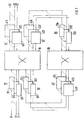
- the main switching matrix 10 contains a plurality of in coupling elements arranged in several stages. It is so established that connections between each input and any exit are possible. Examples of such Coupling fields are familiar to any specialist.
- the individual coupling elements are constructed so that they switchable by information contained in the cell header are between a first type of addressing, in which the Cell due to one by means of an outside influenceable algorithm evaluated route information is forwarded, and a second type of addressing, where the cell due to the help of a Connection table evaluated route information is forwarded. It is provided that the second type of addressing a cell is also copied and opened can be forwarded in several ways.
- a RAM with M address bits and N Data bits.
- the address bits are identified by the for this coupling element valid bits of route information formed, the data bits give that output line to be spent on. Are multiple data bits set at the same time, the cell will be on several Output lines output, making it easy copying of cells is achieved.
- the coupling elements must be designed so that they are on can work in two different ways. For this is basically a structure suitable, as it is based on the Figures 3 and 5 of DE-A1 37 42 939.6 is described.
- the partial coupling elements 22 and 24 described there must be replaced here by a partial coupling element for the first type of addressing and a partial coupling element for the second type of addressing.
- the main switching matrix 10 is for Point-to-point connections optimized. This is how it is built and operated so that in the first half each cell takes any path, so that the Traffic is divided equally. In the second Half each cell is then targeted to the desired one Exit directed. Each middle stage coupling element must therefore from every input of the main switching matrix be reachable and also every exit of the Main switching matrix can reach.
- a reversing switching matrix is preferred as the main switching matrix.
- Each coupling element of the first stage is included at the same time coupling element of the last stage.
- a part its inputs are with inputs of the main switching matrix, another part of its inputs is with outputs from Coupling elements of the penultimate coupling stage connected.
- a Part of its outputs is with inputs from Coupling elements of the second coupling stage connected other part of its outputs is with outputs of the Main switching matrix connected.
- Each coupling element of the second stage is also the coupling element of the penultimate step, etc. The number of steps is odd.
- Such switching matrixes are from Time division multiplex technology known, for example from the mentioned article "SYSTEM 12, digital switching network". she have the advantage that the middle levels are not must be used for every connection.
- the copy switching matrix 20 can be made of the same Coupling elements can be constructed, but here only one the types of addressing is used. In contrast to Main switching matrix 10 does not have to be every output of be reachable at every entrance. It is enough if by everyone Input from a given number of outputs is achievable. It doesn't have to be from everyone Input can be reached from the same number of outputs.
- the copy switching matrix 20 can therefore consist of one part consist of 128 outputs from each input are reachable and from another part, in which of each input can be reached from 32 outputs. It must of course, take into account that the whole Traffic load from the entrance of the copy switching matrix to its output depending on the average Copy factor increases.
- ATM switch will only be added Input unit needed if the coming from outside Cells do not already have a sequence Brand contains or if this is not readily is usable.
- the basic idea of this embodiment is stop each cell at the exit until it is ensured that no older cell is on the move can be cached. Before sharing the The cell is checked to see if it is later at the exit arrived cells is still a cell that was previously is to be spent.
- This is preferably realized in that on the output side there is a buffer memory which is operated at least partially like a shift register and thereby causes a predetermined delay.
- the output of a cell will be at least the part of the buffer memory operated in the form of a shift register then examined whether a later enrolled Cell to be output earlier. If so, the two will Cells swapped.
- an output unit is used assume a data stream that is on cell width is parallelized, in which all bits of a cell passed on simultaneously on parallel lines will. As a rule, this is neither given nor particularly advantageous.
- the present Embodiment to a specific predetermined Data format, such as the one inside ATM switch is used to adapt.
- a specific predetermined Data format such as the one inside ATM switch is used to adapt.
- Dealing with indirect addressing is common for every specialist. In the example shown, it can also be used easily are used, where instead of the data the address is saved under which the data are actually saved.
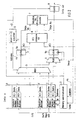
- the output unit shown in FIG. 2 has one Buffer memory 1, a memory management unit 2, two Multiplexers 3 and 4, two buffers 5a and 5b, two comparators 6 and 7, another buffer 8 and a counter 9 on.
- VCI The second type, identifies the Belonging a cell to a certain virtual Connection.
- Data, 1 instead of the rest of the cell, Data, 1 also the address under which this is saved Rest is stored in another memory.
- the buffer memory 1 is divided into three parts, namely a shift register-like part, Shift Register, with memory locations 1 to d and one after Kind of a FIFO memory operated part, FIFO, the again from two parts with memory locations d + 1 to r and r + 1 to p is composed. At least on that Storage locations 1 to r must be individually such can be accessed so that their contents are read can or that new content is written into it can be.
- the dimensioning of the buffer memory i.e. the vote the numerical values for d, r and p must be specific Use case. This must be taken into account above all the permissible error rate, the minimum and maximum runtime of a cell since the first Branch point, the number of simultaneously over one Connections approved for an output unit Connection allowed minimum and maximum number of Cells per unit of time and their permitted Fluctuation range.
- d 10
- Point-to-multipoint connections initially the Main switch 10, then the copy switch 20 and then run through the main switching matrix 10 again, are the above values with a factor of 2 ...
- Cells arriving at the input of the output unit are first examined to see if it is at the exit cells to be output or those that are in the Output unit ends. On the one hand, these are empty cells, on the other hand, the control signals for the Output unit (or one usually associated with it) Input unit that cannot be reached otherwise) contain.
- the cells to be output are in the Buffer memory 1 entered such that they first in that operated in the manner of a FIFO memory Part down to the lowest free space "fall through”. Whenever there is a cell at the exit is output, all cells move in the buffer memory one space down. Is the last Memory space of the FIFO memory, d + 1, is used, then the cell it contains in the first memory location of the shift register, d.
- the memory management unit 2 is only very much in FIG. 2 shown schematically.
- the first task is the normal operation of the To ensure buffer memory 1. This is done by Creation of addresses, address, write commands, W, and Read commands, R. Also, in Fig. 2 is not shown, information about the presence or Absence of a cell to be enrolled required.
- the memory management unit 2 also has the task of the content of the addressed by the counter 9 Storage space, address, against the content of the To exchange buffer memory 5b if a command to do this Swap is given.
- the multiplexer 3 can optionally on the content one of the memory locations 2 to r of the buffer memory 1 accessed and passed on to the buffer 5a will.
- the storage location is selected by the Counter 9, Address.
- swap is by means of of the multiplexer 4 the content of the buffer memory 5a in the buffer 5b taken over. That by means of the same Command, swap, written in the buffer memory 5b and reading from it is nothing unusual and can be carried out by a specialist using customary measures be taken into account.
- the comparator 6 marks the second type, VCI, compared to those two cells that just stored in the buffers 5a and 5b are. Only if the two brands of the second kind are identical, i.e. if the two cells of the same connection the following comparator is activated.
- the comparator 7 compares the brands of the first kind, Sequence Number, the two in the buffers 5a and 5b contained cells. If comparator 6 shows that both cells belong to the same connection and will found that the contained in the buffer 5a Cell is older than that in buffer 5b a command, swap, is issued by which the older cell in the buffer 5b and the younger cell in its place in the buffer memory 1 be taken over. As a result, the two Cells swapped.
- the content of the Buffer 5b which in the previous cycle as the oldest cell belonging to a particular connection was recognized, is transferred to the buffer 8 and is available for output at its exit, Cells out Available.
- the content of the Storage location 1 of the buffer memory 1 via the Multiplexer 4 taken over in the buffer memory 5b. Then the storage locations 2 down to r on older cells (brands of the first kind) Connection (brands of the second kind) examined.
- the representation of the output unit selected in FIG. 2 shows above all how the output unit works.
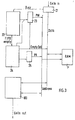
- the construction and management of the buffer memory with a part operated in the manner of a FIFO memory and a part operated like a shift register clearly in the illustration chosen in FIG Expression.
- the distribution of clocks, including the Write and read commands are not shown here.
- the buffer memory is a read-write memory (RAM), 1 ', realized.
- the incoming cells are over an input memory 21 on a data bus, data, given on which the read-write memory 1 ' connected.
- a registration control 22 is from Input memory 21 activated, busy if one cell to be registered. Via the registered counter 23 becomes an address PW via an address bus, Address read-write memory 1 'and the cell in registered this. Then the Registration counter 23 from the registration controller 22 incremented.
- a readout control 24 outputs a Read counter 25 the address, PR, to which the Storage space 1 corresponds. After each issue of a Cell is the readout counter 25 from the readout control 24 from incremented.
- the difference between the content PW of the enrollment counter 23 and the content PR of the Readout counter 25 must always be at least equal to d. This is monitored by the registration control 22 and if necessary, FIFO empty, to the readout controller 24 reported, which is then sent to the data bus, data, an empty cell, Empty Cell, creates and registered in the by the Registered counter 23 causes the specified storage space and then increment the enrollment counter 23.
- the rest of the output unit is here by one Access, comparator and output unit 100 shown.
- the part of the Buffer memory does not necessarily have to form the end of it. He can also be at the beginning or in the middle of the buffer memory lie.
- the dimensions, and thus the storage requirements, depend not only of the structure of the exchange and the predetermined permissible error rates, but also from the mode of operation.
- Typical examples of point-to-multipoint connections are conference calls and sound or Television broadcasting.
- the associated cells represent a continuous signal stream. she arise at the transmitter at constant intervals and are not only in the correct order for the recipient, but also back to the original constant Distances needed.
- the Group 42 and Group 43 output units may or may not exist for themselves. Also if already in one of groups 42 or 43 the original episode has been restored, it may make sense in the next output unit, in group 41 at the latest, again the same the result to use distinctive brands. Therefore, too group 33 and group 32 input units either be there for yourself or not. Group 33 must not be present if group 42 is not present; group 32 must not exist if group 43 does not exist.
Landscapes
- Engineering & Computer Science (AREA)
- Computer Networks & Wireless Communication (AREA)
- Signal Processing (AREA)
- Data Exchanges In Wide-Area Networks (AREA)
- Use Of Switch Circuits For Exchanges And Methods Of Control Of Multiplex Exchanges (AREA)
Abstract
Description
Die Erfindung betrifft eine kopierfähige
ATM- Vermittlungsstelle zur Vermittlung von ATM-Zellen, nach
dem Oberbegriff von Anspruch 1.The invention relates to a copyable
ATM switching center for switching ATM cells, according to
the preamble of
Eine solche ATM-Vermittlungsstelle ist bekannt aus WO 87/00372. Weiter ist auch bekannt eine Vermittlungsstelle mit einer Aufeinanderfolge aus Kopierkoppelfeld, Verteilkoppelfeld und Zielkoppelfeld.Such an ATM switching center is known from WO 87/00372. Is further known a switching center with a sequence of copy switching matrix, Distribution switching matrix and target switching matrix.
Realer Betrieb ist eine Mischung aus Punkt-zu-Punkt-Verbindungen, Punkt-zu-Mehrpunkt-Verbindungen mit wenigen Verzweigungen und Punkt-zu-Mehrpunkt-Verbindungen mit vielen Verzweigungen. Der Gesamtverkehr und die einzelnen Anteile ändern sich laufend. Die bekannten Strukturen sind jeweils nur einseitig auf eine bestimmte Verkehrsart optimiert.Real operation is a mix of both Point-to-point connections, Point-to-multipoint connections with few branches and point-to-multipoint connections with many Ramifications. The total traffic and the individual Shares change continuously. The well-known structures are only one-sided for a certain type of traffic optimized.
Der Erfindung liegt die Aufgabe zugrunde, eine kopierfähige ATM-Vermittlungsstelle anzugeben, die verschiedenartigen, auch wechselnden Verkehrsarten gleichermaßen angepaßt ist. The invention has for its object a to specify copyable ATM switch that various types of traffic, including those that change is equally adapted.
Die Aufgabe wird gelöst durch eine ATM-Vermittlungsstelle nach der Lehre des Hauptanspruchs. Vorteilhafte Ausgestaltungen der Erfindung sind den Unteransprüchen zu entnehmen.The task is solved by an ATM switching center according to the teaching of the main claim. Beneficial Embodiments of the invention are in the subclaims remove.
Die Lösung baut auf dem Grundgedanken auf, die Koppelelemente eines Koppelfelds, das für Punkt-zu-Punkt-verbindungen optimiert ist, zusätzlich mit der Möglichkeit zu versehen, einige wenige Eingangssignale für beliebig viele Ausgänge zu kopieren, womit insgesamt für wenige Eingangssignale eine sehr hohe Kopienzahl erreichbar ist. Dieses Hauptkoppelfeld wird ergänzt durch ein Kopierkoppelfeld, das ausschließlich der Erstellung einer jeweils begrenzten Anzahl von Kopien für eine große Zahl von Eingangssignalen dient, die dann im Hauptkoppelfeld als Punkt-zu-Punkt-verbindungen vermittelt werden.The solution is based on the basic idea that Coupling elements of a switching matrix that for Point-to-point connections is optimized, in addition with the possibility to provide a few Copy input signals for any number of outputs, making a very high overall for a few input signals Number of copies can be reached. This main switching matrix will supplemented by a copy switching matrix that only making a limited number of copies serves for a large number of input signals which then in the main switching matrix as point-to-point connections mediated.
Die Verwendung eines separaten Kopierkoppelfeldes ist, im Zusammenhang mit einem einstufigen Hauptkoppelfeld, bereits bekannt aus IEEE INFOCOM 88, März 1988, New Orleans, US, Seiten 29-34, K. Eng et al.: "Multicast and Broadcast Services in a Knockout Packet Switch".The use of a separate copy switching matrix is related to a single-stage switching matrix, already known from IEEE INFOCOM 88, March 1988, New Orleans, US, pp. 29-34, K. Eng et al .: "Multicast and Broadcast Services in a Knockout Packet Switch ".
Die Verwendung von Ausgangseinheiten, in denen nach der ursprünglichen Reihenfolge sortiert wird, ist schon in der nicht vorveröffentlichten EP-Al-0 435 046 beschrieben.The use of output units in which after the original Order is sorted is already in the unpublished EP-Al-0 435 046 described.
Punkt-zu-Punkt-Verbindungen werden im Hauptkoppelfeld als "verbindungslose Verbindungen" mittels Selbststeuerung der Koppelelemente betrieben. Es wird dafür gesorgt, daß diese Verbindungen nach außen als virtuelle Verbindungen wirken. Punkt-zu-Mehrpunkt-Verbindungen werden auch im Hauptkoppelfeld als virtuelle Verbindungen (verbindungsorientiert) mittels Verbindungstabellen betrieben.Point-to-point connections are in the main switching matrix as "Connectionless connections" using self-control the coupling elements operated. It is ensured that these connections to the outside as virtual connections Act. Point-to-multipoint connections are also in the Main switching matrix as virtual connections (connection-oriented) using connection tables operated.
Als "verbindungslose Verbindungen" werden solche Verbindungen angesehen, bei denen die einzelnen Zellen einer Verbindung nicht denselben Weg gehen, sondern auf alle möglichen Wege aufgeteilt werden. Dadurch tritt eine recht gleichmäßige Belastung ein; auf Verkehrsmessungen kann verzichtet werden, die dafür sonst erforderlichen Vorrichtungen sind nicht erforderlich. Es besteht aber die Notwendigkeit, auf die richtige Reihenfolge der Zellen zu achten, weil hier Überholvorgänge nicht ausgeschlossen sind.Such are called "connectionless connections" Connections viewed in which the individual cells of a connection do not go the same way, but on all possible ways can be divided. This causes a fairly even load; on traffic measurements can be dispensed with, the otherwise necessary for this Devices are not required. But there is the need to be in the correct order of Cells to watch out for, because overtaking here is not excluded are.
"Verbindungslose Verbindungen" setzen Koppelelemente voraus, die durch eine in der Wegeinformation enthaltene Adresse direkt gesteuert werden. Die Erstellung von Kopien für Punkt-zu-Mehrpunkt-Verbindungen ist mittels einer solchen Adressierung nur sehr schwer möglich. Beispiele für solche Koppelelemente sind bekannt."Connectionless connections" set coupling elements ahead by one contained in the route information Address can be controlled directly. The creation of Copies for point-to-multipoint connections is by means of such addressing is very difficult. Examples of such coupling elements are known.
Bekannt sind auch Koppelelemente, die durch indirekte Adressierung gesteuert werden. Als Wegeinformation kommen hierbei Verbindungsnummern in Frage, die in jedem Koppelelement anhand von Verbindungstabellen ausgewertet werden. Ist eine Verbindungsnummer in der Verbindungstabelle eines Koppelelements für mehrere Ausgänge enthalten, so wird an jeden dieser Ausgänge eine Kopie einer Zelle mit dieser Verbindungsnummer ausgegeben.Coupling elements are also known, through indirect Addressing can be controlled. Come as route information connection numbers in question in each Coupling element evaluated using connection tables will. Is a connection number in the Connection table of a coupling element for several Contains outputs, so there is one at each of these outputs Copy of a cell with this connection number spent.
Gerade bei Punkt-zu-Mehrpunkt-Verbindungen kann es durch stetigen Wechsel der Teilnehmer zu einer ungleichmäßigen Belastung des Hauptkoppelfelds kommen. Da das Hauptkoppelfeld aber primär für "verbindungslose Verbindungen" ausgelegt ist, muß es an seinen Ausgängen Einrichtungen aufweisen, die der Sicherung der richtigen Reihenfolge der Zellen nach etwaigen Überholvorgängen dienen. Es ist deshalb problemlos möglich, bestehende virtuelle Verbindungen umzusortieren. Dabei kurzfristig auftretende Überholvorgänge werden wie bei den "verbindungslosen Verbindungen" korrigiert. Especially with point-to-multipoint connections, it can be done by steady change of participants to an uneven Load on the main switching matrix. Since that Main switching matrix but primarily for "connectionless Connections "is designed at its outputs Have facilities that ensure the correct Sequence of cells after any overtaking to serve. It is therefore possible to easily create existing ones to sort virtual connections. At short notice Overtaking that occurs is the same as for the Corrected "connectionless connections".
Die Verwendung von Verbindungsnummern für Punkt-zu-Mehrpunkt-Verbindungen im Hauptkoppelfeld zwingt zu besonderen Vorsichtsmaßnahmen, wenn eine Verbindungsnummer mehrfach verwendet werden soll. Auf jeden Fall ist die Gesamtzahl der im Hauptkoppelfeld möglichen Punkt-zu-Mehrpunkt-Verbindungen begrenzt. Dafür könnten aber an einer solchen Punkt-zu-Mehrpunkt-Verbindung grundsätzlich alle das Hauptkoppelfeld verlassenden Leitungen beteiligt sein.The use of connection numbers for Forces point-to-multipoint connections in the main switching matrix on special precautions if a Connection number should be used several times. On in any case is the total number in the main switching matrix possible point-to-multipoint connections are limited. Therefore but could on such Point-to-multipoint connection basically all of that Leaving the main switching network.
Um mehr Punkt-zu-Mehrpunkt-Verbindungen gleichzeitig zulassen zu können, ist ein separates Kopierkoppelfeld vorgesehen. Von jedem Eingang der Vermittlungsstelle muß ein Eingang des Kopierkoppelfelds erreichbar sein. Es ist nicht zwingend, daß jeder Eingang des Kopierkoppelfelds von jedem Eingang der Vermittlungsstelle erreichbar ist. Bevorzugt wird ein Zugang über das Hauptkoppelfeld, wobei jeder Eingang der Vermittlungsstelle mit einem Eingang des Hauptkoppelfelds und jeder Eingang des Kopierkoppelfelds mit einem Ausgang des Hauptkoppelfelds verbunden ist.To make more point-to-multipoint connections at the same time To be able to allow is a separate copy switching matrix intended. From every entrance to the exchange an input of the copy switching matrix can be reached. It is not necessarily that every input of the copy switching matrix can be reached from any entrance to the exchange. Access via the main switching matrix is preferred, whereby each entrance to the exchange with one entrance of the main switching matrix and each input of the Copy switching matrix with an output of the main switching matrix connected is.
Das Kopierkoppelfeld hat ausschließlich die Aufgabe, die jeweils erforderliche Zahl von Kopien zu erstellen. Die Vermittlung dieser Kopien erfolgt im Hauptkoppelfeld jeweils nach Art einer Punkt-zu-Punkt-Verbindung. Nicht jeder Ausgang des Kopierkoppelnetzes muß von jedem seiner Eingänge erreichbar sein. Die Stufenzahl hängt nur von der Kopierfähigkeit der einzelnen Koppelelemente (d.h., von der Zahl der Ausgänge der Koppelelemente) und von der maximal geforderten Kopienzahl ab. In der Regel reicht ein Kopierkoppelfeld mit wenigen Stufen aus (z.B. zwei- bis dreistufig bei 16X16-Koppelementen). Jede Verbindungsnummer kann hier mehrfach verwendet werden; die Zahl der gleichzeitig möglichen Verbindungen im Kopierkoppelfeld ist deshalb insofern kaum Beschränkungen unterworfen.The copy switching matrix has only the task that make the required number of copies. The These copies are mediated in the main switching matrix each in the manner of a point-to-point connection. Not each output of the copy switching network must be from each of its Inputs can be reached. The number of stages only depends on the copying ability of the individual coupling elements (i.e., on the number of outputs of the coupling elements) and on the the maximum number of copies required. Usually enough a copy switching matrix with a few steps (e.g. two to three-stage with 16X16 coupling elements). Each The connection number can be used several times here; the number of connections possible at the same time Copy switching matrix is therefore hardly any restrictions subject.
Eine so aufgebaute Vermittlungsstelle kann jede Art von Verkehr bearbeiten. Lokale interne Blockierungen können entweder nicht auftreten (Punkt-zu-Punkt-Verbindungen) oder ohne Störungen jederzeit aufgelöst werden (Punkt-zu-Mehrpunkt-Verbindungen). Auch zwischen den beiden Möglichkeiten der Punkt-zu-Mehrpunkt-Verbindungen kann jederzeit ohne Störungen umgeschaltet werden, um die Auslastung an die aktuelle Situation anzupassen. Damit kann insgesamt eine sehr gleichmäßige Auslastung des Hauptkoppelfelds erreicht werden. Eine teilweise Blockierung durch voll ausgelastete Abnehmerleitungen oder eine insgesamt zu hohe Belastung kann aber nicht verhindert werden.A switching center constructed in this way can be of any kind Edit traffic. Local internal blockages can either do not occur (point-to-point connections) or be resolved at any time without interference (Point-to-multipoint connections). Even between the two possibilities of point-to-multipoint connections can be switched at any time without interference to the Adapt utilization to the current situation. In order to can be a very even utilization of the Main switching matrix can be reached. A partial one Blocking due to fully utilized customer lines or a load that is too high overall cannot be prevented.
Als Nachteil kann angesehen werden, daß im Hauptkoppelfeld besondere Koppelelemente erforderlich sind, die mit zwei verschiedenen Adressierungsmöglichkeiten arbeiten können. Diese Koppelelemente können aber auch dort verwendet werden, wo eine der beiden Adressierungsmöglichkeiten gar nicht gebraucht wird, beispielsweise im Kopierkoppelfeld. Derartige Koppelelemente können deshalb als Universalkoppelelemente verwendet werden.A disadvantage can be seen that in Main switching matrix special coupling elements required are that with two different Addressing options can work. This Coupling elements can also be used where not one of the two addressing options is needed, for example in the copy switching matrix. Such coupling elements can therefore as Universal coupling elements are used.
Im folgenden wird die Erfindung anhand eines Ausführungsbeispiels unter Zuhilfenahme der beiliegenden Zeichnungen weiter erläutert.
- Fig. 1
- zeigt ein bevorzugtes Ausführungsbeispiel einer erfindungsgemäßen ATM-Vermittlungsstelle.
- Fig. 2
- zeigt ein Blockschaltbild einer Ausgangseinheit für die erfindungsgemäße Vermittlungsstelle.
- Fig. 3
- zeigt eine Realisierungsmöglichkeit für den in der Ausgangseinheit nach Fig. 2 enthaltenen Pufferspeicher.
- Fig. 1
- shows a preferred embodiment of an ATM switching center according to the invention.
- Fig. 2
- shows a block diagram of an output unit for the switching center according to the invention.
- Fig. 3
- shows a possible implementation for the buffer memory contained in the output unit of FIG. 2.
Die ATM-Vermittlungsstelle nach Fig. 1 weist Eingänge I1,
I2, ..., Ii, Ausgänge O1, O2, ..., Ol, ein
Hauptkoppelfeld 10, ein Kopierkoppelfeld 20, drei Gruppen
von Eingangseinheiten 31, 32 und 33 und drei Gruppen von
Ausgangseinheiten 41, 42 und 43 auf. Die Gruppe 31
enthält i Eingangseinheiten 311, 312, ..., 31i; die
Gruppe 32 enthält j Eingangseinheiten 321, 322, ..., 32j;
die Gruppe 33 enthält k Eingangseinheiten 331, 332, ...,
33k; die Gruppe 41 enthält l Ausgangseinheiten 411, 412,
..., 41l; die Gruppe 42 enthält k Ausgangseinheiten 421,
422, ..., 42k; die Gruppe 43 enthält j Ausgangseinheiten
431, 432, ..., 43j.1 has inputs I1,
I2, ..., Ii, outputs O1, O2, ..., Ol, on
Jeder der Eingänge I1, I2, ..., Ii der Vermittlungsstelle
ist mit dem Eingang einer der Eingangseinheiten 311, 312,
..., 31i der Gruppe 31 verbunden, deren Ausgänge jeweils
mit einem Eingang des Hauptkoppelfelds 10 verbunden sind.
Jeder der Ausgänge O1, O2, ..., Ol der Vermittlungsstelle
ist mit dem Ausgang einer der Ausgangseinheiten 411, 412,
..., 41l der Gruppe 41 verbunden, deren Eingänge jeweils
mit einem Ausgang des Hauptkoppelfelds 10 verbunden sind.Each of the inputs I1, I2, ..., Ii of the exchange
is connected to the input of one of the
Die Eingänge der Ausgangseinheiten 421, 422, ..., 42k der
Gruppe 42 sind mit weiteren Ausgängen des
Hauptkoppelfelds 10 verbunden. Die Ausgänge der
Ausgangseinheiten 421, 422, ..., 42k der Gruppe 42 sind
jeweils mit dem Eingang einer der Eingangseinheiten 331,
332, ..., 33k der Gruppe 33 verbunden, deren Ausgänge mit
Eingängen des Kopierkoppelfelds 20 verbunden sind.The inputs of the
Die Eingänge der Ausgangseinheiten 431, 432, ..., 43j der
Gruppe 43 sind mit je einem Ausgang des Kopierkoppelfelds
20 verbunden. Die Ausgänge der Ausgangseinheiten 431,
432, ..., 43j der Gruppe 43 sind jeweils mit dem Eingang
einer der Eingangseinheiten 321, 322, ..., 32j der Gruppe
32 verbunden, deren Ausgänge mit weiteren Eingängen des
Hauptkoppelfelds 10 verbunden sind.The inputs of the
Für die vorliegende Erfindung ist es ohne Bedeutung, ob die Eingänge I1, I2, ..., Ii und die Ausgänge O1, O2, ..., Ol auch mit Endteilnehmern, Nebenstellenanlagen, Vorfeldeinrichtungen oder nur mit anderen Vermittlungsstellen verbunden sind. In der Regel wird die Zahl der Eingänge, i, gleich der Zahl der Ausgänge, l, sein, d.h. i = l.For the present invention, it is irrelevant whether inputs I1, I2, ..., Ii and outputs O1, O2, ..., oil also with end users, private branch exchanges, Apron facilities or only with others Agencies are connected. As a rule, the Number of inputs, i, equal to the number of outputs, l, be, i.e. i = l.
Das Hauptkoppelfeld 10 enthält eine Vielzahl von in
mehreren Stufen angeordneten Koppelelementen. Es ist so
aufgebaut, daß Verbindungen zwischen jedem Eingang und
jedem Ausgang möglich sind. Beispiele derartiger
Koppelfelder sind jedem Fachmann geläufig.The
Die einzelnen Koppelelemente sind so aufgebaut, daß sie durch eine im Zellkopf enthaltene Information umschaltbar sind zwischen einer ersten Adressierungsart, bei der die Zelle aufgrund einer mittels eines von außen nicht beeinflußbaren Algorithmus ausgewerteten Wegeinformation weitergeleitet wird, und einer zweiten Adressierungsart, bei der die Zelle aufgrund der mit Hilfe einer Verbindungstabelle ausgewerteten Wegeinformation weitergeleitet wird. Dabei ist vorgesehen, daß bei der zweiten Adressierungsart eine Zelle auch kopiert und auf mehreren Wegen weitergeleitet werden kann.The individual coupling elements are constructed so that they switchable by information contained in the cell header are between a first type of addressing, in which the Cell due to one by means of an outside influenceable algorithm evaluated route information is forwarded, and a second type of addressing, where the cell due to the help of a Connection table evaluated route information is forwarded. It is provided that the second type of addressing a cell is also copied and opened can be forwarded in several ways.
ATM-Koppelelemente, die mit Adressierung mittels eines von außen nicht beeinflußbaren Algorithmus arbeiten, sind dem Fachmann ebenso bekannt wie solche, die mit Adressierung mittels Verbindungstabelle arbeiten.ATM coupling elements with addressing by means of a algorithm that cannot be influenced from the outside known to those skilled in the art as well as those that Work addressing using the connection table.
Als Algorithmus kommt beispielsweise eine
Zuordnungsvorschrift in Frage, wie sie aus "SYSTEM 12,
Digital-Koppelnetz", Elektrisches Nachrichtenwesen, Band
56, Nr. 2/3, 1981, Seiten 148-160 für
Zeitmultiplexvermittlungsanlagen bekannt ist. Dort
besteht die Möglichkeit, eine ganz bestimmte, durch die
Wegeinformation direkt vorgegebene Ausgangsleitung zu
adressieren. Es besteht auch die Möglichkeit, durch die
Wegeinformation eine beliebige Ausgangsleitung anwählen
zu lassen. Die dort gegebene Möglichkeit, innerhalb einer
Ausgangsleitung auch noch einen bestimmten Kanal
auszuwählen, ist bei ATM weder möglich noch erforderlich.
Sinnvoll ist aber die Möglichkeit, durch die
Wegeinformation eine beliebige Ausgangsleitung aus einer
vorgegebenen Gruppe von Ausgangsleitungen auszuwählen.
Bei der Auswahl einer beliebigen Ausgangsleitung kann
beispielsweise die augenblickliche Auslastung
herangezogen werden. Es ist auch möglich, durch die
Wegeinformation eine im Koppelelement enthaltene
Einrichtung zu adressieren, beispielsweise, um die für
die zweite Adressierungsart erforderliche
Verbindungstabelle zu verändern.An algorithm comes for example
Allocation rule in question, as they from "
Die für die zweite Adressierungsart erforderliche Verbindungstabelle kann ein RAM mit M Adressbits und N Datenbits sein. Die Adressbits werden durch die für dieses Koppelelement gültigen Bits der Wegeinformation gebildet, die Datenbits geben diejenige Ausgangsleitung an, auf die auszugeben ist. Sind mehrere Datenbits gleichzeitig gesetzt, so wird die Zelle auf mehreren Ausgangsleitungen ausgegeben, wodurch auf einfache Weise ein Kopieren von Zellen erreicht ist. Statt eines einzigen RAM kann auch jedem Ausgang zugeordnet ein RAM mit M Adressbits und einem Datenbit vorgesehen sein, beispielsweise ein 128 x 1 - RAM für M = 7.The one required for the second type of addressing A RAM with M address bits and N Data bits. The address bits are identified by the for this coupling element valid bits of route information formed, the data bits give that output line to be spent on. Are multiple data bits set at the same time, the cell will be on several Output lines output, making it easy copying of cells is achieved. Instead of one A single RAM can also be assigned to each output be provided with M address bits and one data bit, for example a 128 x 1 RAM for M = 7.
Die Koppelelemente müssen so aufgebaut sein, daß sie auf
zwei unterschiedliche Arten arbeiten können. Hierfür ist
grundsätzlich ein Aufbau geeignet, wie er anhand der
Figuren 3 und 5 der DE-A1 37 42 939.6 beschrieben ist.
Die dort beschriebenen Teil-Koppelelemente 22 und 24
müssen hier ersetzt werden durch ein Teil-Koppelelement
für die erste Adressierungsart und ein Teil-Koppelelement
für die zweite Adressierungsart.The coupling elements must be designed so that they are on
can work in two different ways. For this is
basically a structure suitable, as it is based on the
Figures 3 and 5 of DE-A1 37 42 939.6 is described.
The
Das Hauptkoppelfeld 10 ist für
Punkt-zu-Punkt-Verbindungen optimiert. Hierzu ist es so
aufgebaut und wird so betrieben, daß in der ersten Hälfte
jede Zelle einen beliebigen Weg nimmt, so daß damit der
Verkehr gleichmäßig aufgeteilt wird. In der zweiten
Hälfte wird dann jede Zelle gezielt zum gewünschten
Ausgang geleitet. Jedes Koppelelement der mittleren Stufe
muß deshalb von jedem Eingang des Hauptkoppelfelds aus
erreichbar sein und auch jeden Ausgang des
Hauptkoppelfelds erreichen können.The
Bevorzugt wird als Hauptkoppelfeld ein Umkehrkoppelfeld.
Jedes Koppelelement der ersten Stufe ist dabei
gleichzeitig Koppelelement der letzten Stufe. Ein Teil
seiner Eingänge ist mit Eingängen des Hauptkoppelfelds,
ein anderer Teil seiner Eingänge ist mit Ausgängen von
Koppelelementen der vorletzten Koppelstufe verbunden. Ein
Teil seiner Ausgänge ist mit Eingängen von
Koppelelementen der zweiten Koppelstufe verbunden, ein
anderer Teil seiner Ausgänge ist mit Ausgängen des
Hauptkoppelfelds verbunden. Jedes Koppelelement der
zweiten Stufe ist gleichzeitig Koppelelement der
vorletzten Stufe, usw. Die Stufenzahl ist ungerade.
Solche Umkehrkoppelfelder sind von der
Zeitmultiplextechnik her bekannt, beispielsweise aus dem
genannten Artikel "SYSTEM 12, Digital-Koppelnetz". Sie
haben den Vorteil, daß die mittleren Stufen nicht
zwingend für jede Verbindung benutzt werden müssen.A reversing switching matrix is preferred as the main switching matrix.
Each coupling element of the first stage is included
at the same time coupling element of the last stage. A part
its inputs are with inputs of the main switching matrix,
another part of its inputs is with outputs from
Coupling elements of the penultimate coupling stage connected. A
Part of its outputs is with inputs from
Coupling elements of the second coupling stage connected
other part of its outputs is with outputs of the
Main switching matrix connected. Each coupling element of the
second stage is also the coupling element of the
penultimate step, etc. The number of steps is odd.
Such switching matrixes are from
Time division multiplex technology known, for example from the
mentioned article "
Das Kopierkoppelfeld 20 kann aus denselben
Koppelelementen aufgebaut sein, wobei hier aber nur eine
der Adressierungsarten benutzt wird. Im Gegensatz zum
Hauptkoppelfeld 10 muß hier aber nicht jeder Ausgang von
jedem Eingang erreichbar sein. Es genügt, wenn von jedem
Eingang aus eine vorgegebene Zahl von Ausgängen
erreichbar ist. Es muß auch nicht zwingend von jedem
Eingang aus dieselbe Zahl von Ausgängen erreichbar sein.
Das Kopierkoppelfeld 20 kann deshalb aus einem Teil
bestehen, in dem von jedem Eingang aus 128 Ausgänge
erreichbar sind und aus einem anderen Teil, in dem von
jedem Eingang aus 32 Ausgänge erreichbar sind. Es muß
natürlich berücksichtigt werden, daß die gesamte
Verkehrsbelastung vom Eingang des Kopierkoppelfelds zu
dessen Ausgang hin in Abhängigkeit vom durchschnittlichen
Kopierfaktor ansteigt.The copy switching matrix 20 can be made of the same
Coupling elements can be constructed, but here only one
the types of addressing is used. In contrast to
Auch wenn wegen der Erhöhung des Verkehrs durch das
Kopieren die Zahl der Ausgangseinheiten in der Gruppe 42,
die gleich der Zahl der Eingangseinheiten in der Gruppe
33 ist, kleiner ist als die Zahl der Ausgangseinheiten in
der Gruppe 43, die gleich der Zahl der Eingangseinheiten
in der Gruppe 32 ist, so ist es doch möglich, jede
Eingangseinheit der Gruppe 32 fest einer Ausgangseinheit
der Gruppe 42 und jede Ausgangseinheit der Gruppe 43 fest
einer Eingangseinheit der Gruppe 33 zuzuordnen. Statt
einer Zuordnung von Einheiten der Gruppe 43 zu Einheiten
der Gruppe 33 ist auch eine Zusammenfassung der
Ausgangseinheiten der Gruppe 43 mit den entsprechenden
Eingangseinheiten der Gruppe 32 und eine Zusammenfassung
der Ausgangseinheiten der Gruppe 42 mit den
entsprechenden Eingangseinheiten der Gruppe 33 möglich.
Die Zuordnung oder Zusammenfassung sollte zumindest den
Austausch von Steuerdaten zulassen.Even if due to the increase in traffic through the
Copy the number of output units in
Zusammen mit der Ausbildung des Hauptkoppelfelds 10 als
Umkehrkoppelfeld ist damit die Möglichkeit geschaffen,
daß sämtliche Teile der Vermittlungsstelle (Eingangs- und
Ausgangseinheiten, Koppelelemente) über die normalen
Verbindungswege auf einfache Weise Steuerdaten
austauschen können. Über weitere Ein- und Ausgänge des
Hauptkoppelfeldes 10 können verschiedene
Hilfseinrichtungen angeschlossen sein, die in gleicher
Weise mit allen anderen Teilen der Vermittlungsstelle
Steuerdaten austauschen können. Steuerung, Diagnose und
Wertung sind aber nicht Gegenstand der vorliegenden
Erfindung.Together with the formation of the
Zu den Eingangs- und Ausgangseinheiten ist zunächst zu bemerken, daß alle Vermittlungsstellen irgendwelche Arten von Eingangs- und Ausgangseinheiten aufweisen. Hier soll nur das beschrieben werden, was für die Erfindung spezifisch ist. To start with the input and output units notice that all exchanges of any kind of input and output units. Here is supposed to only what is described for the invention is specific.
Jede Eingangseinheit hat zunächst die Aufgabe, jeder zu
vermittelnden Zelle eine Wegeinformation beizufügen.
Hierzu wird auf die Seiten 6 bis 9 eines Artikels von W.
Schmidt in "Der Fernmelde=Ingenieur", Heft 9, September
1987, verwiesen. Dort wird der grundsätzliche
Vermittlungsablauf beschrieben. Im Zellkopf einer jeden
Zelle muß zwangsläufig eine verbindungsindividuelle
Kennzeichnung enthalten sein. Aus dieser wird in der
Eingangseinheit aufgrund einer Tabelle eine
Wegeinformation für das nachfolgende Koppelnetz ermittelt
und der Zelle beigefügt. Dabei braucht zwischen den
beiden Adressierungsarten überhaupt nicht unterschieden
zu werden, da das Datenformat zwangsläufig gleich sein
muß.Each input unit first has the task of everyone
to provide route information to the mediating cell.
For this purpose, pages 6 to 9 of an article by W.
Schmidt in "Der Fernmelde = Ingenieur",
In dem genannten Artikel sind auf Seite 7, vorletzter
Abschnitt, auch "Systeme, die mit Zeitmarken arbeiten"
genannt. Bei diesen muß "die Ankunftszeit eines Pakets
ermittelt und der Paketinformation am Eingang des Knotens
hinzugefügt werden". Wenn diese Zeitmarken ausreichend
fein auflösen, dann können sie auch verwendet werden, um
die Reihenfolge der Zellen zu kennzeichnen. Auch wenn an
sich keine Zeitmarken gebraucht werden, kann in gleicher
Weise verfahren werden, um die Reihenfolge zu
kennzeichnen. Es können aber auch in jeder
Eingangseinheit unabhängige Modulo-N-Zähler verwendet
werden, um diese Marken, im folgenden auch als Marken
erster Art bezeichnet, zu vergeben. Da die richtige
Reihenfolge nur zwischen den Zellen jeder einzelnen
Verbindung gewährleistet sein muß, können die
Verbindungsnummern, sofern solche vorhanden sind, als
Ausscheidungskriterium mit verwendet werden, sie werden
im folgenden als Marken zweiter Art bezeichnet. Die
Marken erster Art können sowohl für die Zellen jeder
einzelnen Verbindung getrennt als auch für die Zellen
aller über eine Eingangseinheit geführten Verbindungen
gemeinsam vergeben werden.In the article mentioned are on
Insoweit, als unter Eingangseinheit nur das angesehen wird, was erfindungsspezifisch zu einer bekannten ATM-Vermittlungsstelle hinzukommt, wird nur dann eine Eingangseinheit benötigt, wenn die von außen kommenden Zellen nicht bereits eine die Reihenfolge kennzeichnende Marke enthält oder wenn diese nicht ohne weiteres verwertbar ist.Insofar as viewed only under the input unit becomes what is known to be specific to the invention ATM switch will only be added Input unit needed if the coming from outside Cells do not already have a sequence Brand contains or if this is not readily is usable.
Anhand der Fig. 2 und 3 wird ein Ausführungsbeispiel für eine Ausgangseinheit beschrieben. Alle Ausgangseinheiten sind grundsätzlich untereinander gleich. Sie unterscheiden sich im wesentlichen durch die vorgegebene Verzögerungszeit.2 and 3, an embodiment for described an output unit. All output units are basically the same among each other. she differ essentially by the given Delay Time.
Der Grundgedanke dieses Ausführungsbeispiels liegt darin, jede Zelle am Ausgang solange anzuhalten, bis sichergestellt ist, daß keine ältere Zelle mehr unterwegs zwischengespeichert sein kann. Vor der Weitergabe der Zelle wird geprüft, ob unter den später am Ausgang angekommenen Zellen noch eine Zelle ist, die vorher auszugeben ist.The basic idea of this embodiment is stop each cell at the exit until it is ensured that no older cell is on the move can be cached. Before sharing the The cell is checked to see if it is later at the exit arrived cells is still a cell that was previously is to be spent.
Dies wird vorzugsweise dadurch realisiert, daß ausgangsseitig ein Pufferspeicher vorhanden ist, der mindestens teilweise schieberegisterartig betrieben wird und dadurch eine vorgegebene Verzögerung bewirkt. Vor Ausgabe einer Zelle wird mindestens der schieberegisterartig betriebene Teil des Pufferspeichers daraufhin untersucht, ob eine später eingeschriebene Zelle früher auszugeben ist. Wenn ja, werden die beiden Zellen vertauscht. This is preferably realized in that on the output side there is a buffer memory which is operated at least partially like a shift register and thereby causes a predetermined delay. In front The output of a cell will be at least the part of the buffer memory operated in the form of a shift register then examined whether a later enrolled Cell to be output earlier. If so, the two will Cells swapped.
In diesem Ausführungsbeispiel einer Ausgangseinheit wird ein Datenstrom angenommen, der auf Zellbreite parallelisiert ist, bei dem also alle Bits einer Zelle gleichzeitig auf parallelen Leitungen weitergegeben werden. Dies ist in der Regel weder gegeben noch besonders vorteilhaft. Einerseits ist es aber immer möglich, durch Serien-Parallel-Wandler, Parallel-Serien-Wandler und Pufferspeicher einen solchen Datenstrom herzustellen, andererseits liegt es im Bereich fachmännischen Handelns, das vorliegende Ausführungsbeispiel an ein konkret vorgegebenes Datenformat, wie es beispielsweise im Innern einer ATM-Vermittlungsstelle verwendet wird, anzupassen. Dabei wird es dann auch vorteilhaft oder gar notwendig sein, nicht die Zellen selbst im Pufferspeicher zu speichern, sondern nur die Angaben, die zum Umsortieren und zum Wiederauffinden der in einem separaten Speicher abgespeicherten Zellen notwendig sind. Der Umgang mit indirekter Adressierung ist für jeden Fachmann geläufig. Sie kann auch im gezeigten Beispiel ohne weiteres verwendet werden, wobei dann anstelle der Daten jeweils die Adresse gespeichert wird, unter der die Daten tatsächlich abgespeichert sind.In this embodiment, an output unit is used assume a data stream that is on cell width is parallelized, in which all bits of a cell passed on simultaneously on parallel lines will. As a rule, this is neither given nor particularly advantageous. On the one hand, it is always possible through series-parallel converter, Parallel-series converter and buffer memory such Establish data stream, on the other hand, it is in the area professional action, the present Embodiment to a specific predetermined Data format, such as the one inside ATM switch is used to adapt. Here will it be advantageous or even necessary not to store the cells themselves in the buffer memory, but only the information that is required for reordering and Retrieve the in a separate store stored cells are necessary. Dealing with indirect addressing is common for every specialist. In the example shown, it can also be used easily are used, where instead of the data the address is saved under which the data are actually saved.
Die in Fig. 2 dargestellte Ausgangseinheit weist einen
Pufferspeicher 1, eine Speicherverwaltungseinheit 2, zwei
Multiplexer 3 und 4, zwei Zwischenspeicher 5a und 5b,
zwei Vergleicher 6 und 7, einen weiteren Zwischenspeicher
8 und einen Zähler 9 auf.The output unit shown in FIG. 2 has one
Der Pufferspeicher 1 weist p Speicherplätze auf. Jeder
Speicherplatz ist für die Aufnahme einer vollständigen
Zelle vorgesehen. Für die vorliegende Ausgangseinheit von
Bedeutung und deshalb in Fig. 1 besonders ausgewiesen ist
pro Zelle eine Marke erster Art, Sequence Number, eine
Marke zweiter Art, VCI (= Virtuel Circuit Identifier) und
der Rest der Zelle, Data. Die Darstellung in Fig. 2 gibt
den tatsächlichen Speicherplatzbedarf für die einzelnen
Teile nicht richtig wieder.The
Bevorzugt wird zur Vergabe der Marken erster Art ein
Modulo-N-Zähler benutzt, wobei N so groß zu wählen ist,
daß innerhalb einer vorgegebenen Zeit weniger als N/2
Zahlen als Marken erster Art vergeben werden. Wegen des
periodischen Auftretens aller Zahlen muß nach beiden
Richtungen ein ausreichend großer Abstand bestehen, um
Eindeutigkeit zu erhalten. Mit der angegebenen Wahl von N
können alle Zellen eindeutig in ihrer ursprünglichen
Reihenfolge rekonstruiert werden, die bei der Vergabe der
Nummern nicht weiter als die genannte vorgegebene Zeit
auseinanderliegen. Diese Zeit muß dann zweckmäßigerweise
so vorgegeben sein, daß, abgesehen von der zugelassenen
Fehlerquote, sichergestellt ist, daß jede Zelle innerhalb
dieser Zeit die letzten r Speicherplätze des
Pufferspeichers 1 durchläuft. Als grober Anhaltspunkt für
die vorzugebende Zeit kann das Doppelte der Differenz
zwischen maximaler und minimaler Laufzeit zwischen
Vergabe der Marken erster Art und der Ankunft in der
Ausgangseinheit angenommen werden.Preference is given to awarding the first type of stamp
Modulo-N counter used, where N is to be chosen as large,
that within a given time less than N / 2
Numbers are awarded as first-class brands. Because of the
periodic occurrence of all numbers must be after both
There is a sufficient distance between the directions
Obtain uniqueness. With the given choice of N
can all cells be unique in their original
Sequence to be reconstructed when awarding the
Numbers no longer than the specified time
apart. This time must then expediently
be so specified that, apart from the approved
Error rate, ensuring that every cell is within
the last r memory locations of the
Die Marke zweiter Art, VCI, kennzeichnet die Zugehörigkeit einer Zelle zu einer bestimmten virtuellen Verbindung.The second type, VCI, identifies the Belonging a cell to a certain virtual Connection.
Statt des Rests der Zelle, Data, kann im Pufferspeicher 1 auch die Adresse abgespeichert werden, unter der dieser Rest in einem anderen Speicher abgespeichert ist. Instead of the rest of the cell, Data, 1 also the address under which this is saved Rest is stored in another memory.
Der Pufferspeicher 1 ist in drei Teile untergliedert,
nämlich einen schieberegisterartigen Teil, Shift
Register, mit den Speicherplätzen 1 bis d und einen nach
Art eines FIFO-Speichers betriebenen Teil, FIFO, der
wieder aus zwei Teilen mit den Speicherplätzen d+1 bis r
und r+1 bis p zusammengesetzt ist. Zumindest auf die
Speicherplätze 1 bis r muß dabei einzeln derart
zugegriffen werden können, daß ihr Inhalt gelesen werden
kann oder daß in sie ein neuer Inhalt eingeschrieben
werden kann.The
Die Dimensionierung des Pufferspeichers, d.h. die Wahl
der Zahlenwerte für d, r und p, muß im konkreten
Anwendungsfall erfolgen. Berücksichtigt werden muß dabei
vor allem die zulässige Fehlerrate, die minimale und
maximale Laufzeit einer Zelle seit dem ersten
Verzweigungspunkt, die Anzahl der gleichzeitig über eine
Ausgangseinheit zugelassenen Verbindungen, die für eine
Verbindung zugelassene minimale und maximale Zahl von
Zellen pro Zeiteinheit und deren zulässige
Schwankungsbreite. Für einen typischen Anwendungsfall
ergab eine Simulation Werte von d = 10, r = 34 und p =
330 für den Fall, daß nur ein Durchgang durch das
Hauptkoppelfeld 10 auszugleichen ist. Für
Punkt-zu-Mehrpunkt-Verbindungen, die zunächst das
Hauptkoppelfeld 10, dann das Kopierkoppelfeld 20 und dann
nochmals das Hauptkoppelfeld 10 durchlaufen, sind die
obigen Werte etwa mit dem Faktor 2 ... 2,5 zu
multiplizieren, zumindest dann, wenn nur am Ausgang in
der Gruppe 41 die Reihenfolge wiederhergestellt wird. Die
genannten Werte sind aber nur grobe Anhaltspunkte. Die
Wahl des Wertebereichs für die Marken erster Art,
Sequence Number, ist davon abhängig. Für die oben
genannten Zahlenwerte und die verbindungsindividuelle
Vergabe dieser Marken kann N = 512 als Anhaltspunkt
gelten.The dimensioning of the buffer memory, i.e. the vote
the numerical values for d, r and p must be specific
Use case. This must be taken into account
above all the permissible error rate, the minimum and
maximum runtime of a cell since the first
Branch point, the number of simultaneously over one
Connections approved for an output unit
Connection allowed minimum and maximum number of
Cells per unit of time and their permitted
Fluctuation range. For a typical application
a simulation resulted in values of d = 10, r = 34 and p =
330 in the event that only one passage through the
Am Eingang der Ausgangseinheit ankommende Zellen, "Cells
in", werden zunächst darauf untersucht, ob es am Ausgang
auszugebende Zellen sind oder solche, die in der
Ausgangseinheit enden. Dies sind einerseits Leerzellen,
andererseits solche, die Steuersignale für die
Ausgangseinheit (oder eine in der Regel damit verbundene
Eingangseinheit, die anders nicht erreichbar ist)
enthalten. Die auszugebenden Zellen werden in den
Pufferspeicher 1 eingegeben und zwar derart, daß sie
zunächst im dem nach Art eines FIFO-Speichers betriebenen
Teil bis auf den untersten freien Speicherplatz
"durchfallen". Immer, wenn am Ausgang eine Zelle
ausgegeben wird, rücken im Pufferspeicher alle Zellen um
einen Speicherplatz nach unten. Ist der letzte
Speicherplatz des FIFO-Speichers, d+1, belegt, dann wird
die darin enthaltene Zelle in den ersten Speicherplatz
des Schieberegisters, d, übernommen. Ist der
Speicherplatz d+1 leer, dann muß eine Leerzelle in den
Speicherplatz d eingeschrieben werden. Die
Aufenthaltsdauer jeder Zelle kann damit, zumindest
relativ zu jeder anderen Zelle, aus ihrer Position im
Pufferspeicher 1 abgeleitet werden. Die Ausgabe aus dem
Pufferspeicher 1 wird unten beschrieben werden.Cells arriving at the input of the output unit, "Cells
in ", are first examined to see if it is at the exit
cells to be output or those that are in the
Output unit ends. On the one hand, these are empty cells,
on the other hand, the control signals for the
Output unit (or one usually associated with it)
Input unit that cannot be reached otherwise)
contain. The cells to be output are in the
Die Speicherverwaltungseinheit 2 ist in Fig. 2 nur sehr
schematisch dargestellt. Sie hat zunächst die Aufgabe,
den bereits beschriebenen normalen Betrieb des
Pufferspeichers 1 zu gewährleisten. Dies erfolgt durch
Anlegen von Adressen, Address, Schreibbefehlen, W, und
Lesebefehlen, R. Außerdem ist, in Fig. 2 nicht
dargestellt, eine Information über das Vorhandensein oder
Nichtvorhandensein einer einzuschreibenden Zelle
erforderlich. Weiter hat die Speicherverwaltungseinheit 2
die Aufgabe, den Inhalt des vom Zähler 9 adressierten
Speicherplatzes, Address, gegen den Inhalt des
Zwischenspeichers 5b zu tauschen, wenn hierzu ein Befehl,
Swap, gegeben wird.The
Durch den Multiplexer 3 kann wahlweise auf den Inhalt
eines der Speicherplätze 2 bis r des Pufferspeichers 1
zugegriffen und in den Zwischenspeicher 5a weitergegeben
werden. Die Auswahl des Speicherplatzes erfolgt durch den
Zähler 9, Address.Through the
Durch den Multiplexer 4 wird am Anfang eines
Ausgabezyklus der Inhalt des Speicherplatzes 1 des
Pufferspeichers 1 in den Pufferspeicher 5b übertragen.
Dies ist der Fall, wenn der Zähler 9 zurückgesetzt wird,
"=0". Durch einen besonderen Befehl, Swap, wird mittels
des Multiplexers 4 der Inhalt des Zwischenspeichers 5a in
den Zwischenspeicher 5b übernommen. Daß mittels desselben
Befehls, Swap, in den Pufferspeicher 5b eingeschrieben
und aus diesem ausgelesen wird, ist nichts ungewöhnliches
und kann vom Fachmann durch übliche Maßnahmen
berücksichtigt werden.The multiplexer 4 is at the beginning of a
Output cycle of the content of
Durch den Vergleicher 6 werden die Marken zweiter Art,
VCI, derjenigen beiden Zellen miteinander verglichen, die
gerade in den Zwischenspeichern 5a und 5b gespeichert
sind. Nur bei Gleichheit der beiden Marken zweiter Art,
d.h. wenn die beiden Zellen derselben Verbindung
angehören, wird der nachfolgende Vergleicher aktiviert.The
Der Vergleicher 7 vergleicht die Marken erster Art,
Sequence Number, der beiden in den Zwischenspeichern 5a
und 5b enthaltenen Zellen. Zeigt der Vergleicher 6 an,
daß beide Zellen derselben Verbindung angehören und wird
festgestellt, daß die im Zwischenspeicher 5a enthaltene
Zelle älter ist als die im Zwischenspeicher 5b
enthaltene, so wird ein Befehl, Swap, abgegeben, durch
den die ältere Zelle in den Zwischenspeicher 5b und die
jüngere Zelle an deren Platz im Pufferspeicher 1
übernommen werden. Im Ergebnis werden damit die beiden
Zellen vertauscht.The
Der Zähler 9 sorgt für den richtigen zeitlichen Ablauf.
Er zählt, mit einem vorgegebenen Takt T, periodisch von 2
bis r. Wird der Zähler 9 beim Zählerstand r
zurückgesetzt, "=0", so wird ein Ausgabezyklus
abgeschlossen und der nächste begonnen. Der Inhalt des
Zwischenspeichers 5b, der im vorangegangenen Zyklus als
die älteste zu einer bestimmten Verbindung gehörige Zelle
erkannt wurde, wird in den Zwischenspeicher 8 übernommen
und steht an dessen Ausgang, Cells out, zur Ausgabe zur
Verfügung. Gleichzeitig wird der Inhalt des
Speicherplatzes 1 des Pufferspeichers 1 über den
Multiplexer 4 in den Pufferspeicher 5b übernommen.
Anschließend werden der Reihe nach die Speicherplätze 2
bis r auf ältere Zellen (Marken erster Art) derselben
Verbindung (Marken zweiter Art) untersucht. Dazu wird der
Inhalt jeweils über den Multiplexer 3 in den
Zwischenspeicher 5a übernommen und mittels der
Vergleicher 6 und 7 verglichen. Durch die oben
beschriebenen Tauschaktionen, Swap, ist sichergestellt,
daß beim Zählerstand r des Zählers 9 tatsächlich die
älteste Zelle der betrachteten Verbindung im
Zwischenspeicher 5b gespeichert ist und daß alle jüngeren
Zellen dieser Verbindung noch oder wieder im
Pufferspeicher 1 enthalten sind. The
Die in Fig. 2 gewählte Darstellung der Ausgangseinheit zeigt vor allem die Funktionsweise der Ausgangseinheit. Der Aufbau und die Verwaltung des Pufferspeichers mit einem nach Art eines FIFO-Speichers betriebenen Teil und einem schieberegisterartig betriebenen Teil kommt deutlich in der in Fig. 3 gewählten Darstellung zum Ausdruck. Die Verteilung der Takte, einschließlich der Schreib- und Lesebefehle, ist hier nicht mit dargestellt.The representation of the output unit selected in FIG. 2 shows above all how the output unit works. The construction and management of the buffer memory with a part operated in the manner of a FIFO memory and a part operated like a shift register clearly in the illustration chosen in FIG Expression. The distribution of clocks, including the Write and read commands are not shown here.
Der Pufferspeicher ist durch einen Schreib-Lese-Speicher
(RAM), 1', realisiert. Die ankommenden Zellen werden über
einen Eingangsspeicher 21 auf einen Datenbus, Data,
gegeben, an dem auch der Schreib-Lese-Speicher 1'
angeschlossen ist. Eine Einschreibsteuerung 22 wird vom
Eingangsspeicher 21 aktiviert, Busy, wenn eine
einzuschreibende Zelle anliegt. Über den Einschreibzähler
23 wird eine Adresse PW über einen Adressbus, Address, an
den Schreib-Lese-Speicher 1' angelegt und die Zelle in
diesen eingeschrieben. Anschließend wird der
Einschreibezähler 23 von der Einschreibsteuerung 22 aus
inkrementiert. Eine Auslesesteuerung 24 gibt über einen
Auslesezähler 25 die Adresse, PR, an, die dem
Speicherplatz 1 entspricht. Nach jeder Ausgabe einer
Zelle wird der Auslesezähler 25 von der Auslesesteuerung
24 aus inkrementiert. Der Unterschied zwischen dem Inhalt
PW des Einschreibzählers 23 und dem Inhalt PR des
Auslesezählers 25 muß immer mindestens gleich d sein.
Dies wird von der Einschreibsteuerung 22 überwacht und
gegebenenfalls, FIFO empty, an die Auslesesteuerung 24
gemeldet, die dann an den Datenbus, Data, eine Leerzelle,
Empty Cell, anlegt und das Einschreiben in den durch den
Einschreibzähler 23 angegebenen Speicherplatz veranlaßt
und anschließend den Einschreibzähler 23 inkrementiert. The buffer memory is a read-write memory
(RAM), 1 ', realized. The incoming cells are over
an
Der Rest der Ausgangseinheit ist hier durch eine
Zugriffs-, Vergleicher- und Ausgabeeinheit 100
dargestellt.The rest of the output unit is here by one
Access, comparator and
Beispiele für mögliche weitere Abwandlungen der Ausgangseinheiten sind:Examples of possible further modifications of the Output units are:
Bei der Suche nach der ältesten Zelle einer Verbindung muß nicht während des Suchvorgangs mehrmals eine relativ ältere Zelle gegen die eigentlich zur Ausgabe vorgesehene Zelle vertauscht werden. Es genügt, den ganzen vorgesehenen Speicherbereich durchzusuchen und sich nur Lage und Alter der jeweils ältesten gefundenen Zelle zu merken und dann am Ende des Suchvorgangs nur einmal zu tauschen.When looking for the oldest cell in a connection does not have to be a relative multiple times during the search older cell against the one actually intended for output Cell can be swapped. It is enough the whole search the intended memory area and only Location and age of the oldest cell found remember and then only once at the end of the search To deceive.
Es ist auch möglich, überhaupt nicht zu tauschen und nur die älteste gefundene Zelle bei der Ausgabe vorzuziehen.It is also possible not to swap at all and only to prefer the oldest cell found on output.
Der schieberegisterartig betriebene Teil des Pufferspeichers muß nicht zwingend dessen Ende bilden. Er kann auch am Anfang oder in der Mitte des Pufferspeichers liegen.The part of the Buffer memory does not necessarily have to form the end of it. He can also be at the beginning or in the middle of the buffer memory lie.
Abschließend sollen noch Beispiele für mögliche weitere Abwandlungen der gesamten Vermittlungsstelle angegeben werden:Finally, there are examples of possible further ones Variations of the entire exchange indicated will:
Es ist nicht zwingend, daß das Kopierkoppelfeld 20 nur
über das Hauptkoppelfeld 10 erreichbar ist. Als Beispiel
einer Vermittlungsstelle mit mehreren Teilkoppelfeldern
wird hier auf die DE 38 16 747 A1 verwiesen. In der
dortigen Fig. 5 wird der ankommende und abgehende Verkehr
in Eingangs- und Ausgangseinheiten 17 und 18 auf mehrere
Teilkoppelfelder aufgeteilt. Auch Verbindungen der
Teilkoppelfelder untereinander sind dort dargestellt.
Auch das Digital-Koppelnetz von SYSTEM 12 ist, wie
beispielsweise Bild 3a des schon genannten Artikels
zeigt, in verschiedene Koppelfelder aufgeteilt, wobei der
Verkehr durch ein separates Zugangskoppelfeld aufgeteilt
wird. Allerdings sind die dortigen Koppelfelder
("Ebenen") untereinander gleich.It is not imperative that the copy switching matrix 20 only
can be reached via the
Es ist nicht zwingend, daß die ursprüngliche Reihenfolge
der Zellen am Ausgang eines jeden Koppelfelds
wiederhergestellt wird. An sich genügt es, dies vor dem
Verlassen der Vermittlungsstelle, also in der Gruppe 41,
durchzuführen. Dort kommen aber auf ein und derselben
Ausgangsleitung, also auch in ein und derselben
Ausgangseinheit, Verbindungen vor, die nur einmal das
Hauptkoppelfeld 10 durchlaufen haben, als auch solche,
die das Hauptkoppelfeld 10 zweimal und zusätzlich das
Kopierkoppelfeld 20 durchlaufen haben. Es muß also
entweder die Mindestverzögerungszeit für alle
Verbindungen sehr groß gewählt werden, was auch mit
entsprechend großem Speicherbedarf verbunden ist, oder es
muß die Mindestverzögerungszeit verbindungsindividuell
umschaltbar sein. Hierzu könnten die Ausgangseinheiten
jeweils in zwei parallele Teilausgangseinheiten mit
unterschiedlicher Mindestverzögerungszeit aufgeteilt sein.It is not mandatory that the original order
the cells at the exit of each switching matrix
is restored. In itself, it is sufficient to do this before
Leaving the exchange, i.e. in
Die Dimensionierung, und damit der Speicherbedarf, hängen nicht nur vom Aufbau der Vermittlungsstelle und den vorgegebenen zulässigen Fehlerquoten, sondern auch von der Betriebsweise ab.The dimensions, and thus the storage requirements, depend not only of the structure of the exchange and the predetermined permissible error rates, but also from the mode of operation.
Da Kopien sowohl im Hauptkoppelfeld 10 als auch im
Kopierkoppelfeld 20 möglich sind, können
Punkt-zu-Mehrpunkt-Verbindungen sowohl auf kurzem Weg,
allein durch das Hauptkoppelfeld 10, als auch auf langem
Weg, zweimal durch das Hauptkoppelfeld 10 und zusätzlich
durch das Kopierkoppelfeld 20, geführt werden. Nun soll
aber jederzeit zwischen den gegebenen Möglichkeiten
umgeschaltet werden können, um an die augenblickliche
Belastung anpassen zu können. Dies würde einen Extremwert
an auszugleichendem Laufzeitunterschied bedeuten. Dies
kann vermieden werden, wenn alle
Punkt-zu-Mehrpunkt-Verbindungen über das Kopierkoppelfeld
20 geführt werden. Im Hauptkoppelfeld 10 zu kopierende
Zellen müßten dieses dann als Punkt-zu-Punkt-Verbindung
über das Hauptkoppelfeld 10 und das Kopierkoppelfeld 20
erreichen und erst beim zweiten Durchgang durch das
Hauptkoppelfeld 10 kopiert werden. Da insgesamt nur sehr
wenige derartige Verbindungen möglich sind, wäre die
zusätzliche Belastung problemlos. Die bei den
Pufferspeichern in den Ausgangseinheiten der Gruppe 41
möglichen Einsparungen wären aber beträchtlich.Since copies both in the
Typische Beispiele für Punkt-zu-Mehrpunkt-Verbindungen sind Konferenzschaltungen und Ton- oder Fernseh-Rundfunksendungen. Die zugehörigen Zellen repräsentieren einen kontinuierlichen Signalstrom. Sie entstehen beim Sender in konstanten Abständen und werden beim Empfänger nicht nur in der richtigen Reihenfolge, sondern auch wieder in den ursprünglichen konstanten Abständen benötigt.Typical examples of point-to-multipoint connections are conference calls and sound or Television broadcasting. The associated cells represent a continuous signal stream. she arise at the transmitter at constant intervals and are not only in the correct order for the recipient, but also back to the original constant Distances needed.
Die regelmäßige Wiederherstellung konstanter Abstände ist nicht nur technisch aufwendig, sie setzt auch eine unterschiedliche Behandlung von Zellen unterschiedlicher Herkunft voraus. Einfacher ist es, für alle Zellen eine gleiche Verzögerung anzustreben. Ausgangseinheiten, die für alle Zellen die gleiche Verzögerung gewährleisten, stellen bei Zellen derselben Verbindung zwangsweise auch die richtige Reihenfolge sicher.The regular restoration of constant intervals is not only technically complex, it also sets one different treatment of cells different Origin ahead. It is easier to have one for all cells strive for the same delay. Output units that ensure the same delay for all cells, inevitably make cells with the same connection the right order for sure.
Wenn auch eine exakt gleiche Verzögerung aller Zellen bei ATM grundsätzlich nicht gewährleistet werden kann, so ist es doch möglich, in den Ausgangseinheiten die Zellen nach darin enthaltenen Zeitmarken zu sortieren und dann der Reihe nach auszugeben, wenn aufgrund der Zeitmarke die vorgesehene Verzögerung erreicht ist. Dies setzt eine entsprechend genaue Zeitverteilung an alle Eingangs- und Ausgangseinheiten voraus.If exactly an identical delay of all cells ATM cannot be guaranteed in principle it is nevertheless possible to post cells in the output units sort time stamps contained therein and then the To be output one after the other if the The intended delay has been reached. This sets one correspondingly accurate time distribution to all input and Output units ahead.
Für ATM ist es grundsätzlich von Vorteil, gleiche
Laufzeiten für alle Zellen einer Verbindung anzustreben,
d.h., den "delay jitter" auszugleichen. Wird dies, wie
soeben angedeutet, mit der Wiederherstellung der
richtigen Reihenfolge kombiniert, so kann der hierfür
erforderliche Aufwand durchaus angemessen sein. Gerade in
diesem Fall ist es von Vorteil, wenn nach jedem Durchgang
durch ein Koppelfeld sofort, d.h., auch in den Gruppen 42
und 43, ein Ausgleich erfolgt. Der jeweilige
Speicheraufwand ist dabei minimiert. Da die Zahl der
Ausgangseinheiten der Gruppen 42 und 43 gegenüber der
Gruppe 41 klein ist und gerade bei den Ausgangseinheiten
der Gruppe 41 gespart werden kann, ergibt sich hier
insgesamt eine Einsparung.For ATM, it is generally advantageous to use the same
To strive for runtimes for all cells in a connection,
i.e. to compensate for the "delay jitter". Will this how
just hinted at restoring the
combined in the correct order, so this can be done
required effort may be reasonable. Currently at
In this case it is an advantage if after each run
through a switching matrix immediately, i.e. also in
Weiter muß berücksichtigt werden, daß es sinnvoll sein kann, möglichst wenige unterschiedliche Bauteile oder Baugruppen verwenden zu müssen, die dann aber etwas aufwendiger sind, daß es aber genauso sinnvoll sein kann, eine größere Typenvielfalt zuzulassen, wenn dafür die einzelnen Baugruppen einfacher aufgebaut sind. It must also be taken into account that it makes sense can, as few different components as possible or Having to use modules, but then something are more complex, but it can be just as useful to allow a greater variety of types if the individual assemblies are constructed more simply.
Im Hinblick auf die vorstehenden Ausführungen können
verschiedene Varianten sinnvoll sein. Die
Ausgangseinheiten der Gruppe 42 und die der Gruppe 43
können je für sich vorhanden sein oder auch nicht. Auch
wenn bereits in einer der Gruppen 42 oder 43 die
ursprüngliche Folge wiederhergestellt wurde, kann es
sinnvoll sein, in der nächsten Ausgangseinheit,
spätestens in der Gruppe 41, nochmals dieselben die Folge
kennzeichnenden Marken zu verwenden. Deshalb können auch
die Eingangseinheiten der Gruppe 33 und die der Gruppe 32
je für sich vorhanden sein oder auch nicht. Die Gruppe 33
darf aber dann nicht vorhanden sein, wenn die Gruppe 42
nicht vorhanden ist; die Gruppe 32 darf nicht vorhanden
sein, wenn die Gruppe 43 nicht vorhanden ist.In view of the above, can
different variants make sense. The
Claims (4)
- An ATM exchange with copying capability for switching ATM cells each including a cell header with path information, said ATM exchange comprising a group switch (10) comprising a plurality of switching elements arranged in several stages for providing a plurality of connections between each input and each output, said switching elements being switchable, by information contained in the cell header, between a first addressing mode, in which the path information is evaluated using an algorithm which cannot be influenced from outside, and a second addressing mode, in which the path information is evaluated with the aid of an alterable connection table and in which a cell can also be copied and routed onward over a plurality of paths, characterized in that a respective output unit (411, 412, 411) is provided between the group switch (10) and each output (01, 02, ..., 01) of the exchange, each of said output units including a buffer (1) into which all cells to be outputted via said output unit are written after leaving the group switch (10), and from which the cells are outputted in an order determined by a label (sequence number) contained in the cell header, and that a copy switch (20) is provided which is accessible from each input (I1, I2, ..., Ii) of the exchange, makes a given number of copies of each cell which leave the copy switch (20) at different outputs, and has its outputs connected to inputs of the group switch (10).
- An exchange as claimed in claim 1, characterized in that the inputs (I1, ..., Ii) of the exchange are connected to the copy switch (20) via the group switch (10).
- An exchange as claimed in claim 1, characterized in that a respective output unit (431, 43J) is also inserted between each output of the copy switch (20) and the associated input of the group switch (10).
- An exchange as claimed in claim 1, characterized in that a respective input unit (311, ..., 31i) is provided between each input (I1, ..., Ii) of the exchange and the group switch (10) for adding a label (sequence number) to each cell to indicate the order.
Applications Claiming Priority (2)
| Application Number | Priority Date | Filing Date | Title |
|---|---|---|---|
| DE4008078A DE4008078A1 (en) | 1990-03-14 | 1990-03-14 | COPYABLE ATM SWITCH |
| DE4008078 | 1990-03-14 |
Publications (3)
| Publication Number | Publication Date |
|---|---|
| EP0446589A2 EP0446589A2 (en) | 1991-09-18 |
| EP0446589A3 EP0446589A3 (en) | 1992-09-02 |
| EP0446589B1 true EP0446589B1 (en) | 1998-12-23 |
Family
ID=6402145
Family Applications (1)
| Application Number | Title | Priority Date | Filing Date |
|---|---|---|---|
| EP91101099A Expired - Lifetime EP0446589B1 (en) | 1990-03-14 | 1991-01-29 | ATM switch with copy capability |
Country Status (9)
| Country | Link |
|---|---|
| US (1) | US5202885A (en) |
| EP (1) | EP0446589B1 (en) |
| JP (1) | JP2986238B2 (en) |
| KR (1) | KR0142179B1 (en) |
| AT (1) | ATE175064T1 (en) |
| AU (1) | AU631051B2 (en) |
| CA (1) | CA2038121C (en) |
| DE (2) | DE4008078A1 (en) |
| ES (1) | ES2127719T3 (en) |
Families Citing this family (40)
| Publication number | Priority date | Publication date | Assignee | Title |
|---|---|---|---|---|
| EP0447769A3 (en) * | 1990-03-12 | 1994-12-21 | Sel Alcatel Ag | Method and circuit arrangement for managing uniform unities and switching element |
| JP2993715B2 (en) * | 1990-08-17 | 1999-12-27 | 株式会社日立製作所 | ATM switch and control method thereof |
| AU641828B2 (en) * | 1990-11-27 | 1993-09-30 | Telstra Corporation Limited | A method of transmitting data on a telecommunications network |
| JPH07505262A (en) * | 1990-12-12 | 1995-06-08 | テルストラ コーポレイションリミテッド | Multicasting in FPS switch |
| US6411620B1 (en) * | 1991-01-31 | 2002-06-25 | Fujitsu Limited | Connectionless communication system |
| AU661988B2 (en) * | 1991-01-31 | 1995-08-17 | Fujitsu Limited | Connectionless communication system |
| US5809012A (en) * | 1991-01-31 | 1998-09-15 | Fujitsu Limited | Connectionless communication system |
| GB2258366B (en) * | 1991-08-02 | 1995-03-29 | Plessey Telecomm | An ATM switching arrangement |
| DE69132536T2 (en) * | 1991-08-21 | 2001-10-04 | International Business Machines Corp., Armonk | Connectionless ATM data services |
| EP0537382A1 (en) * | 1991-10-15 | 1993-04-21 | ALCATEL BELL Naamloze Vennootschap | Packet transfer control arrangement and related method |
| US5383181A (en) * | 1991-10-31 | 1995-01-17 | Nec Corporation | Packet switching system capable of reducing a delay time for each packet |
| US5432627A (en) * | 1991-11-29 | 1995-07-11 | Nec Corporation | Optical ATM self-routing switching system with reduced routing header bits |
| US5444702A (en) * | 1992-09-14 | 1995-08-22 | Network Equipment Technologies, Inc. | Virtual network using asynchronous transfer mode |
| JP3104429B2 (en) * | 1992-10-08 | 2000-10-30 | 株式会社日立製作所 | Common buffer type ATM switch having copy function and copy method thereof |
| GB2273224B (en) * | 1992-12-05 | 1997-01-22 | Netcomm Ltd | An ATM Cell switch suitable for multicast switching |
| DE4308174C1 (en) * | 1993-03-15 | 1994-03-24 | Siemens Ag | Point to multi-point connection - forming virtual chain of connections in self-routing ATM coupling field |
| DE69329059T2 (en) * | 1993-06-29 | 2001-03-22 | Alcatel, Paris | Sequential reordering method and apparatus |
| EP0641106A1 (en) * | 1993-08-27 | 1995-03-01 | Siemens Aktiengesellschaft | ATM switching system |
| DE4330295C2 (en) * | 1993-09-07 | 1995-12-07 | Siemens Ag | Method and switching matrix arrangement for transmitting cells in the course of a point-to-multipoint connection in a packet switching system |
| US5636210A (en) * | 1995-08-02 | 1997-06-03 | Agrawal; Jagannath P. | Asynchronous transfer mode packet switch |
| JPH0955749A (en) * | 1995-08-14 | 1997-02-25 | Fujitsu Ltd | Route selection method in cell exchange |
| US6636513B1 (en) | 1995-09-06 | 2003-10-21 | Fujitsu Limited | Switching system |
| US6016319A (en) * | 1995-10-31 | 2000-01-18 | Lucent Technologies, Inc. | Communications system for transmission of datagram packets over connection-oriented networks |
| KR100278016B1 (en) * | 1995-12-26 | 2001-01-15 | 윤종용 | Switching device and method of asynchronous transfer mode switching system |
| US5793764A (en) * | 1996-03-12 | 1998-08-11 | International Business Machines Corporation | LAN switch with distributed copy function |
| US5909438A (en) * | 1996-09-18 | 1999-06-01 | Cascade Communications Corp. | Logical multicast from a switch configured for spatial multicast |
| SE511957C2 (en) * | 1996-12-06 | 1999-12-20 | Ericsson Telefon Ab L M | Broadcasting over ATM |
| KR100467708B1 (en) | 1996-12-21 | 2005-05-11 | 삼성전자주식회사 | Cell processing apparatus and method of asynchronous transfer mode switching system |
| NO970467L (en) | 1997-02-03 | 1998-08-04 | Ericsson Telefon Ab L M | Procedure for Regenerating a Point-to-Multipoint Interface on a Point-to-Point Interface |
| JPH11154954A (en) | 1997-11-20 | 1999-06-08 | Hitachi Ltd | ATM switch |
| US6693904B1 (en) * | 1998-04-09 | 2004-02-17 | Lucent Technologies Inc. | Trace format for a sliced switch fabric |
| US6320864B1 (en) | 1998-06-19 | 2001-11-20 | Ascend Communications, Inc. | Logical multicasting method and apparatus |
| JP3537318B2 (en) | 1998-07-24 | 2004-06-14 | 富士通株式会社 | Switching apparatus and processing method for processing communication data of a specific connection |
| US6760332B1 (en) * | 1999-06-03 | 2004-07-06 | Fujitsu Network Communications, Inc. | ATM multicasting system and method |
| KR100307926B1 (en) * | 1999-08-04 | 2001-09-29 | 서평원 | Multicast Service Possible Shared Memory Type ATM Switch |
| KR100465428B1 (en) * | 2000-12-28 | 2005-01-13 | 엘지전자 주식회사 | Method of Managing Tone Source in Mobile Telephone Switching System |
| US7233576B1 (en) | 2001-08-16 | 2007-06-19 | Network General Technology | Method and apparatus for transferring data from an ATM connection table to memory for use by an application program |
| US20030214949A1 (en) * | 2002-05-16 | 2003-11-20 | Nadim Shaikli | System for reordering sequenced based packets in a switching network |
| KR100893045B1 (en) * | 2002-06-27 | 2009-04-15 | 주식회사 케이티 | Broadcasting service providing system and method using point-to-multipoint connection in asynchronous transmission mode network |
| JP6003862B2 (en) * | 2013-09-30 | 2016-10-05 | ヤマハ株式会社 | Port control method, mixer system, and program |
Family Cites Families (11)
| Publication number | Priority date | Publication date | Assignee | Title |
|---|---|---|---|---|
| JPS55140347A (en) * | 1979-04-20 | 1980-11-01 | Oki Electric Ind Co Ltd | Information sequence security system |
| US4700184A (en) * | 1981-10-15 | 1987-10-13 | L'etat Francais | One-way data packet transmission system for processing data arranged in groups |
| US4701906A (en) * | 1985-06-27 | 1987-10-20 | American Telephone And Telegraph Company, At&T Bell Laboratories | Packet switching network with multiple packet destinations |
| US4700344A (en) * | 1986-06-13 | 1987-10-13 | Ncr Corporation | Processor overrun circuit |
| JPS63246055A (en) * | 1987-03-31 | 1988-10-13 | Nec Corp | Packet transmitter-receiver |
| US4983962A (en) * | 1987-09-14 | 1991-01-08 | Hammerstrom Daniel W | Neural-model, computational architecture employing broadcast hierarchy and hypergrid, point-to-point communication |
| DE3742939A1 (en) * | 1987-12-18 | 1989-07-06 | Standard Elektrik Lorenz Ag | METHOD FOR HYBRID PACKING AND DEVICES THEREFOR |
| DE3816747A1 (en) * | 1988-05-17 | 1989-11-30 | Standard Elektrik Lorenz Ag | Circuit-switching packet switching device |
| EP0809381B1 (en) * | 1988-07-22 | 2004-11-24 | Hitachi, Ltd. | ATM switching system |
| JP2964151B2 (en) * | 1989-07-03 | 1999-10-18 | 富士通株式会社 | Communication control method |
| US4991171A (en) * | 1989-09-26 | 1991-02-05 | At&T Bell Laboratories | Broadcast packet switch network |
-
1990
- 1990-03-14 DE DE4008078A patent/DE4008078A1/en not_active Withdrawn
-
1991
- 1991-01-29 DE DE59109079T patent/DE59109079D1/en not_active Expired - Fee Related
- 1991-01-29 AT AT91101099T patent/ATE175064T1/en not_active IP Right Cessation
- 1991-01-29 ES ES91101099T patent/ES2127719T3/en not_active Expired - Lifetime
- 1991-01-29 EP EP91101099A patent/EP0446589B1/en not_active Expired - Lifetime
- 1991-03-12 AU AU72835/91A patent/AU631051B2/en not_active Ceased
- 1991-03-12 CA CA002038121A patent/CA2038121C/en not_active Expired - Fee Related
- 1991-03-12 US US07/668,160 patent/US5202885A/en not_active Expired - Fee Related
- 1991-03-13 KR KR1019910003969A patent/KR0142179B1/en not_active Expired - Fee Related
- 1991-03-14 JP JP7468791A patent/JP2986238B2/en not_active Expired - Lifetime
Also Published As
| Publication number | Publication date |
|---|---|
| AU7283591A (en) | 1991-09-19 |
| JP2986238B2 (en) | 1999-12-06 |
| CA2038121A1 (en) | 1991-09-15 |
| US5202885A (en) | 1993-04-13 |
| AU631051B2 (en) | 1992-11-12 |
| DE4008078A1 (en) | 1991-09-19 |
| KR0142179B1 (en) | 1998-08-17 |
| JPH07321793A (en) | 1995-12-08 |
| DE59109079D1 (en) | 1999-02-04 |
| ES2127719T3 (en) | 1999-05-01 |
| KR910017902A (en) | 1991-11-05 |
| EP0446589A3 (en) | 1992-09-02 |
| ATE175064T1 (en) | 1999-01-15 |
| CA2038121C (en) | 1994-05-31 |
| EP0446589A2 (en) | 1991-09-18 |
Similar Documents
| Publication | Publication Date | Title |
|---|---|---|
| EP0446589B1 (en) | ATM switch with copy capability | |
| EP0435046B1 (en) | Procedure for reestablishing the original cell sequence, in particular in an ATM switch, as well as output module for that switch | |
| EP0320772B1 (en) | Method of hybrid packet switching and devices therefor | |
| EP0446586B1 (en) | ATM-exchange | |
| DE69124645T2 (en) | Traffic shaping method and circuit | |
| DE69637462T2 (en) | ATM switch with input and output ports | |
| DE3742941C2 (en) | ||
| DE3752370T2 (en) | switching system | |
| DE3856510T2 (en) | Multilevel switching facility for news channels | |
| DE3787600T2 (en) | Crosspoint circuit for data packet room switching. | |
| EP0675617A1 (en) | Circuit arrangement for connecting units of an ATM switching device | |
| EP0412343A2 (en) | Switching network and module for an ATM-system | |
| EP0351014B1 (en) | Switching network for a switching system | |
| EP0004307B1 (en) | Process for the establishment of conference connections in a pcm-time multiplex switching system | |
| CH653783A5 (en) | CONTROL DEVICE, ESPECIALLY FOR TELEPHONE SWITCHING SYSTEMS. | |
| DE69112490T2 (en) | Reusable and self-routing switching network for switching asynchronous time division multiplex units with availability signs. | |
| DE2822896C2 (en) | ||
| EP0428089A2 (en) | Subscriber node of a digital data transmission system | |
| DE1934097C3 (en) | Large capacity interconnection network for PCM time division multiplex switching systems | |
| EP0322075B1 (en) | Switching network and controller for a switching system | |
| EP0173274B1 (en) | Method and circuit arrangement for realizing and maintaining a time division broadband connection | |
| EP0447769A2 (en) | Method and circuit arrangement for managing uniform unities and switching element | |
| DE19911830A1 (en) | Procedure for managing access to a bus and bus system | |
| DE69415278T2 (en) | Queue arrangement for use in the input stage of a non-blocking space switch matrix | |
| EP0454218B1 (en) | Time division multiplex transfer system |
Legal Events
| Date | Code | Title | Description |
|---|---|---|---|
| PUAI | Public reference made under article 153(3) epc to a published international application that has entered the european phase |
Free format text: ORIGINAL CODE: 0009012 |
|
| AK | Designated contracting states |
Kind code of ref document: A2 Designated state(s): AT BE CH DE ES FR GB IT LI NL SE |
|
| PUAL | Search report despatched |
Free format text: ORIGINAL CODE: 0009013 |
|
| AK | Designated contracting states |
Kind code of ref document: A3 Designated state(s): AT BE CH DE ES FR GB IT LI NL SE |
|
| 17P | Request for examination filed |
Effective date: 19920915 |
|
| RAP3 | Party data changed (applicant data changed or rights of an application transferred) |
Owner name: ALCATEL N.V. Owner name: ALCATEL SEL AKTIENGESELLSCHAFT |
|
| 17Q | First examination report despatched |
Effective date: 19940817 |
|
| GRAG | Despatch of communication of intention to grant |
Free format text: ORIGINAL CODE: EPIDOS AGRA |
|
| GRAG | Despatch of communication of intention to grant |
Free format text: ORIGINAL CODE: EPIDOS AGRA |
|
| GRAH | Despatch of communication of intention to grant a patent |
Free format text: ORIGINAL CODE: EPIDOS IGRA |
|
| GRAH | Despatch of communication of intention to grant a patent |
Free format text: ORIGINAL CODE: EPIDOS IGRA |
|
| RAP1 | Party data changed (applicant data changed or rights of an application transferred) |
Owner name: ALCATEL ALSTHOM COMPAGNIE GENERALE D'ELECTRICITE |
|
| GRAA | (expected) grant |
Free format text: ORIGINAL CODE: 0009210 |
|
| RAP1 | Party data changed (applicant data changed or rights of an application transferred) |
Owner name: ALCATEL ALSTHOM COMPAGNIE GENERALE D'ELECTRICITE |
|
| AK | Designated contracting states |
Kind code of ref document: B1 Designated state(s): AT BE CH DE ES FR GB IT LI NL SE |
|
| REF | Corresponds to: |
Ref document number: 175064 Country of ref document: AT Date of ref document: 19990115 Kind code of ref document: T |
|
| REG | Reference to a national code |
Ref country code: CH Ref legal event code: EP |
|
| RAP2 | Party data changed (patent owner data changed or rights of a patent transferred) |
Owner name: ALCATEL |
|
| REG | Reference to a national code |
Ref country code: CH Ref legal event code: NV Representative=s name: CABINET ROLAND NITHARDT CONSEILS EN PROPRIETE INDU |
|
| REF | Corresponds to: |
Ref document number: 59109079 Country of ref document: DE Date of ref document: 19990204 |
|
| NLT2 | Nl: modifications (of names), taken from the european patent patent bulletin |
Owner name: ALCATEL |
|
| GBT | Gb: translation of ep patent filed (gb section 77(6)(a)/1977) |
Effective date: 19990219 |
|
| ET | Fr: translation filed | ||
| REG | Reference to a national code |
Ref country code: ES Ref legal event code: FG2A Ref document number: 2127719 Country of ref document: ES Kind code of ref document: T3 |
|
| PLBE | No opposition filed within time limit |
Free format text: ORIGINAL CODE: 0009261 |
|
| STAA | Information on the status of an ep patent application or granted ep patent |
Free format text: STATUS: NO OPPOSITION FILED WITHIN TIME LIMIT |
|
| 26N | No opposition filed | ||
| PGFP | Annual fee paid to national office [announced via postgrant information from national office to epo] |
Ref country code: GB Payment date: 20011214 Year of fee payment: 12 |
|
| PGFP | Annual fee paid to national office [announced via postgrant information from national office to epo] |
Ref country code: DE Payment date: 20011217 Year of fee payment: 12 Ref country code: CH Payment date: 20011217 Year of fee payment: 12 |
|
| PGFP | Annual fee paid to national office [announced via postgrant information from national office to epo] |
Ref country code: FR Payment date: 20011226 Year of fee payment: 12 |
|
| PGFP | Annual fee paid to national office [announced via postgrant information from national office to epo] |
Ref country code: NL Payment date: 20011227 Year of fee payment: 12 |
|
| PGFP | Annual fee paid to national office [announced via postgrant information from national office to epo] |
Ref country code: AT Payment date: 20011228 Year of fee payment: 12 |
|
| REG | Reference to a national code |
Ref country code: GB Ref legal event code: IF02 |
|
| PGFP | Annual fee paid to national office [announced via postgrant information from national office to epo] |
Ref country code: SE Payment date: 20020102 Year of fee payment: 12 |
|
| PGFP | Annual fee paid to national office [announced via postgrant information from national office to epo] |
Ref country code: ES Payment date: 20020118 Year of fee payment: 12 |
|
| PGFP | Annual fee paid to national office [announced via postgrant information from national office to epo] |
Ref country code: BE Payment date: 20020220 Year of fee payment: 12 |
|
| PG25 | Lapsed in a contracting state [announced via postgrant information from national office to epo] |
Ref country code: GB Free format text: LAPSE BECAUSE OF NON-PAYMENT OF DUE FEES Effective date: 20030129 Ref country code: AT Free format text: LAPSE BECAUSE OF NON-PAYMENT OF DUE FEES Effective date: 20030129 |
|
| PG25 | Lapsed in a contracting state [announced via postgrant information from national office to epo] |
Ref country code: SE Free format text: LAPSE BECAUSE OF NON-PAYMENT OF DUE FEES Effective date: 20030130 Ref country code: ES Free format text: LAPSE BECAUSE OF NON-PAYMENT OF DUE FEES Effective date: 20030130 |
|
| PG25 | Lapsed in a contracting state [announced via postgrant information from national office to epo] |
Ref country code: LI Free format text: LAPSE BECAUSE OF NON-PAYMENT OF DUE FEES Effective date: 20030131 Ref country code: CH Free format text: LAPSE BECAUSE OF NON-PAYMENT OF DUE FEES Effective date: 20030131 Ref country code: BE Free format text: LAPSE BECAUSE OF NON-PAYMENT OF DUE FEES Effective date: 20030131 |
|
| PG25 | Lapsed in a contracting state [announced via postgrant information from national office to epo] |
Ref country code: NL Free format text: LAPSE BECAUSE OF NON-PAYMENT OF DUE FEES Effective date: 20030801 Ref country code: DE Free format text: LAPSE BECAUSE OF NON-PAYMENT OF DUE FEES Effective date: 20030801 |
|
| EUG | Se: european patent has lapsed | ||
| REG | Reference to a national code |
Ref country code: CH Ref legal event code: PL |
|
| GBPC | Gb: european patent ceased through non-payment of renewal fee | ||
| PG25 | Lapsed in a contracting state [announced via postgrant information from national office to epo] |
Ref country code: FR Free format text: LAPSE BECAUSE OF NON-PAYMENT OF DUE FEES Effective date: 20030930 |
|
| NLV4 | Nl: lapsed or anulled due to non-payment of the annual fee |
Effective date: 20030801 |
|
| REG | Reference to a national code |
Ref country code: FR Ref legal event code: ST |
|
| REG | Reference to a national code |
Ref country code: ES Ref legal event code: FD2A Effective date: 20030130 |
|
| PG25 | Lapsed in a contracting state [announced via postgrant information from national office to epo] |
Ref country code: IT Free format text: LAPSE BECAUSE OF NON-PAYMENT OF DUE FEES;WARNING: LAPSES OF ITALIAN PATENTS WITH EFFECTIVE DATE BEFORE 2007 MAY HAVE OCCURRED AT ANY TIME BEFORE 2007. THE CORRECT EFFECTIVE DATE MAY BE DIFFERENT FROM THE ONE RECORDED. Effective date: 20050129 |