EP0446476B1 - Piston de déroulage pour le soufflet roulant d'un ressort pneumatique à soufflet roulant - Google Patents
Piston de déroulage pour le soufflet roulant d'un ressort pneumatique à soufflet roulant Download PDFInfo
- Publication number
- EP0446476B1 EP0446476B1 EP90125253A EP90125253A EP0446476B1 EP 0446476 B1 EP0446476 B1 EP 0446476B1 EP 90125253 A EP90125253 A EP 90125253A EP 90125253 A EP90125253 A EP 90125253A EP 0446476 B1 EP0446476 B1 EP 0446476B1
- Authority
- EP
- European Patent Office
- Prior art keywords
- piston
- roller
- wall
- rolling
- roller piston
- Prior art date
- Legal status (The legal status is an assumption and is not a legal conclusion. Google has not performed a legal analysis and makes no representation as to the accuracy of the status listed.)
- Expired - Lifetime
Links
- 238000005096 rolling process Methods 0.000 title abstract description 58
- 230000003014 reinforcing effect Effects 0.000 claims abstract description 9
- 239000000463 material Substances 0.000 claims abstract description 8
- 229920002430 Fibre-reinforced plastic Polymers 0.000 claims 1
- 239000011151 fibre-reinforced plastic Substances 0.000 claims 1
- 230000010355 oscillation Effects 0.000 claims 1
- 239000000725 suspension Substances 0.000 abstract description 3
- 239000000835 fiber Substances 0.000 abstract description 2
- 238000010137 moulding (plastic) Methods 0.000 abstract 1
- 239000011324 bead Substances 0.000 description 16
- 238000004519 manufacturing process Methods 0.000 description 3
- 238000005452 bending Methods 0.000 description 2
- 239000002184 metal Substances 0.000 description 2
- 230000006835 compression Effects 0.000 description 1
- 238000007906 compression Methods 0.000 description 1
- 239000012528 membrane Substances 0.000 description 1
- 230000003068 static effect Effects 0.000 description 1
- 230000037303 wrinkles Effects 0.000 description 1
Images
Classifications
-
- F—MECHANICAL ENGINEERING; LIGHTING; HEATING; WEAPONS; BLASTING
- F16—ENGINEERING ELEMENTS AND UNITS; GENERAL MEASURES FOR PRODUCING AND MAINTAINING EFFECTIVE FUNCTIONING OF MACHINES OR INSTALLATIONS; THERMAL INSULATION IN GENERAL
- F16F—SPRINGS; SHOCK-ABSORBERS; MEANS FOR DAMPING VIBRATION
- F16F9/00—Springs, vibration-dampers, shock-absorbers, or similarly-constructed movement-dampers using a fluid or the equivalent as damping medium
- F16F9/02—Springs, vibration-dampers, shock-absorbers, or similarly-constructed movement-dampers using a fluid or the equivalent as damping medium using gas only or vacuum
- F16F9/04—Springs, vibration-dampers, shock-absorbers, or similarly-constructed movement-dampers using a fluid or the equivalent as damping medium using gas only or vacuum in a chamber with a flexible wall
- F16F9/05—Springs, vibration-dampers, shock-absorbers, or similarly-constructed movement-dampers using a fluid or the equivalent as damping medium using gas only or vacuum in a chamber with a flexible wall the flexible wall being of the rolling diaphragm type
- F16F9/057—Springs, vibration-dampers, shock-absorbers, or similarly-constructed movement-dampers using a fluid or the equivalent as damping medium using gas only or vacuum in a chamber with a flexible wall the flexible wall being of the rolling diaphragm type characterised by the piston
-
- B—PERFORMING OPERATIONS; TRANSPORTING
- B60—VEHICLES IN GENERAL
- B60G—VEHICLE SUSPENSION ARRANGEMENTS
- B60G2202/00—Indexing codes relating to the type of spring, damper or actuator
- B60G2202/10—Type of spring
- B60G2202/15—Fluid spring
- B60G2202/152—Pneumatic spring
-
- B—PERFORMING OPERATIONS; TRANSPORTING
- B60—VEHICLES IN GENERAL
- B60G—VEHICLE SUSPENSION ARRANGEMENTS
- B60G2204/00—Indexing codes related to suspensions per se or to auxiliary parts
- B60G2204/10—Mounting of suspension elements
- B60G2204/12—Mounting of springs or dampers
- B60G2204/126—Mounting of pneumatic springs
-
- B—PERFORMING OPERATIONS; TRANSPORTING
- B60—VEHICLES IN GENERAL
- B60G—VEHICLE SUSPENSION ARRANGEMENTS
- B60G2206/00—Indexing codes related to the manufacturing of suspensions: constructional features, the materials used, procedures or tools
- B60G2206/01—Constructional features of suspension elements, e.g. arms, dampers, springs
- B60G2206/40—Constructional features of dampers and/or springs
- B60G2206/42—Springs
- B60G2206/424—Plunger or top retainer construction for bellows or rolling lobe type air springs
-
- B—PERFORMING OPERATIONS; TRANSPORTING
- B60—VEHICLES IN GENERAL
- B60G—VEHICLE SUSPENSION ARRANGEMENTS
- B60G2206/00—Indexing codes related to the manufacturing of suspensions: constructional features, the materials used, procedures or tools
- B60G2206/01—Constructional features of suspension elements, e.g. arms, dampers, springs
- B60G2206/70—Materials used in suspensions
- B60G2206/71—Light weight materials
- B60G2206/7101—Fiber-reinforced plastics [FRP]
-
- B—PERFORMING OPERATIONS; TRANSPORTING
- B60—VEHICLES IN GENERAL
- B60G—VEHICLE SUSPENSION ARRANGEMENTS
- B60G2206/00—Indexing codes related to the manufacturing of suspensions: constructional features, the materials used, procedures or tools
- B60G2206/01—Constructional features of suspension elements, e.g. arms, dampers, springs
- B60G2206/70—Materials used in suspensions
- B60G2206/71—Light weight materials
- B60G2206/7104—Thermoplastics
Definitions
- the invention relates to a cup-shaped rolling piston for a bellows air spring, on the outer wall of which a rolling fold of a bellows of the bellows air spring is supported during compression.
- Roll-off pistons are used in bellows air springs.
- Bellows air springs are known in a variety of forms and have e.g. Proven to a large extent as vehicle suspensions, in particular for cushioning the wheel axles of trucks and buses.
- the bellows are attached at least at one end to a rolling piston, which is usually made of metal or plastic. In the operating state, the rolling piston moves within the rolling bellows, which is turned inside out and forms a rolling fold that rolls over the outer jacket of the rolling piston.
- the rolling piston contributes to the total weight of the bellows air spring. Previous efforts to reduce the weight of the bellows air spring have resulted in the use of lighter piston materials and various design solutions.
- the roller fold When compressed, the roller fold exerts a large radial force on the rolling piston, which can lead to breakage if the wall thickness is too thin. It has therefore already been proposed to provide the jacket wall with inner reinforcing ribs.
- the rolling piston then gets its static and dynamic strength from the piston wall thickness, the reinforcing ribs and, in some versions, from a central support body.
- a rolling piston made of metal, rubber or plastic is known, the outer contour of which continuously increases in diameter towards the foot area.
- Horizontal, independently pressurizable chambers are provided in the rolling piston. By different pressurization of these chambers, the effective area of the bellows air spring can be adapted to different operating conditions.
- the invention has for its object to provide a rolling piston with high strength and light weight.
- a rolling piston for a movable diaphragm of an air spring which has parallel longitudinal walls which are connected to one another via rounded walls on the narrow sides.
- the longitudinal walls have outer grooves that are to accommodate the excess material of the membrane. This is to prevent wrinkles.
- An increase in the stability of the rolling piston is not sought and is not achieved.
- a further advantageous embodiment of the invention is disclosed in the characterizing part of claim 3.
- the continuous reinforcing ribs enable the beads to be deeper in these areas. This leads to further material savings.
- mounting holes are arranged in the bottom of the reinforcing ribs.
- the rolling piston is so easy on its foot area z. B. attachable to a resilient vehicle part.
- a further advantageous embodiment of the invention is disclosed in the characterizing part of claim 5.
- the tensile and compressive loads in the bead base are absorbed by the axially aligned fibers.
- the interior of the rolling piston can be used as an additional air space of the bellows air spring.
- the outer contour of the rolling piston continuously expands towards its foot region.
- an effective area of the air spring changes depending on the deflection behavior to adjust.
- other external contours can also be used in order to achieve certain desired spring characteristics.
- the stiffness of the rolling piston is increased by the beads. With a small wall thickness, high loads on the rolling fold and all load peaks occurring in dynamic operation can be absorbed by the rolling piston according to the invention.
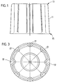
- the outer contour of the rolling piston shown corresponds to a truncated cone.
- the outer wall 11 of the rolling piston is provided on the outside with beads 17, 19 which extend axially from the head region 13 to the foot region 15.
- the beads 17, 19 are distributed over the circumference at an angle of 45 o to each other.
- Two diametrically opposite beads 19 have a greater depth than the other beads 17.
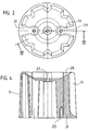
- two reinforcing ribs 21 (FIG. 2 and FIG. 4) extending radially inward from the jacket wall extend axially from the head region 13 in the interior of the rolling piston to foot area 15 through.
- mounting holes 23 are made, via which the rolling piston on a vehicle part, for. B. an air spring support arm can be attached.
- the beads 17, 19 run closed in the foot region 15 to the outside up to the maximum diameter of the rolling piston.
- the cup-shaped rolling piston has a trough-shaped bottom 25 which extends radially inwards and which has a central bore 27 for receiving a fastening bolt (not shown here), which is vulcanized onto the bottom of the bellows, for the non-positive connection of the bellows air spring to the rolling piston serves.
- the rolling fold of the rolling bellows moves up and down on the casing wall 11 of the rolling piston.
- the beads increase the bending moments of the jacket wall.
- the beads also increase the buckling stiffness of the rolling piston.
- the large shape and kink stability is achieved through the beaded, open outer contour of the rolling piston.
Landscapes
- Engineering & Computer Science (AREA)
- General Engineering & Computer Science (AREA)
- Mechanical Engineering (AREA)
- Fluid-Damping Devices (AREA)
- Vehicle Body Suspensions (AREA)
- Rolls And Other Rotary Bodies (AREA)
Claims (7)
- Piston de rebroussement en forme de boisseau, destiné à un ressort pneumatique à soufflet se rebroussant et contre la paroi de l'enveloppe duquel un pli de rebroussement d'un soufflet se rebroussant du ressort pneumatique à soufflet se rebroussant prend appui lors d'une compression, caractérisé en ce que la paroi de l'enveloppe comporte des moulures qui sont orientées essentiellement dans la direction de la longueur du piston de rebroussement, les moulures (17, 19) aboutissant dans la région du pied (15) du piston de rebroussement en étant fermés dans la paroi de l'enveloppe (11).
- Piston de rebroussement selon la revendication 1, caractérisé en ce que la sortie des moulures (17, 19) aboutissant dans la région du pied (15) atteint le diamètre maximal du piston de rebroussement.
- Piston de rebroussement selon l'une des revendications 1 et 2, caractérisé en ce que la paroi de l'enveloppe (11) comporte des nervures intérieures continues de raidissement (21) dans la région desquelles les moulures (19) sont plus profondes que les moulures (17) des autres régions de la paroi de l'enveloppe (11).
- Piston de rebroussement selon la revendication 3, caractérisé en ce que des trous de fixation (23) sont placés dans le fond des nervures de raidissement (21).
- Piston de rebroussement selon l'une des revendications 1 à 4, caractérisé en ce que le piston de rebroussement est en matière plastique armée de fibres et dans laquelle les fibres sont orientées en majeure partie dans la direction de l'axe de la paroi de l'enveloppe (11).
- Piston de rebroussement selon l'une des revendications 1 à 5, caractérisé en ce que le piston de rebroussement est fermé de manière étanche dans la région du pied (15) par une plaque de fond.
- Piston de rebroussement selon l'une des revendications 1 à 6, caractérisé en ce que le contour extérieur du piston de rebroussement s'élargit progressivement vers la région du pied (15).
Applications Claiming Priority (2)
| Application Number | Priority Date | Filing Date | Title |
|---|---|---|---|
| DE4008187 | 1990-03-15 | ||
| DE4008187A DE4008187A1 (de) | 1990-03-15 | 1990-03-15 | Abrollkolben fuer den rollbalg einer rollbalg-luftfeder |
Publications (2)
| Publication Number | Publication Date |
|---|---|
| EP0446476A1 EP0446476A1 (fr) | 1991-09-18 |
| EP0446476B1 true EP0446476B1 (fr) | 1994-06-29 |
Family
ID=6402205
Family Applications (1)
| Application Number | Title | Priority Date | Filing Date |
|---|---|---|---|
| EP90125253A Expired - Lifetime EP0446476B1 (fr) | 1990-03-15 | 1990-12-21 | Piston de déroulage pour le soufflet roulant d'un ressort pneumatique à soufflet roulant |
Country Status (5)
| Country | Link |
|---|---|
| US (1) | US5180146A (fr) |
| EP (1) | EP0446476B1 (fr) |
| JP (1) | JPH04211740A (fr) |
| AT (1) | ATE108005T1 (fr) |
| DE (2) | DE4008187A1 (fr) |
Families Citing this family (20)
| Publication number | Priority date | Publication date | Assignee | Title |
|---|---|---|---|---|
| US5437436A (en) * | 1993-08-20 | 1995-08-01 | Ni-Tech, Inc. | Stand-alone gas spring |
| US5535994A (en) * | 1993-11-30 | 1996-07-16 | The Goodyear Tire & Rubber Company | Composite air spring piston |
| DE19710849B4 (de) * | 1997-03-15 | 2009-04-09 | Bpw Bergische Achsen Kg | Luftfeder für Luftfederachsen |
| EP0942193A3 (fr) * | 1998-03-11 | 2000-06-07 | BRIDGESTONE/FIRESTONE, Inc. | Vérin pneumatique à cannelures |
| DE19910196A1 (de) * | 1999-03-09 | 2000-09-14 | Contitech Luftfedersyst Gmbh | Dreh- und/oder Hubvorrichtung |
| HU224800B1 (en) * | 1999-07-07 | 2006-02-28 | Freudenberg Carl Kg | Pneumatic spring system |
| DE10004122C2 (de) * | 2000-01-31 | 2002-10-31 | Zf Sachs Ag | Luftfeder mit einem Rollbalg |
| DE10224287B4 (de) * | 2001-06-15 | 2006-07-13 | Vibracoustic Gmbh & Co. Kg | Luftfederanordnung |
| DE102004015602B4 (de) * | 2004-03-30 | 2011-08-18 | Continental Teves AG & Co. OHG, 60488 | Luftfedereinrichtung |
| DE102004023561A1 (de) * | 2004-05-13 | 2005-12-08 | Vibracoustic Gmbh & Co. Kg | Luftfederanordnung |
| DE102004030335A1 (de) * | 2004-06-23 | 2006-01-19 | Contitech Luftfedersysteme Gmbh | Luftfeder mit einem Abrollkolben und einem Rollbalg mit mindestens einem anvulkanisierten Befestigungsteil |
| ITMI20050211A1 (it) * | 2005-02-14 | 2006-08-15 | Stuani S P A | Pistone perfezionato per molle ad aria applicabile a sospensioni di autoveicoli rimorchi semirimorchi |
| US7500659B2 (en) * | 2005-04-07 | 2009-03-10 | Bfs Diversified Products, Llc | Air spring assembly and method |
| US8186657B2 (en) | 2007-09-06 | 2012-05-29 | Firestone Industrial Products Company, Llc | Air spring modular piston |
| US20090200717A1 (en) * | 2008-02-08 | 2009-08-13 | Veyance Technologies, Inc. | Air spring piston |
| CN102187113B (zh) * | 2008-10-31 | 2013-05-15 | 株式会社F.泰克 | 螺旋弹簧用防振阻尼器 |
| EP2488770B1 (fr) * | 2009-10-14 | 2022-12-14 | Firestone Industrial Products Company, LLC | Élément d'extrémité, ensemble ressort à gaz et procédé |
| DE112012002716T5 (de) * | 2011-06-30 | 2014-03-27 | Firestone Industrial Products Co. Llc | Gasfederendteil sowie dasselbe beinhaltende Gasfederanordnung |
| DE102015108519B3 (de) * | 2015-05-29 | 2016-07-28 | Saf-Holland Gmbh | Stützeinheit |
| DE102018216989A1 (de) * | 2017-10-04 | 2019-04-04 | Continental Teves Ag & Co. Ohg | Druckkörper für ein Druckluftsystem |
Family Cites Families (9)
| Publication number | Priority date | Publication date | Assignee | Title |
|---|---|---|---|---|
| DE259138C (fr) * | 1912-07-11 | |||
| DE1127729B (de) * | 1957-02-19 | 1962-04-12 | Phoenix Gummiwerke Ag | Abrollkoerper aus Metall, Gummi oder Kunststoff fuer einen Stuelpbalg von Luftfedern, insbesondere fuer Kraftfahrzeuge |
| US2988353A (en) * | 1957-05-09 | 1961-06-13 | Gen Motors Corp | Pneumatic spring construction |
| DE1285792B (de) * | 1966-11-07 | 1968-12-19 | Continental Gummi Werke Ag | Luftfeder mit einem verformbare Wandungen und verstaerkte Wuelste aufweisenden Balg |
| CA1097380A (fr) * | 1977-12-20 | 1981-03-10 | William C. Pierce | Amortisseur pneumatique |
| US4506910A (en) * | 1982-09-21 | 1985-03-26 | Granning Suspensions, Inc. | Automotive vehicle suspension |
| IT1205188B (it) * | 1987-06-26 | 1989-03-15 | Pirelli | Miglioramenti nelle molle ad aria |
| DE3824542A1 (de) * | 1988-07-20 | 1990-01-25 | Sauer Achsenfab | Tauchkolbenanordnung |
| US5060916A (en) * | 1988-07-20 | 1991-10-29 | Otto Sauer Achsenfabrik Keilberg | Plunger piston system |
-
1990
- 1990-03-15 DE DE4008187A patent/DE4008187A1/de not_active Withdrawn
- 1990-12-21 AT AT90125253T patent/ATE108005T1/de not_active IP Right Cessation
- 1990-12-21 DE DE59006314T patent/DE59006314D1/de not_active Expired - Fee Related
- 1990-12-21 EP EP90125253A patent/EP0446476B1/fr not_active Expired - Lifetime
-
1991
- 1991-03-14 JP JP3049889A patent/JPH04211740A/ja active Pending
- 1991-03-15 US US07/670,307 patent/US5180146A/en not_active Expired - Fee Related
Also Published As
| Publication number | Publication date |
|---|---|
| JPH04211740A (ja) | 1992-08-03 |
| EP0446476A1 (fr) | 1991-09-18 |
| US5180146A (en) | 1993-01-19 |
| DE4008187A1 (de) | 1991-09-19 |
| ATE108005T1 (de) | 1994-07-15 |
| DE59006314D1 (de) | 1994-08-04 |
Similar Documents
| Publication | Publication Date | Title |
|---|---|---|
| EP0446476B1 (fr) | Piston de déroulage pour le soufflet roulant d'un ressort pneumatique à soufflet roulant | |
| EP2049815B1 (fr) | Ressort à air pour vehicules | |
| DE69010009T2 (de) | Druckfeder. | |
| DE102005059117B4 (de) | Aktuator für ein aktives Fahrwerk eines Kraftfahrzeugs | |
| EP0351678B1 (fr) | Dispositif à piston | |
| EP2605923B1 (fr) | Jambe de force a ressort pneumatique avec le montage souple du piston | |
| DE2353868A1 (de) | Pneumatisches lager und stossdaempfer | |
| DE10050028A1 (de) | Luftfederanordnung | |
| DE2632444A1 (de) | Vibrationen abschirmendes montageelement | |
| DE102009036360B4 (de) | Federbeinlager zum Anschließen an einen Federbeinschaft | |
| DE102005059116A1 (de) | Aktives Fahrwerk für ein Kraftfahrzeug | |
| EP2673529B1 (fr) | Jambe de suspension pneumatique pour un véhicule | |
| EP1261813B2 (fr) | Amortisseur pneumatique comportant un carter en deux parties | |
| DE102018205215B4 (de) | Blattfedereinrichtung für ein Fahrzeug, Fahrwerk mit einer solchen Blattfedereinrichtung sowie ein Verfahren zum Herstellen einer solchen Blattfedereinrichtung und/oder eines solchen Fahrwerks | |
| DE4327883C2 (de) | Luftfeder zur Abstützung eines Fahrzeugkörpers | |
| EP0520143B1 (fr) | Support de moteur réglable | |
| DE10031432B4 (de) | Membran für eine Luftfeder | |
| EP0391075A2 (fr) | Ressort pneumatique à soufflet roulant | |
| WO2011124325A2 (fr) | Ressort pneumatique | |
| WO2010078923A1 (fr) | Jambe élastique pour suspensions de véhicules automobiles présentant un soufflet métallique se présentant sous la forme d'un ressort auxiliaire | |
| EP1979646A1 (fr) | Unite de suspension et d'amortisseur pneumatique a butee de traction | |
| EP1371872B1 (fr) | Arrangement de ressort pneumatique | |
| DE102017217044B4 (de) | Luftfederbein mit verschiebbaren Rollflächensegmenten | |
| EP4180246B1 (fr) | Piston dérouleur | |
| DE10060824A1 (de) | Abrollkolben für eine Rollbalg-Luftfeder |
Legal Events
| Date | Code | Title | Description |
|---|---|---|---|
| PUAI | Public reference made under article 153(3) epc to a published international application that has entered the european phase |
Free format text: ORIGINAL CODE: 0009012 |
|
| AK | Designated contracting states |
Kind code of ref document: A1 Designated state(s): AT BE CH DE DK ES FR GB GR IT LI LU NL SE |
|
| 17P | Request for examination filed |
Effective date: 19911015 |
|
| 17Q | First examination report despatched |
Effective date: 19930305 |
|
| GRAA | (expected) grant |
Free format text: ORIGINAL CODE: 0009210 |
|
| AK | Designated contracting states |
Kind code of ref document: B1 Designated state(s): AT BE CH DE DK ES FR GB GR IT LI LU NL SE |
|
| PG25 | Lapsed in a contracting state [announced via postgrant information from national office to epo] |
Ref country code: DK Effective date: 19940629 Ref country code: IT Free format text: LAPSE BECAUSE OF FAILURE TO SUBMIT A TRANSLATION OF THE DESCRIPTION OR TO PAY THE FEE WITHIN THE PRE;WARNING: LAPSES OF ITALIAN PATENTS WITH EFFECTIVE DATE BEFORE 2007 MAY HAVE OCCURRED AT ANY TIME BEFORE 2007. THE CORRECT EFFECTIVE DATE MAY BE DIFFERENT FROM THE ONE RECORDED.SCRIBED TIME-LIMIT Effective date: 19940629 Ref country code: GR Free format text: LAPSE BECAUSE OF FAILURE TO SUBMIT A TRANSLATION OF THE DESCRIPTION OR TO PAY THE FEE WITHIN THE PRESCRIBED TIME-LIMIT Effective date: 19940629 Ref country code: BE Effective date: 19940629 Ref country code: ES Free format text: THE PATENT HAS BEEN ANNULLED BY A DECISION OF A NATIONAL AUTHORITY Effective date: 19940629 Ref country code: GB Effective date: 19940629 |
|
| REF | Corresponds to: |
Ref document number: 108005 Country of ref document: AT Date of ref document: 19940715 Kind code of ref document: T |
|
| REF | Corresponds to: |
Ref document number: 59006314 Country of ref document: DE Date of ref document: 19940804 |
|
| ET | Fr: translation filed | ||
| PG25 | Lapsed in a contracting state [announced via postgrant information from national office to epo] |
Ref country code: AT Effective date: 19941221 |
|
| PG25 | Lapsed in a contracting state [announced via postgrant information from national office to epo] |
Ref country code: LI Effective date: 19941231 Ref country code: LU Free format text: LAPSE BECAUSE OF NON-PAYMENT OF DUE FEES Effective date: 19941231 Ref country code: CH Effective date: 19941231 |
|
| GBV | Gb: ep patent (uk) treated as always having been void in accordance with gb section 77(7)/1977 [no translation filed] |
Effective date: 19940629 |
|
| EAL | Se: european patent in force in sweden |
Ref document number: 90125253.6 |
|
| PLBE | No opposition filed within time limit |
Free format text: ORIGINAL CODE: 0009261 |
|
| STAA | Information on the status of an ep patent application or granted ep patent |
Free format text: STATUS: NO OPPOSITION FILED WITHIN TIME LIMIT |
|
| 26N | No opposition filed | ||
| REG | Reference to a national code |
Ref country code: CH Ref legal event code: PL |
|
| PGFP | Annual fee paid to national office [announced via postgrant information from national office to epo] |
Ref country code: NL Payment date: 19951122 Year of fee payment: 6 |
|
| PGFP | Annual fee paid to national office [announced via postgrant information from national office to epo] |
Ref country code: SE Payment date: 19951127 Year of fee payment: 6 |
|
| PG25 | Lapsed in a contracting state [announced via postgrant information from national office to epo] |
Ref country code: SE Effective date: 19961222 |
|
| PG25 | Lapsed in a contracting state [announced via postgrant information from national office to epo] |
Ref country code: NL Effective date: 19970701 |
|
| NLV4 | Nl: lapsed or anulled due to non-payment of the annual fee |
Effective date: 19970701 |
|
| EUG | Se: european patent has lapsed |
Ref document number: 90125253.6 |
|
| PGFP | Annual fee paid to national office [announced via postgrant information from national office to epo] |
Ref country code: DE Payment date: 20081121 Year of fee payment: 19 |
|
| PGFP | Annual fee paid to national office [announced via postgrant information from national office to epo] |
Ref country code: FR Payment date: 20100108 Year of fee payment: 20 |
|
| PG25 | Lapsed in a contracting state [announced via postgrant information from national office to epo] |
Ref country code: DE Free format text: LAPSE BECAUSE OF NON-PAYMENT OF DUE FEES Effective date: 20100701 |