EP0445927A2 - Système d'analyse des odeurs - Google Patents
Système d'analyse des odeurs Download PDFInfo
- Publication number
- EP0445927A2 EP0445927A2 EP91301142A EP91301142A EP0445927A2 EP 0445927 A2 EP0445927 A2 EP 0445927A2 EP 91301142 A EP91301142 A EP 91301142A EP 91301142 A EP91301142 A EP 91301142A EP 0445927 A2 EP0445927 A2 EP 0445927A2
- Authority
- EP
- European Patent Office
- Prior art keywords
- gas
- sample
- carrier gas
- natural gas
- detector
- Prior art date
- Legal status (The legal status is an assumption and is not a legal conclusion. Google has not performed a legal analysis and makes no representation as to the accuracy of the status listed.)
- Withdrawn
Links
Images


Classifications
-
- G—PHYSICS
- G01—MEASURING; TESTING
- G01N—INVESTIGATING OR ANALYSING MATERIALS BY DETERMINING THEIR CHEMICAL OR PHYSICAL PROPERTIES
- G01N30/00—Investigating or analysing materials by separation into components using adsorption, absorption or similar phenomena or using ion-exchange, e.g. chromatography or field flow fractionation
- G01N30/02—Column chromatography
- G01N30/62—Detectors specially adapted therefor
- G01N30/64—Electrical detectors
Definitions
- the field of the present invention is analytical chemistry, and more particularly, gas chromatography, and still more particularly, the quantitative and qualitative evaluation of odorants in natural gas.
- the characteristic odor of natural gas is a principal means of alerting the consuming public to potentially dangerous gas leaks.
- This odor is not necessarily indigenous to natural gas but is maintained by the addition of various odiferous compounds such as mercaptans and organic sulfides.
- concentration of such odorant compounds in natural gas must be maintained constant so as to provide sufficient warning of significant leaks while avoiding the occurrence of false alarms.
- Sensitivity to odorants vary substantiallar from the individual to individual and even on a day to day basis for a given individual.
- Such a device should provide increased sensitivity and decreased response time, and should be class selective in order to selectively measure hydrogen sulfides, mercaptans and organic sulfides while remaining insensitive to natural gas hydrocarbon compounds. Further, the device should be rugged and insensitive to motion and position.
- Coquad "Odorant Measurement And Control In A Distribution System,” proposes an odorant measurement system known as the “Medor,” which includes a carrier gas-injection system employing a chromatographic column in combination with a detector formed from a glass or methyl polymethacrylate container having two platinum gauze electrode grids welded 30 millimeters apart in a glass tube and separately connected to an amplifier or to a recorder by a platinum wire.
- An electrolyte a 10% solution of chromic oxide in distilled water, is contained in the container into which the tube with the electrode dips.
- This apparatus appears not to be suited for rugged, portable operation, uses corrosive toxic chemicals, requires bottled gas, and may lack sufficient sensitivity and response time. Brody, et al.
- 1,512,893 provides a method and apparatus for quantitative determination of hydrogen sulfide in illuminating and other gas wherein a gas sample is passed over a strip of hardened filter paper spotted with solutions of different salts that are differently reactive to different concentrations of hydrogen sulfide in the gas for the formation of sulfides, of different coloration.
- 3,061,4144 discusses a method and apparatus for analyzing gases containing low molecular weight mercaptans and/or hydrogen sulfide wherein an aqueous iodine solution is contacted with the sample gas, causing a change in the acidity of the aqueous iodine solution, depending on the concentration of the low molecular weight mercaptans and/or hydrogen sulfide.
- Jones U.S. Patent No.
- 3,114,609 proposes a method and apparatus for mercaptan analysis of hydrocarbon streams, wherein reagent and gas streams are directed through metering pumps, scrubber columns, a reactive column (for the reagent stream) and a pair of conductivity cells placed in a bridge circuit to produce conductivity differentials between variously treated portions of the gas stream.
- reagent and gas streams are directed through metering pumps, scrubber columns, a reactive column (for the reagent stream) and a pair of conductivity cells placed in a bridge circuit to produce conductivity differentials between variously treated portions of the gas stream.
- 3,208,828 and 3,475,129 provides a method and device for determining whether an indicator such as an odorant has been added to a gas stream and is present in a required concentration, wherein a sample is routed to a detector tube made of transparent material such as glass, and which is provided with uniform sections of impregnated silica gel and unimpregnated silica gel or sand of different color whose length is adjusted so that a color change of each section or zone, corresponds to a level of 10ppm mercaptan in a prescribed volume of gas.
- the impregnating material is palladium chloride.
- the volume of the gaseous mixture is controlled by a balloon fitted in a conventional volume ring. Kniebes, et al. (U.S.
- Patent No. 3,686,930 proposes a method and apparatus for measuring odor level in natural gas wherein a gas sample is carried by a nitrogen carrier gas through a chromatographic column to a flame photometric detector.
- Mitchell proposes a method for determining the concentration of organic sulphur compounds in a gas employing a gas chromatograph fitted with a flame ionization detector and a recorder.
- Pierce U.S. Patent Nos.
- 3,718,434 and 3,437,446) provides an apparatus and method for detecting gaseous contaminants such as SO2, SO3 and H2S in ambient air, stack gases, flue gas streams, automotive exhaust, etc., which monitors the poisoning effect (and contaminant concentration) by measuring changes in the flow rate for a gas diffusing through a selectively permeable metallic element.
- Cheng, et al. U.S. Patent No. 3,820,958 proposes an apparatus and method for determining the presence of hydrogen sulfide in a gas mixture such as air, wherein silver is deposited on a thin dielectric film, exposed to the hydrogen sulfide containing gas mixture, and measuring the electrical resistance across the film before and after exposure to hydrogen sulfide.
- Verma, et al. proposes a method and apparatus for measuring the presence of mercaptan-based odorants in natural, synthetic, or liquid petroleum gases and the like, wherein a gas to be tested is injected into multiple compartments, each containing a different reagent. The reagents are mixed together and the resultant color is checked against a standard color slide or the like to identify the amount of mercaptan-based odorants in parts per million present in the sample of gas.
- Vincent, et al. U.S. Patent No.
- 4,526,755 proposes a gas analyzer for natural gas to determine the existence of and concentration of wanted and unwanted sulfur compounds and odorizing agents by providing scrubbers of different kinds delivering gases in different combinations to electrical measurement apparatus from which corresponding signals are subtracted.
- Eads U.S. Patent No. 3,650,696 proposes a method for sampling ambient air containing sulfur compounds and separating, identifying and quantitatively monitoring each compound wherein a gaseous sample is collected in substantially sulfur-free methanol and passed through a gas chromatograph column to separate the sulfur compounds. From the gas chromatograph the separated sulfur compounds go through a pyrolysis furnace where they are oxidized to sulfur dioxide, and then into a microcoulometer for titration.
- the present invention is directed to a portable natural gas odorant analyzer system including a chromatograph column for temporally separating components, an electrochemical detector for oxidizing odorant components, and a potentiostat for controlling an electrical potential across the detector electrodes and providing an electrical output signal proportional to the concentration of gas components.
- Fig. 1 is an exterior plan view of a portable natural gas odorant analyzer constructed in accordance with the present invention.
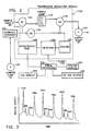
- Fig. 2 is a diagrammatic illustration of the odorant analyzer of fig. 1.
- Fig. 3 is a representative chromatogram with odorants in actual natural gas obtained with the odorant analyzer of fig. 1 with peaks corresponding to hydrogen sulfide (H2S), methyl mercapton (MM), dimethyl sulfide (DMS), and t-butyl mercapton (TBM).
- H2S hydrogen sulfide
- MM methyl mercapton
- DMS dimethyl sulfide
- TBM t-butyl mercapton
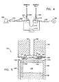
- Fig. 4 is a diagrammatic illustration of a gas delivery system of the odorant analyzer of fig. 1.
- Fig. 5 is a detailed sectional illustration of a gas detector employed in the odorant analyzer of fig. 1.
- Fig. 6A is a chromatogram of the natural gas odorants isopropyl mercapton (IPM) and normal mercapton (NPM) at concentrations of 0.09 and 0.08, repsectively.
- IPM isopropyl mercapton
- NPM normal mercapton
- Fig. 6B is another chromatogram of the natural gas odorants t-butyl mercapton (TBM) and methyl ethyl sulfide (MES) at concentrations of 0.14 and 0.16 PPMV, respectively.
- TBM t-butyl mercapton
- MES methyl ethyl sulfide
- Fig. 7 is a chromatogram of odorized natural gas resulting from injections at ten minute intervals.
- Fig. 8 illustrates typical calibration curves for use with the odorant analyzer of fig. 1.
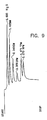
- Fig. 9 is a chromatogram illustrating class selectivity in an odorant analyzer constructed in accordance with the present invention.
- Fig. 10 is a chromatogram illustrating rapid response achieved in an odorant analyzer constructed in accordance with the present invention.
- Fig. 11 is a chromatogram illustrating insensitivity to movement in an odorant analyzer constructed in accordance with the present invention.
- Fig. 12 is an alternative embodiment gas detector constructed in accordance with the present invention.
- Fig. 13 is a plan view of an alternative embodiment electrode assembly constructed in accordance with the present invention.
- Fig. 14 is a side view of the electrode assembly of Fig 13.
- the invention may be embodied in structural form in a housing 10 having an instrument panel 12 providing an operator-machine interface. Disposed on the instrument panel 12 is a keypad 14 for data entry and a display output 16 for operator messages. Data is outputted via an onboard ink cartridge printer 18, and optionally through a serial data port 19. Status lights 20-26 provide a visual indication of various conditions of the analyzer.
- a carrier gas pressure indicator 28 indicates carrier gas line pressure.
- a sample gas inlet 30 provides a natural gas input to the analyzer.
- the analyzer's 12 v rechargeable battery (not shown) may be charged through a charge connector 32. The battery may be of conventional design and preferably provides at least eight hours continuous operation between chargings.
- a temperature regulated module 100 which provides a temperature controlled environment for analyzer components.
- These components include a gas chromatograph column 102 in fluid communication with an electrochemical (ECC) detector 104, which vents from the analyzer to a vent 106.
- ECC electrochemical
- the detector 104 provides a situs for oxidizing and reducing natural gas samples depending upon the applied detector bias.
- the detector bias is controlled by a potentiostat 108 which also generates an electrical output signal representing the concentration of odorants present in the detector 104.
- the temperature regulated module 100 also contains components of the gas delivery system used to provide a gas sample to the column and detector.
- the gas delivery system components within the temperature regulated module 100 include three solenoid valves of conventional design, those being a first gas flow control valve 110, a second gas flow control valve 112, and a third gas flow control valve 116.
- a sample loop 114 of conventional design is provided between the valves 112 and 116. The sample loop 114 provides a temporary storage area for storing a sample gas charge prior to delivery to the column 102 and detector 104.
- Completing the gas delivery system is the sample inlet 30 extending from the front face of the housing 10 to the second gas flow control valve 112, a carrier gas pump 120 extending to a charcoal scrubber 122 which extends into the temperature regulated module 100 to the gas flow control valves 110 and 112, and, lastly, a gas sample pump 124 receiving an input from the gas flow control valve 116.
- the sample pump output is vented to atmosphere.
- the first gas flow control valve 110 includes an inlet in fluid communication with the scrubber 122, an outlet in fluid communication with the column 102, and solenoid actuated valving for selectively interrupting the flow of carrier gas between the valve inlet and outlet.
- the second gas flow control valve 112 includes a first inlet in fluid communication with the inlet of the first gas flow control valve 110, a second inlet in fluid communication with the sample inlet 30, an outlet in fluid communication with the sample loop 114 and solenoid actuated valving for selectively interrupting gas flow between one of the first and second valve inlets and the valve outlet.
- the third gas flow control valve 116 includes a valve inlet in fluid communication with the sample loop 114, a first valve outlet in fluid communication with the outlet of the first gas flow control valve 110, a second valve outlet in fluid communication with the sample pump 124 and solenoid actuated valving for selectively interrupting gas flow between the valve inlet and the first and second valve outlets.
- the gas delivery system is configured to operate in a carrier gas delivery mode and in a sample gas injection mode such that a gas sample is first loaded into the gas delivery system and then carried to the column and detector by the carrier gas.
- solenoid valves 112 and 116 are actuated so as to selectively interrupt fluid communication with the solenoid valve 110.
- the solenoid valve 112 selectively opens to the sample inlet 30 while the solenoid valve 116 selectively opens to the gas sample pump 124.
- the pump 124 is activated to draw a gas sample through the sample loop 114.
- the solenoid valve 110 is simultaneously opened to maintain constant flow of carrier gas through the column 102 and detector 104.
- Analysis begins when the solenoid valves 112, 116 and 110 are de-energized, such that the valve 110 is closed, the valve 112 is closed to the sample inlet 30 and opened to the valve 110, and the valve 116 is closed to the sample pump 124 and opened to the valve 110. This causes the contents of the sample loop 114 to be injected into the head of the column 102.
- Each of the odorant compounds proceeds through the chromatographic column 102 at a different velocity and elute separately through the detector 104. Each compound, as it elutes through the detector, causes a current to flow through the detector in proportion to the mass of odorant originally injected.
- each odorant compound is qualitatively identified by its retention time through column 102 and is quantitatively determined by measurement of the current generated by the potentiostat 108.
- the column 102 is maintained at a constant temperature of about 45°C in the temperature regulated module to assure constant retention times.
- Flow restrictors 126 and 128, shown in fig. 4, are present to assure constant sample gas injection volume. Without these restrictors, various amounts of sample may escape during the injection process, thereby leading to variations in the detector response.
- the column 102 is adapted to obtain maximum temporal separation of odorant compounds in a minimum time period. Moreover, the column is compact, operates at relatively low pressures (preferably about 16 psi, or between about 10 and 20 psi, and no more than 50 psi), is inert to odorant compounds and at the same time is physically robust. Operating temperature is slightly above ambient, outdoor conditions, at 45° C.
- the column 102 is formed from a mixture of 18.5% SP2100 TM, a low viscosity silicon oil sold by Supelco, Inc., 1.1% FLUORAD 430 TM, sold by 3M Company, 1.3% dodecanethiol and 100/120 mesh chromosorb w HP. The mixture is packed in an FEP TEFLON TM tube of 1/16 ⁇ OD and 1/32 ⁇ ID. The tube is formed into a 1 inch coil and formed into a "U" shape about 1 1/2 ⁇ to 2 ⁇ long.
- the detector 102 may be seen as including a lower fluid containing cell body 130, an upper exposure cap 132 and an electrochemical cell assembly 134.
- the cell body 130 which may be formed from any suitable non-conductive structurally rigid material, includes a cylindrical wall 136 for containing a fluid, an upper circular chamber defining surface 140 and a cylindrical lip 142 extending upwardly from the chamber-defining surface 140.
- the chamber-defining surface 140 has an aperture 144 formed therein.
- a polymeric wick 146 which may be formed from any suitable hydrophilic polymeric material, rests on top of the chamber-defining surface 140 and extends through the aperture 144 into the fluid reservoir 138 in the cell body 130, which is typically filled with distilled water.
- the exposure cap 132 Disposed adjacent the top of the circumferential lip 142 of the cell body 130 is an elastomeric ring member 148 which seals off the chamber formed between the cell body 130 and the upper exposure cap 132 when these components are joined together.
- the exposure cap 132 which may also be formed from any suitable non-conductive structurally rigid material, includes a cylindrical body portion having respective gas inlet and outlet passages 150 and 151.
- the passages 150 and 151 extend through the body of the exposure cap 132 to an interior recess 152 formed in the lower chamber-defining face 154 of the exposure cap 132.
- the elastomeric ring 148 is disposed between the lower chamber-defining surface 134 of the exposure cap 132 and the circumferential lip 142 formed on the cell body 130.
- the electrochemcial cell 134 includes a polymeric electrolyte membrane 154 which may be advantageously formed from perflourocarbon, which is commercially available from Dupont Corporation under the tradename NAFION TM. Attached to the NAFION TM membrane 154 are three metallic electrodes, a working electrode 156, a counter electrode 158 and a reference electrode 160. The working electrode 156 may be advantageously formed from gold, while the counter and reference electrode 158 and 160 may be advantageously formed from platinum. Each electrode is connected to the potentiostat 108, which may be of conventional design. The NAFION TM membrane 154 is hydrated by the polymeric wick 146.
- the NAFION TM membrane acts as a solid phase ionic conductor and thus serves as the electrolyte for the electrochemical cell.
- the detector 102 confines the influent gases from the column 102 to a small volume about the working electrode 156. Moreover, because hydration is provided using the polymeric wick 146, the detector is not sensitive to movement and orientation. In operation, the electrical potential of the working electrode is maintained sufficiently oxidizing to assure the oxidation of sulfur compounds while avoiding oxidation of potential interferences or water. In the absence of a sulfur compound, a small but constant background current occurs at the working electrode. However, as odorant compounds enter the exposure chamber, they diffuse to the working electrode where they are rapidly oxidized and produce a current roughly proportional to their concentration in the sample gas. Under constant chromatographic conditions of constant flow rate and consistent injection volume, the current at the working electrode is proportional to the mass and concentration of the injected odorant.
- a signal processing module 200 which is preferably a micro-programmable information processing apparatus.
- the signal processing unit 200 selectively provides output to a printer module 202 which drives the printer 18, a display module 204 which drives the liquid crystal display 16, and serial data output module 206 connected to the serial data output 19, for outputting information to a separate information processing system.
- the signal processing unit 200 may be conveniently programmed to control the odorant analyzer in two functional modes. In this respect, it will be understood that the signal processing unit 200 is in electrical communication with not only the potentiostat 108, but the solenoid valves 110, 112 and 116, as well as the carrier pump 120 and the sample pump 124. Thus, the signal processing unit 200 controls all analyzer operations.
- a preferred potentiostat bias is +300 mv.
- a concentration profile such as that shown in fig. 3 can be readily obtained.
- detection of typical odorant compounds such as IPM, NPM, TBM, and MES is readily achieved at typical lower level concentrations of 0.09 ppm for IPM, 0.08 ppm for NPM, 0.14 ppm for TBM and 0.16 ppm for MES.
- the analyzer is sensitive enough for all odorant analysis applications.
- the response to natural gas odorants over the response to saturated hydrocarbon components of natural gas is on the order of 10 ⁇ 6 or less.
- the response of carbonyl sulfide, olefins and carbon disulfide to odorants is on the order of 5 x 10 ⁇ 3, 5 x 10 ⁇ 4 and less than 5 x 10 ⁇ 3, respectively.
- the analyzer may be programmed to repeatedly inject a sample, as for example, every 10 minutes. While most odorants may be readily detected within a 5 minute cycle, THT does not elute until 17.57 minutes, after the second injection. Thus, prudent practice may dictate a 10 minute cycle.
- current response from the potentiostat 108 may be correlated directly to odorant concentration level using calibration curves for each odorant.
- Fig. 8 shows such curves for IPM and NPM.
- the processor 200 includes calibration programming to provide a direct odorant concentration output.
- Fig. 9 illustrates a concentration profile at a bias of -300 mv of a mixture of H2S, mercaptans and organic sulfides. The chromatogram shows clear peaks for H2S and the mercaptans, but shows no response to the two organic sulfides in the mixture (dimethyl sulfide and methyl ethyl sulfide).
- Tables I and II illustrate detector relative response factors (na/ppm)/(na/ppm for TBM) at various cell bias values. It will be observed that at a bias of less than about -750 mv, H2S, but not mercaptans or organic sulfides, provoke significant detector response. At biases between about -300 mv and -0 mv, H2S and mercaptans, but not organic sulfides illicit detector response. At biases more positive than about +300 mv, significant organic sulfide readings may be obtained.
- Fig. 11 further illustrates detector response to shaking, moving and inclining the detector. As indicated, such movement has little effect on the chromatogram output.
- an alternative detector embodiment is shown as including a cylindrical exposure cap 300, a cylindrical housing 302 and a cylindrical end cap 304.
- the housing 302 and end cap 304 are conveniently formed from polypropylene while the exposure cap 300 is conveniently formed from TEFLON (trademark).
- the exposure cap 300 has an upper cylindrical portion 306 of enlarged diameter (about 1.5 ⁇ dia.) and a reduced diameter lower cylindrical portion 308 (about 1.1 ⁇ dia.). Section 306 is about 1/4 ⁇ while section 308 is about 1/8 ⁇ high.
- a gas inlet 310 and a gas outlet 312 Disposed in the top surface of the upper cylindrical portion 306 are a gas inlet 310 and a gas outlet 312, connected, respectively, by gas ports 314 and 316 to a gas exposure chamber 318 formed on the lower surface of the lower reduced diameter section 308 of the exposure cap 300.
- the gas inlet 310 and gas outlet 312 may be formed from a pair of 1/4 - 28 threaded ports.
- the exposure chamber 318 may be formed from a 1/4 ⁇ diameter X 1/16 ⁇ deep port.
- the inlet and outlet ports 314 and 316 may be about 1/8 ⁇ diameter.
- the housing 302 is generally cylindrical, having an outside diameter of about 1.5 ⁇ and an inside diameter of about 1.1 ⁇ , and includes an upper recess 320 formed by an upper electrode support wall 322.
- the support wall 322 is positioned at a depth of at least 1/8 ⁇ to allow insertion of the lower cylindrical section 308 of the exposure cap 300 into the recess 320, such that the shoulder formed by the transition between the upper section 306 and the lower section 308 rests on top of the housing 302.
- the electrode support wall 322 includes a pair of slots 324 extending through the support wall 322 into a fluid reservoir 326 within the housing 302.
- the slots are approximately 5/16 ⁇ long and 3/32 ⁇ wide to permit insertion of a polyester wick (not shown) therethrough.
- the polyester wick is approximately 6 ⁇ long and 1/4 ⁇ wide. Both ends are inserted through the slots 329 and extend approximately 2 3/4 ⁇ below the support wall 322 into the fluid reservoir 326.
- a 1 ⁇ OD, 5/8 ⁇ ID, double-sided tape ring (not shown) is placed over the polyester wick.
- the NAFION TM electrode assembly is then placed over the tape and 1/32 ⁇ X 1/8 ⁇ notches are cut in the upper wall of the housing 302 to accommodate the cell leads.
- a 1 ⁇ OD, 3/8 ⁇ ID silicon rubber gasket (not shown) is then taped to the bottom of section 308 of the exposure cap 300, centered on the exposure chamber 318, and the cap 300 is placed into the housing 302.
- Conventional connectors may be used to affix the cap 300 to the housing 302.
- the fluid reservoir 326 may then be filled with distilled water and the end cap 304 attached by conventional means to the bottom of the housing 302 to seal the fluid reservoir 326.
- an electrode assembly 400 includes a pair of upper and lower 1 ⁇ diameter NAFION TM disks 402 and 404.
- a working electrode is formed on the lower surface of the disk 404 from a 3/8 inch gold powder electrode disk 406 overlayed with a 3/8 ⁇ gold or platinum mesh current collector disk 408.
- the gold powder preferably has a surface area of about 0.51 square meters per grin.
- a counter electrode is formed on the upper surface of the disk 404 from a pair of platinum or platinum black electrode strips 410 overlayed by a pair of platinum mesh current collector strips 412.
- a reference electrode is formed on the upper surface of the disk 404 from a pair of platinum or platinum black electrode strips 414 overlayed by a pair of platinum mesh current collector strips 416.
- the counter and reference electrodes may also be generally semicircular in order to increase electrode area. These electrodes may advantageously formed by dividing a platinum or platinum black disk into 2/3 size and 1/3 size portions, the larger portion forming the counter electrode and the smaller portion forming the reference electrode.
- the 1 ⁇ NAFION TM disks are, first boiled in 1:3 H2O:H2SO4. Electrode leads of 2 cm 10 mil Platinum wire are spot-welded to the working, counter and reference electrode mesh current collectors. The counter and reference electrodes are placed on the upper NAFION TM disk with ZYTEX TM backings and tack soldered thereto. The electrodes are then covered with a TEFLON TM sheet and pressed for 15 seconds at 250 psi and 300° F. When cool the Zytex backing may be peeled off and the platinum mesh current collector strips affixed thereto.
- the lower NAFION TM disk is then pressed over the counter and reference electrodes and pressed against the upper NAFION TM disk for 15 seconds at 250 psi and 300° F.
- the working electrode 406 with a ZYTEX TM backing is tacked soldered to the bottom of the lower NAFION TM disk 404 and pressed thereto for 15 seconds at 250 psi and 300° F.
- the ZYTEX TM should then be peeled off.
- the gold or platinum mesh current collector 408 is then placed over the gold electrode 406.
- a third NAFION TM disk with the 1/4 ⁇ diameter hole in the center may then be placed over the working electrode.
- the third NAFION TM disk is covered with Zytex, tacked in place to hold the layers together, and the entire assembly placed in a press and pressed for 1 minute 15 seconds at 300 psi and 300°F.
- the third NAFLON TM disk need not be used.
- the primary functional mode of the odorant analyzer provides the utility technician with a simplified format for obtaining an on-site analysis of the natural gas odorant levels. Secondly, sub-level entry capability is available (via a special password) for the more knowledgeable laboratory user who requires greater flexibility in the operation of the unit.
- the instrument will preferably be a "black-box" which directs the technician through the analysis cycle via prompts on the display 204.
- the display Upon startup the display will read "Warming-up" for approximately 15 minutes while the thermal regulator module and detector reach their setpoints, which is preferably about 45°C. During this time the operator cannot access the keypad 14. Following the "warmup” cycle, the system goes into a ready mode where the operator can choose between a calibration or sample mode. Typically the operator will select the calibrate cycle and be prompted to connect up a calibration source and initiate the cycle by pressing the operate button. Following the calibration cycle, typically five minutes, the unit will turn to the ready mode where the operator is presented with the same two options. Calibration of the analyzer tales two forms. Approximately every three months, it is preferable that a full odorant calibration be performed.
- the full calibration will encompass all odorants that are expected to be present in a user's natural gas supply.
- the results are used to calculate the responses of each odorant relative to a primary target odorant, typically DMS. These relative responses are then entered into the processor program where they are permanently stored.
- the second form of calibration is field calibration, which is performed by the utility technician using a single primary target odorant such as DMS. Based upon the instrument's field response to DMS, the relative responses for the other odorants may be factored accordingly.
- the DMS field standards may be supplied in special, teflon-coated lightweight, aluminum cylinders. These disposable cylinders will preferably have stable concentrations for at least six months.
- the operator will select the "sample” mode, connect the input line to the natural gas source and press the "operate” button.
- the results may be printed and the instrument returned to the "ready” mode.
- the laboratory user who has a working knowledge of gas chromatograph systems is able to gain access to the operating software to change the operational and/or calibration parameters.
- Parameters which typically are altered include:
- the analyzer responds selectively to the presence of sulfur compounds in natural gas and does not respond to other concomitant compounds such as hydrocarbons.
- the device is capable of detecting odorant compounds at levels as low as approximately 0.1 ppm. When used with a gas chromatographic system with a 0.3 ml. injection volume, approximately 30pg of odorant compound can be detected with a signal to noise ratio of approximately 10. This detectability is better than the typical laboratory flame photometric detector by a factor of approximately 10-50.
- the device exhibits quick response time and is fast enough to permit rapid resolution of sequentially eluting chromatographic peals.
- the detector- responds sufficiently rapidly to resolve approximately 7 odorants in 5 minutes.
- the device is insensitive to motion and orientation.
Landscapes
- Physics & Mathematics (AREA)
- Health & Medical Sciences (AREA)
- Life Sciences & Earth Sciences (AREA)
- Chemical & Material Sciences (AREA)
- Analytical Chemistry (AREA)
- Biochemistry (AREA)
- General Health & Medical Sciences (AREA)
- General Physics & Mathematics (AREA)
- Immunology (AREA)
- Pathology (AREA)
- Sampling And Sample Adjustment (AREA)
Applications Claiming Priority (2)
| Application Number | Priority Date | Filing Date | Title |
|---|---|---|---|
| US48917190A | 1990-03-06 | 1990-03-06 | |
| US489171 | 1990-03-06 |
Publications (2)
| Publication Number | Publication Date |
|---|---|
| EP0445927A2 true EP0445927A2 (fr) | 1991-09-11 |
| EP0445927A3 EP0445927A3 (en) | 1992-03-25 |
Family
ID=23942704
Family Applications (1)
| Application Number | Title | Priority Date | Filing Date |
|---|---|---|---|
| EP19910301142 Withdrawn EP0445927A3 (en) | 1990-03-06 | 1991-02-13 | Odorant analyzer system |
Country Status (1)
| Country | Link |
|---|---|
| EP (1) | EP0445927A3 (fr) |
Cited By (5)
| Publication number | Priority date | Publication date | Assignee | Title |
|---|---|---|---|---|
| EP0640833A1 (fr) * | 1993-08-31 | 1995-03-01 | R.J. Reynolds Tobacco Company | Procédé et dispositif pour un système de surveillance d'émissions en continu en utilisant la chromatographie en phase gazeuse |
| US5801297A (en) * | 1993-09-17 | 1998-09-01 | Alpha M.O.S. | Methods and devices for the detection of odorous substances and applications |
| FR2766524A1 (fr) * | 1997-07-28 | 1999-01-29 | Clextral | Membrane elastique pour une pompe a membrane |
| US20120125076A1 (en) * | 2007-08-31 | 2012-05-24 | Air Liquide Advanced Technologies Us Llc | Portable metered flow apparatus for calibration/bump testing |
| US9581574B2 (en) | 2013-12-06 | 2017-02-28 | Battelle Memorial Institute | Method and device for detecting odorants in hydrocarbon gases |
Citations (3)
| Publication number | Priority date | Publication date | Assignee | Title |
|---|---|---|---|---|
| US3686930A (en) * | 1970-05-07 | 1972-08-29 | Inst Gas Technology | Method for measuring odor level in natural gas |
| US4820386A (en) * | 1988-02-03 | 1989-04-11 | Giner, Inc. | Diffusion-type sensor cell containing sensing and counter electrodes in intimate contact with the same side of a proton-conducting membrane and method of use |
| WO1989008249A1 (fr) * | 1988-02-24 | 1989-09-08 | Matsushita Electric Works, Ltd. | Capteur de gaz electrochimique |
-
1991
- 1991-02-13 EP EP19910301142 patent/EP0445927A3/en not_active Withdrawn
Patent Citations (3)
| Publication number | Priority date | Publication date | Assignee | Title |
|---|---|---|---|---|
| US3686930A (en) * | 1970-05-07 | 1972-08-29 | Inst Gas Technology | Method for measuring odor level in natural gas |
| US4820386A (en) * | 1988-02-03 | 1989-04-11 | Giner, Inc. | Diffusion-type sensor cell containing sensing and counter electrodes in intimate contact with the same side of a proton-conducting membrane and method of use |
| WO1989008249A1 (fr) * | 1988-02-24 | 1989-09-08 | Matsushita Electric Works, Ltd. | Capteur de gaz electrochimique |
Non-Patent Citations (5)
| Title |
|---|
| ANALYTICAL CHEMISTRY vol. 61, no. 6, 15 March 1989, pages 584-589, Columbus, US; J.F. PARCHER et al.: "Solid-State Voltammetry and Polymer Electrolyte Plasticization as a Basis for an Electrochemical Gas Chromatographic Detector" * |
| CHEMICAL ABSTRACTS vol. 86, no. 10, 7 March 1977, page 154, abstract no. 57725v, Columbus, Ohio, US; A. ARCIS et al.: "Novel instrument for selectively determining sulfur compounds present in gases: use of the MEDOR-S method" & C. R. Congr. Ind. Gaz 1975, vol. 92, pages 300-323 * |
| IEEE TRANSACTIONS ON ELECTRON DEVICES vol. 35, no. 6, June 1988, pages 793-799, New York, US; G.J. MACLAY et al.: "Microfabricated Amperometric Gas Sensors" * |
| JOURNAL OF CHROMATOGRAPHY vol. 155, 1978, pages 35-45, Amsterdam, NL; K.F. BLURTON et al.: "Sensitive electrochemical detector for gas chromatography" * |
| JOURNAL OF CHROMATOGRAPHY vol. 286, 23 March 1984, pages 69-78, Amsterdam, NL; J. MACAK et al.: "Determination of sulphur compounds in natural gas by gas chromatography with a flame photometric detector" * |
Cited By (8)
| Publication number | Priority date | Publication date | Assignee | Title |
|---|---|---|---|---|
| EP0640833A1 (fr) * | 1993-08-31 | 1995-03-01 | R.J. Reynolds Tobacco Company | Procédé et dispositif pour un système de surveillance d'émissions en continu en utilisant la chromatographie en phase gazeuse |
| US5801297A (en) * | 1993-09-17 | 1998-09-01 | Alpha M.O.S. | Methods and devices for the detection of odorous substances and applications |
| US5918257A (en) * | 1993-09-17 | 1999-06-29 | Alpha M.O.S. | Methods and devices for the detection of odorous substances and applications |
| FR2766524A1 (fr) * | 1997-07-28 | 1999-01-29 | Clextral | Membrane elastique pour une pompe a membrane |
| US20120125076A1 (en) * | 2007-08-31 | 2012-05-24 | Air Liquide Advanced Technologies Us Llc | Portable metered flow apparatus for calibration/bump testing |
| US9261885B2 (en) * | 2007-08-31 | 2016-02-16 | Air Liquide Advanced Technologies U.S. Llc | Portable metered flow apparatus for calibration/bump testing |
| US9581574B2 (en) | 2013-12-06 | 2017-02-28 | Battelle Memorial Institute | Method and device for detecting odorants in hydrocarbon gases |
| US10379093B2 (en) | 2013-12-06 | 2019-08-13 | Battelle Memorial Institute | Method and device for detecting odorants in hydrocarbon gases |
Also Published As
| Publication number | Publication date |
|---|---|
| EP0445927A3 (en) | 1992-03-25 |
Similar Documents
| Publication | Publication Date | Title |
|---|---|---|
| US5071526A (en) | Acidic gas sensors and method of using same | |
| EP1766384B1 (fr) | Ensemble detecteur de gaz comprenant un ou plusieurs capteurs de gaz et un ou plusieurs sorbeurs, et procede d'utilisation dudit ensemble | |
| US4670405A (en) | Sensor array for toxic gas detection | |
| CA1187773A (fr) | Methode et dispositif d'analyse d'echantillons au titre de leur teneur en azote, hydrogene, soufre ou chlore | |
| US3686930A (en) | Method for measuring odor level in natural gas | |
| SU890993A3 (ru) | Способ определени содержани органических веществ в газах | |
| US6661233B2 (en) | Gas analyzer with real-time broadband monitoring and snapshot selective detection | |
| Barsky et al. | An evaluation of the response of some portable, direct-reading 10.2 eV and 11.8 eV photoionization detectors, and a flame ionization gas chromatograph for organic vapors in high humidity atmospheres | |
| EP0445927A2 (fr) | Système d'analyse des odeurs | |
| US4078981A (en) | CO2 interference free O2 electrode | |
| US3431771A (en) | Universal diffusion-sorption type gas analyzer | |
| Woolfenden | Optimising analytical performance and extending the application range of thermal desorption for indoor air monitoring | |
| Hochheiser et al. | Atmospheric surveillance. Current state of air monitoring technology | |
| Hori et al. | Development of a new respirator for organic vapors with a breakthrough detector using a semiconductor gas sensor | |
| Moore et al. | Hydrogen sulfide measurement and detection | |
| Peach et al. | Air sampling and analysis for gases and vapors | |
| GB2288874A (en) | Reducing gas analysis apparatus | |
| CN211348073U (zh) | 一种测定硫化氢和磷化氢含量的分析装置 | |
| Pellizzari et al. | Evaluation of sampling methods for gaseous atmospheric samples | |
| Gordon et al. | Carbon Monoxide | |
| Applebury | Air pollution abatement by process gas chromatography | |
| Herrick et al. | Measurement of Vapors and Gases | |
| Gordon et al. | Hydrocarbon Analyzers | |
| Radar et al. | 1.28 hydrocarbon Analyzers Toreceiver | |
| Ho et al. | Measurement of Vapor Concentrations |
Legal Events
| Date | Code | Title | Description |
|---|---|---|---|
| PUAI | Public reference made under article 153(3) epc to a published international application that has entered the european phase |
Free format text: ORIGINAL CODE: 0009012 |
|
| AK | Designated contracting states |
Kind code of ref document: A2 Designated state(s): AT BE CH DE DK ES FR GB GR IT LI LU NL SE |
|
| PUAL | Search report despatched |
Free format text: ORIGINAL CODE: 0009013 |
|
| AK | Designated contracting states |
Kind code of ref document: A3 Designated state(s): AT BE CH DE DK ES FR GB GR IT LI LU NL SE |
|
| STAA | Information on the status of an ep patent application or granted ep patent |
Free format text: STATUS: THE APPLICATION IS DEEMED TO BE WITHDRAWN |
|
| 18D | Application deemed to be withdrawn |
Effective date: 19920926 |