EP0445740B1 - Treating machine, in particular automatic punching and bending machine - Google Patents
Treating machine, in particular automatic punching and bending machine Download PDFInfo
- Publication number
- EP0445740B1 EP0445740B1 EP91103327A EP91103327A EP0445740B1 EP 0445740 B1 EP0445740 B1 EP 0445740B1 EP 91103327 A EP91103327 A EP 91103327A EP 91103327 A EP91103327 A EP 91103327A EP 0445740 B1 EP0445740 B1 EP 0445740B1
- Authority
- EP
- European Patent Office
- Prior art keywords
- drive rod
- processing
- machine according
- processing machine
- drive
- Prior art date
- Legal status (The legal status is an assumption and is not a legal conclusion. Google has not performed a legal analysis and makes no representation as to the accuracy of the status listed.)
- Expired - Lifetime
Links
- 238000005452 bending Methods 0.000 title claims description 11
- 238000004080 punching Methods 0.000 title claims description 8
- 238000012545 processing Methods 0.000 claims description 250
- 230000033001 locomotion Effects 0.000 claims description 85
- 230000005540 biological transmission Effects 0.000 claims description 19
- 230000010355 oscillation Effects 0.000 claims description 16
- 239000000463 material Substances 0.000 claims description 4
- 238000000926 separation method Methods 0.000 claims description 4
- 238000012546 transfer Methods 0.000 claims description 3
- 238000003754 machining Methods 0.000 description 70
- 230000032258 transport Effects 0.000 description 16
- 230000004048 modification Effects 0.000 description 11
- 238000012986 modification Methods 0.000 description 11
- 238000013461 design Methods 0.000 description 5
- 230000008859 change Effects 0.000 description 3
- 238000010586 diagram Methods 0.000 description 3
- 230000010363 phase shift Effects 0.000 description 3
- 238000013459 approach Methods 0.000 description 2
- 230000008901 benefit Effects 0.000 description 2
- 238000006243 chemical reaction Methods 0.000 description 2
- 230000009471 action Effects 0.000 description 1
- 230000000712 assembly Effects 0.000 description 1
- 238000000429 assembly Methods 0.000 description 1
- 230000015572 biosynthetic process Effects 0.000 description 1
- 239000000969 carrier Substances 0.000 description 1
- 230000006835 compression Effects 0.000 description 1
- 238000007906 compression Methods 0.000 description 1
- 230000003247 decreasing effect Effects 0.000 description 1
- 238000005553 drilling Methods 0.000 description 1
- 230000000694 effects Effects 0.000 description 1
- 230000005489 elastic deformation Effects 0.000 description 1
- 230000002349 favourable effect Effects 0.000 description 1
- 238000004519 manufacturing process Methods 0.000 description 1
- 230000007246 mechanism Effects 0.000 description 1
- 238000004806 packaging method and process Methods 0.000 description 1
- 238000011144 upstream manufacturing Methods 0.000 description 1
Images


Classifications
-
- B—PERFORMING OPERATIONS; TRANSPORTING
- B21—MECHANICAL METAL-WORKING WITHOUT ESSENTIALLY REMOVING MATERIAL; PUNCHING METAL
- B21F—WORKING OR PROCESSING OF METAL WIRE
- B21F99/00—Subject matter not provided for in other groups of this subclass
-
- B—PERFORMING OPERATIONS; TRANSPORTING
- B21—MECHANICAL METAL-WORKING WITHOUT ESSENTIALLY REMOVING MATERIAL; PUNCHING METAL
- B21F—WORKING OR PROCESSING OF METAL WIRE
- B21F1/00—Bending wire other than coiling; Straightening wire
-
- Y—GENERAL TAGGING OF NEW TECHNOLOGICAL DEVELOPMENTS; GENERAL TAGGING OF CROSS-SECTIONAL TECHNOLOGIES SPANNING OVER SEVERAL SECTIONS OF THE IPC; TECHNICAL SUBJECTS COVERED BY FORMER USPC CROSS-REFERENCE ART COLLECTIONS [XRACs] AND DIGESTS
- Y10—TECHNICAL SUBJECTS COVERED BY FORMER USPC
- Y10T—TECHNICAL SUBJECTS COVERED BY FORMER US CLASSIFICATION
- Y10T83/00—Cutting
- Y10T83/869—Means to drive or to guide tool
- Y10T83/8821—With simple rectilinear reciprocating motion only
- Y10T83/8828—Plural tools with same drive means
Definitions
- the invention relates to a processing machine, in particular an automatic punching and bending machine, comprising a machine frame with a plurality of attachment points for processing units and a drive means common to the plurality of attachment points for driving at least one moving part of the respectively attached processing units.
- the processing units are arranged on the front of a processing plate.
- On the back of the processing plate is one Worm shaft arranged parallel to the processing plate.
- the processing units on the front are distributed over the length of the worm shaft. Bores are provided in the machining plate, through which drive shafts of the individual machining units are inserted, so that worm gears of these drive shafts come into engagement with the worm shaft.
- a certain disadvantage of the known processing machine lies in the fact that the location of the processing units in the longitudinal direction of the worm shaft has been largely determined by the drilling of the holes in the processing plate, and that within the scope of this definition a further adjustment of the location of the processing units to the location of a specific processing location is restricted or possible only with considerable effort.
- the prior art also includes a processing machine in which a toothed belt is guided over pulleys on the back of a processing plate.
- the processing units are driven through holes in the processing plate by means of drive shafts which engage the toothed belt via gearwheels.
- This known processing machine obviously has the same disadvantage as the processing machine according to DE-A-32 05 493 mentioned above, but additionally also the disadvantage that inevitable expansion can occur in the toothed belt due to workloads, which leads to an uncontrollable phase shift of the barrel individual processing units.
- the invention has for its object to design a processing machine of the type mentioned in such a way that the location of the processing units is largely avoided is and elastic deformations of the drive means under load are also largely avoided.
- the drive means is formed by at least one drive rod which oscillates back and forth on the machine frame in a guide direction, and that a control curve / cam follower pairing is provided in each case for drive transmission from the drive rod unit to processing units.
- the problem of mounting a drive shaft connecting the drive units to the drive means is eliminated.
- the drive rod can be guided over its entire length or over most of its length in the machine frame, so that bending forces cannot exert any deformation on the drive rod.
- a longitudinal deformation of the drive rod under tensile and compressive forces can easily be avoided by appropriate cross-sectional dimensioning of the drive rod.
- It is advisable to coordinate the processing units and the drive of the drive rod so that the highest loads on the drive rod preferably occur when the drive rod is pulled by the upstream drive.
- the risk of deformation of the drive rod is lower than in overrun operation, so that lower bearing friction in the linear guide of the drive rod can be expected.
- the risk of buckling is avoided in train operation, which in turn could give rise to increased friction in the guide.
- the drive rod and the processing units can be readily possible to arrange the drive rod and the processing units on one and the same side of a processing plate, because in contrast to a worm shaft or a toothed belt, the drive rod takes up little space and in particular the guide means for the drive rod take up little space.
- the drive rod can preferably be largely sunk in a guide groove of a processing plate.
- the drive rod and the drive unit are on one and the same side of a processing plate, there is no need to provide the processing plate with bores for carrying out the drive power from the drive rod to the processing units, and thus the rigid positioning caused by such bores is also eliminated the processing units.
- the machining units can be positioned by fastening grooves for the machining units on the respective machining plate and / or by a narrow field of positioning means, for example positioning bores or toothing, which are suitable for absorbing the rod forces.
- a narrow field of positioning means for example positioning bores or toothing, which are suitable for absorbing the rod forces.
- An inclination of the processing units should of course not be excluded in the solution according to the invention.
- control cams can be formed integrally with the drive rod. However, it is preferably provided that the control cam elements or cam followers are continuously or finely adjustable and attachable to the respective drive rod, and that the processing units on the machine frame are adjustable and ascertainable finely or continuously along and possibly transversely to the respective drive rod.
- the oscillation frequency and / or the oscillation stroke and / or the oscillation profile of the drive rod can be changeable in order to be able to perform a wide variety of machining tasks. This also applies in particular if there are several drive rods, in which case corresponding changes are possible for each of these drive rods.
- the drive rod is driven by an eccentric drive with possibly variable eccentricity and / or variable speed.
- the drive rod can be driven by a cam drive, the curve shapes being variable.
- the curve shapes of a cam drive driving the drive rod and certain curve shapes of the attached to or on the drive rod Control cam elements attached to the respective processing unit can be used to gain interesting movement sequences of the processing unit that would not be readily available at only one point if the curve was variable.
- such superimposition can be used to obtain forms of motion on the processing unit that cannot be achieved with a single conventional si nuisanced curve, but can be obtained by superimposing two si nuisanced curves.
- the drive rod is driven by a spindle drive with a reversing drive motor.
- the reversing drive motor can be program-controlled with regard to its respective setting position and / or setting speed, so that similar effects can be achieved as by varying a drive curve of a cam drive driving the drive rod.
- the drive rod can also be driven via a transmission gear with a variable transmission ratio, in particular via a lever gear with a variable transmission ratio.
- processing units is to be understood in the broadest sense and also includes, for example, assemblies on an assembly machine or on a packaging machine.
- the drive of additional devices of a processing machine can be derived from a drive rod, for. B. the drive of material feeders and / or workpiece transport devices.
- the invention can be implemented with a wide variety of forms of machine frames. So it is possible, for example, that two essentially parallel drive rods are arranged on a main working plane of the machine frame, that a workpiece machining zone is provided between these drive rods, and that each drive rod is assigned machining units, the moving parts of which are each approximately in the direction of the machining zone and are moving back.
- machining planes are formed on the machine frame, that at least one drive rod is assigned to each of these machining planes, these drive rods being essentially parallel to one another, and that the machine frame one, the two machining planes with one another connecting workpiece passage.
- workpieces can, for example, be processed first on a first processing level, then transported through the workpiece passage to the second processing level and then processed on the second processing level, the term "processing" also being used here again in the broad sense defined above understand is.
- transverse transport means are provided in the passage in order to transfer workpieces from one processing plane to the other, these transport means preferably being driven by a drive rod which oscillates in their longitudinal direction.
- a further possibility for carrying out different machining operations is that several, in particular, in front of one machining plane in the direction perpendicular to the machining plane two mutually parallel drive rods are arranged side by side. With such a design, successive processing units can be brought close to one another and u. U. Arrange one above the other or with an overlap, since the longitudinal extent of the control curves is no longer decisive for the distance between adjacent processing units. In this way, hold-down devices and processing tools on wire and strip bending machines, for example, can be accommodated in a confined space without difficulty.
- the use of two mutually parallel, individually driven drive rods offers the advantage that they have different strokes and different oscillation frequencies and can carry out different movements.
- the advantage of maximum approximation and, if necessary, overlapping of adjacent processing units can also be achieved by arranging a drive rod in front of a processing plane of the machine frame, which has two longitudinal zones lying next to one another perpendicular to the processing plane for the formation of control cams or attachment of control curve elements, but then the There is no possibility of different movements of the individual longitudinal zones.
- the drive rod or rods can advantageously also be arranged on a machining part of the machine frame which projects forward over the machining plane in order to mediate the drive on the machining units attached to a machining plane.
- the moving part of a processing unit is formed by a carriage which is guided linearly on a carriage guide of the processing unit and in particular approximately perpendicular to the longitudinal extension of the drive rod, and that this carriage is in drive connection with one on the carriage guide or on the Machine frame is pivotally mounted pivoting lever that receives a pivoting movement from a drive rod and transfers it to the slide.
- lateral forces on the slide guide are largely avoided.
- This pivot lever should extend essentially transversely to the direction of movement of the slide and parallel to the direction of movement of the drive rod. Particularly favorable load conditions arise when an engagement point between the pivoting lever and the drive rod and an engagement point between the pivoting lever and the slide are approximately in alignment with one another with an escape direction essentially parallel to the direction of movement of the slide.
- Simple machining processes can often also be carried out using straight-line control curves. This applies in particular when it is possible to change the angle of the straight control cams with respect to the direction of oscillation of the drive rod. It is therefore further proposed that a control cam element has a rectilinear control cam and that the angle setting of this control cam can be changed and ascertained relative to the direction of oscillation of the drive rod.
- the processing machine according to the invention is particularly suitable or at least easily made suitable, namely in that the drive rod with control cams or control cam elements attached to it as a whole is operationally interchangeable, that position recording means are provided for specific, once adjusted positions of the processing units, and that position display means are provided on the processing machine which allow a processing unit removed from a once-adjusted position to be attached to the processing machine at a later point in time using the position recording.
- a drive rod unit be driven more slowly in a direction of movement that corresponds to the machining stroke of associated machining units than in a direction of movement, which corresponds to the return stroke of the associated processing units.
- a drive rod unit consist of a plurality of substantially aligned drive rod sections that are connected in the longitudinal direction of the drive rod units for common movement. This also opens up the possibility of being able to impart different transverse movements transverse to the longitudinal extension of the drive rod unit to individual sections of the drive rod unit.
- a plurality of drive rod units be arranged in at least one machining plane along a polygon which surrounds a machining zone.
- processing units and the associated drive rod units are arranged in a horizontal processing plane.
- a transport means be provided on the machine frame in order to transport the workpieces to be processed step by step through different processing stations.
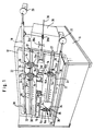
- Fig. 1 10 denotes a machine frame.
- This machine frame has a processing plate 12, on the front of which a plurality of processing units 14 are attached.
- These machining units 14 are intended and suitable for machining workpieces in a machining zone 16 from above and from below, possibly also with a machining direction directed obliquely against the vertical.
- Each processing unit consists of a base body 14a with a slide guide 14b, a guide slide 14c and a tool 14d.
- the processing units of each row of processing units are driven by a drive rod 18.
- the drive rods 18 are each driven by an oscillating drive 20 and linearly guided in a guide groove 22 of the processing plate 12.
- a control cam 24 is attached to the respective drive rod 18, which acts on the respective guide carriage 14c and in each case shifts it towards the processing zone 16, while the guide carriages are reset by a return spring 14e.
- the control cams 24 are attached to control cam elements 26, which are adjustable and lockable along the drive rods 18.
- the basic bodies 14a of the machining units 14 can be fixed in T-grooves 27 and in fields of fastening bores 28 by means of fastening pins, wherein positioning pins can also be inserted into the fastening bores 28, which also engage in bores of the basic bodies 14a. It is also conceivable to position the base body 14a on the processing plate 12 by intermeshing toothings and by additional fastening means which ensure the mutual engagement of the toothings.
- Positioning scales 30 are attached to the front plate, which allow the base bodies 14a to be readjusted into a list or computer position after removal from the processing plate 12 once, without the need for renewed empirical coordination.
- the control cam elements 26 can also be brought into reproducible positions on the respective drive rods by means of positioning scales 32. In addition, there is the possibility of removing and reinserting the drive rods together with the control cam elements 26 as complete structural units. It is thus possible to quickly convert the machine for various machining tasks by, on the one hand, exchanging the drive rods 18 with the control cam elements 26 attached to them as a whole and, on the other hand, the machining units 14 with the help of the positioning scales 30 into the positions corresponding to the respective machining task. In this case, the tools 14d can also remain on the guide carriage 14c if there are sufficient machining units available.
- the example is a punching and bending machine that produces 36 workpieces from a wire or strip material.
- the wire or strip material is drawn in by a drawing-in device 38 with a moving clamping point 38a and a stationary clamping point 38b.
- the stationary clamping point 38b is controlled by a control curve 24a of the drive rod 18. It is also conceivable to control the moving clamping point 38a from one of the drive rods 18.
- a slide 14c can also be guided directly on the processing plate, for example by strips 14x which are screwed onto the working plate 12 or are produced integrally with the working plate.
- a tool 14d is attached to the slide 14c. The tool 14d can also be guided directly in the strips 14x.
- the control cam element 26 is here, as shown in FIG. 1a, fastened to the drive rod 18, specifically clamped in a groove 18x by screws 18y.
- a fine toothing 18z positions the cam element 26 in the longitudinal direction of the drive rod 18 and transmits the longitudinal forces.
- the screws 18y pass through elongated holes in the cam elements 26, the length of which corresponds at least to the tooth pitch.
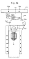
- a processing unit 14 is shown in detail in FIG. 2.
- One recognizes the base body 14a with the slide guide 14b, in which the guide slide 14c is guided.
- the guide carriage 14c is biased in the direction of the drive rod 18 by a spring, in particular a helical tension spring or a helical compression spring 14e.
- a pivot lever 14f is pivotably mounted on the base body 14a about a pivot pin 14g.
- This pivot lever 14g carries a cam follower roller 14h which is in engagement with a cam 24 of the cam element 26.
- a sliding shoe 14i is guided on the pivot lever 14f.
- This slide shoe 14i is pivotally connected to a hinge pin 14k by a connecting pin 14l.
- the hinge pin 14k engages with an external thread 14m adjustable in a threaded bore of a projection 14n of the guide carriage 14 c and is secured by locking nuts 14o.
- the sliding shoe 14i can be lifted off the pivot lever 14f. Any lift-off can be determined by a lift-off sensor 14p.
- FIG. 2a shows a modification compared to FIG. 2.
- the control cam element 126 is designed with two control cams 124a and 124b, and two cam follower rollers 114b1 and 114b2 are attached to the pivot lever 114f.
- at least the helical tension spring 14q of FIG. 2 can be omitted, but possibly also the helical tension spring 14e if the slide shoe 114i is connected to the pivoting lever 114f in a manner that prevents it from being lifted off.
- control cam element 26 or 126 is clamped to the drive rod 18 or 118, as indicated by clamping screws 26a or 126a.
- FIG. 2b differs from that according to FIG. 2 and according to FIG. 2a in particular in that two control cams 224a and 224b are attached to the pivot lever 214f, while two cam followers 214b1 and 214b2 are adjustable and fixable on the drive rod 218 Clamping screws 226a are attached.
- the drive rod 18 is most heavily loaded when it moves to the left and thereby pushes the guide carriage 14c downward, so that the tool attached to the guide carriage 14c performs a punching or bending operation. Accordingly, if possible, the rod 18 in FIG. 2 is operated to the left as a pull rod, so that no bending forces are introduced into the drive rod 18 which could lead to a load on the linear guide 22 (FIG. 1). If several processing units are connected to a drive rod, an attempt will be made to position the control cams in such a way that the greatest machining forces occur in the majority of processing units when the drive rod 18 is pulled by its drive (see 20 in FIG. 1). This will not be possible in all cases. Even if compressive forces occur in the drive rods, there is no danger of delay because the drive rods 18 are guided in the linear guides 22 over a substantial part of their length.
- FIG. 3 shows a machine frame, which is designated by 310 and has two main processing planes 312I, 312II.
- the machine frame 310 has a saddle 342, which has a cantilevered support part 344I and 344II above each of the main processing planes 312I and 312II having.
- a drive rod 318 can be seen in the projecting support part 344I, which has two longitudinal zones 318a and 318b next to one another for the attachment of control cam elements 326.
- the cam members 326 are engaged with guide carriages 314c to which machining tools 314d are attached.
- the guide carriages 314c can be driven in a similar manner to that shown in FIG. 2.
- the guide carriages 314c can be arranged one above the other in front of the main processing plane 312I, for example by being guided in a common base body 314a .
- one of the processing tools 314d is a hold-down device and the other is a bending or punching punch. In this way, which is desired, the holding-down device and the bending or punching stamp can be brought close to one another.
- each of the processing planes 312I and 312II can be assigned to two groups of processing units that work from above and below towards the processing zone 316.
- the machine frame 310 is penetrated by a passage 346 through which the workpieces to be machined can be transported between the two machining planes 312I and 312II.
- the transport can be carried out by a transport carriage 348 which reciprocates in the direction of the arrow 350 and has a driver 352.
- the transport carriage 348 can in turn be driven by a drive rod 354 with cam elements 356, which act on a cam follower 358 of the transport carriage 348.
- the transport carriage 348 is guided in a recessed guide groove 360 in the lower boundary surface of the passage 346.
- FIG. 3a A detail of FIG. 3 is shown in FIG. 3a.
- the drive rod 318 can be seen again.
- two clamping strips 317 are clamped, by means of a strip-shaped clamping piece 315.
- Each of the clamping strips 317 receives control cam elements 326 with control cams 324 in a clampable manner.
- the arrangement according to FIG. 4 corresponds essentially to that according to FIG. 3. Analogous parts are provided with the same reference numerals, each increased by the number 100.
- the control curve element of the longitudinal zone 418a on the drive rod 418 acts here on a guide slide 414c, which is a tool 414d
- the guide carriage is designed as shown in Fig. 2.
- the control cam element of the longitudinal zone 418b acts on a pivot lever 462, which in turn acts on a processing lever 466 via a connecting rod 464.
- This machining lever 466 is mounted at 468 on a support body 470 for the workpiece to be machined.
- the machining tool 414d and the machining lever 466 both act on the workpiece to be machined.
- a pivot lever 462 is shown schematically. It is pivotably mounted on a face 472 parallel to the main machining plane 412I in a joint 474 and, with its one arm 462a, picks up the control curve 424 of the drive rod 418, while it acts on the connecting rod 464 with its other lever arm 462b. It can be seen from the movement arrows that a downward movement of the lever arm 462a leads to an upward movement of the lever arm 462b. This inversion of the movement can be advantageous for various machining tasks.
- the cranks 462c and 462d can also be seen on the lever arms 462a and 462b. This offset enables the machining points for the workpiece to be shifted to different planes parallel to the main machining plane 412I, regardless of the position of the drive rod 418.
- a rod 462x is articulated to the lever 462 and is articulated to a guide slide 414c, the slide 414c being guided by strips 414x of the worktop 412.
- the guide strips 414x can be produced integrally with the working plate 412.
- a spring 414e holds the cam follower roller 414b in engagement with the guide curve 424.
- FIG. 6 shows another embodiment of the pivoting lever, which is designated 562 here.
- Analog parts are provided here with the same reference numerals as in Fig. 5, each increased by the number 100.
- the lever 562 is designed here as a one-sided lever, so that a downward movement of the lever arm 562a on the lever arm 562b also triggers a downward movement, as indicated by the directional arrows is indicated in Fig. 6.
- the cranks 562c and 562d also allow any offset of the control cam elements and the machining points with respect to the main machining plane 512I.
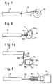
- FIG. 7 shows an eccentric drive for a drive rod 18.
- the drive rod 18 is connected to an eccentric bolt 80 of a drive pulley 82 via a connecting rod 78.
- the eccentric pin 80 is adjustable in the radial direction.
- the drive pulley 82 preferably rotates at a constant but variable speed.
- a cam disk 84 with a double cam 84a, 84b acts on a double cam follower with two cam follower rollers 86a and 86b, which is connected to the drive bar 18.
- different movements of the drive rod 18 can be achieved by appropriately selecting the curve shape of the curves 84a and 84b.
- the cam disk 84 preferably rotates around the axis of rotation 84c at a constant but variable speed.
- FIG. 8a corresponds in principle to that of FIG. 8, but between the cam followers 86a, 86b and the drive rod 18 there is still a transmission gear in the form of a lever 88, the pivot point 88a of which can be adjustable in the direction of the arrow 88b in order to increase the transmission ratio vary. In this way, the stroke of the drive rod 18 can be changed with the control cam 84 unchanged.
- the drive rod 18 is provided with a screw spindle 90 on which a ball nut 92 can be screwed.
- the ball nut 92 is connected to the output shaft 94 of a motor 96 which is reversibly driven.
- the motor can be a program-controlled motor, the direction of rotation, angular position and angular speed of which can be changed as a function of the program. In this way, the sequence of movements of the drive rod 18 can be varied as required by appropriate program selection and can be adjusted to the respective machining tasks.
- FIG. 10 shows two drive rods 18 which are driven by a common drive shaft 98.
- a transmission lever 97 is provided for each drive rod, which is pivotably mounted at 95.
- Each transmission lever 97 has two cam followers 93, 93 '.
- a cam disk 84 is provided on the drive shaft 98, only one cam disk 84 being shown.
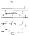
- control cams 24I, 24II and 24III attached to one and the same drive rod 18 are shown one above the other, together with the associated curve followers 14bI, 14bII and 14bIII. It can be seen that a different design and different phase shift between the associated guide carriages can be brought about by different design of the control cams 24I, 24II and 24III.
- the horizontal course of the individual control curves means that the associated guide carriage has come to a standstill. Only where the respective control curve deviates from the horizontal there is a movement of the associated guide carriage. So you can adjust the stroke of the drive rod 18 to the largest occurring stroke of a processing unit and win the smaller strokes of the other processing units by letting the control cams belonging to the latter run parallel to the drive rod 18 over a more or less large part of the length.
- FIG. 12 shows how a desired movement profile of a guide carriage 14c can be obtained from the movement profile of the drive rod 18 and the curve shape of a control cam 24.
- the quadrant I of FIG. 12 shows the course of movement of the drive rod 18 over time (or in other words: over the angular position of a central control shaft of the machine).
- the curve height of a curve 24 is plotted over the rod stroke.
- the course of movement of the guide carriage 14c is in turn plotted over time or over the control angle of the central control shaft.
- the points a - e in the individual curves only serve to show corresponding points of the individual curves in their mutual assignment. The following is important.
- Such extremely slow movements can thus be obtained in a simple manner by skillfully superimposing the movement profile of the movement curve of the drive rod 18 (Quadrant I) and the shape profile of the control curve 24 (Quadrant II).
- FIG. 13 shows a partial view of a modification compared to FIG. 3.
- the machine frame is designated 510 here and can be designed with a passage corresponding to passage 346 in FIG. 3.
- a main processing plane 544I can also be seen in FIG. 13.
- a further main processing level corresponding to processing level 344II of FIG. 3 can be provided.
- the drive rod 518 is guided here in the surface of the machine frame 510 parallel to the main processing plane 544.
- a finely toothed toothed rack 519 with two toothings 519a and 519b facing away from one another is attached to the drive rod 518.
- Control cam elements 526 which are provided with corresponding toothings, can be locked on each of these toothings 519a and 519b.
- the control elements 526 and 526a are held on drive rod 518 by fastening screws 527 and 527a, respectively.
- the cam 524 of the cam element 526 is in engagement with a cam follower roller 529 of a two-armed lever 531, which acts on a push rod 533.
- a processing unit 514 can be coupled to the lower end of the push rod 533.
- Another curve follower 529a is in engagement with the control curve 524a of the control curve element 526a.
- This cam follower 529a is in drive connection with a further machining element 514a via a push rod 533a.
- the two push rods 533 and 533a are arranged in different planes in front of the machine frame 510, so that, if desired, the two processing elements 514 and 514a can also be arranged one above the other in different processing planes. It is also essential that two cam followers 529 and 529a can be driven at the same location along the drive rod 518.
- the lever 531 is pivotally supported by a bearing pin 535 in one of several optionally available bearing bores.
- control cam elements 626 and 626a are locked here on toothings 619a and 619b of the drive rod 618 and by screws 627 attached to the mounting rod 619.
- the control cams 624 and 624a are both directed away from the machine frame 610.
- the cam follower 629a which is in engagement with the control cam 624a, is attached to a crank 637, which in a bearing 639 of the Machine frame 610 is pivotally mounted and moves a push rod 643 in a drawer 645 with a crank loop 641.
- a machining unit can be attached to the push rod 643, which works perpendicular to the machining plane 644I.
- a transport member can also be attached, which transports partially machined workpieces from one main processing level to another main processing level through a passage.
- the control cam 624 can serve for a similar drive.
- control cams 724x and 724y can be attached to one and the same control cam element 726, which can be used both in the arrangement according to FIG. 13 and in the arrangement according to FIG. 14, so that control cam element 726 from both a push rod corresponding to the push rod 533a of FIG. 13 and a crank corresponding to the crank 637 of FIG. 14 can be driven. It is possible to arrange two cam elements 726 one above the other, such as cam elements 526 and 526a in FIG. 13 and cam elements 626 and 626a in FIG. 14.
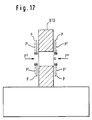
- FIG. 17 schematically shows a machine frame 810 corresponding to the machine frames 510 and 610 of FIGS. 13 and 14.
- the arrows P indicate different machining directions of machining units which can be driven, for example, by the control cams 524a of FIG. 13.
- the processing directions of processing units are indicated by the arrows P ', for example by the control curves 524 of FIG. 13 can be driven.
- Arrows P ′′ indicate the processing or transport directions of processing or transport members, which can be driven, for example, by the control cams 624a in FIG. 14.
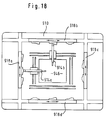
- FIG. 18 shows a machine frame 910 with a passage 946 in which the processing area is located.
- four drive rods 918a, 918b, 918c, 918d can each be displaced in the direction of the double arrow assigned to them around the passage 946. All of these rods are equipped with cam elements and serve to drive processing units 914a, 914b etc. All of these processing units work towards the central processing zone 946.
- two processing planes can be arranged on both sides of the machine frame 910, which are connected to one another by the passage 946. The same bar arrangement as in FIG. 18 can be made in the second processing plane, not shown.
- a control cam element 1026b which is designed in accordance with the control cam element 726 of FIG. 16, is also seated on the drive rod 1018.
- This control cam element 1026b drives the machining unit 1014b with a first control cam, which also acts on the workpieces 1049.
- a second control cam of the control cam element 1026b drives a further processing unit 1014c via a two-armed lever 1053.
- Corresponding processing units can be driven by the drive rod 1018 located on the right in FIG. 19.
- a drive unit 1057 is schematically indicated, which drives both the conveyor belt and the drive rods 1018 synchronously via schematically indicated transmission means 1059a, 1059b and 1059c.
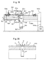
- FIG. 19 The arrangement of FIG. 19 can be seen schematically in FIG. 20.
- the arrows P represent the working movement of processing units 1014b.
- the arrows P ' represent the machining movement of machining units, not shown, in a higher machining plane, the latter machining units being able to be driven by a drive rod which have a second control surface, as shown in FIG. 3 at 318b.
- the arrow P ′′ represents the working movement of the processing unit 1014c 19.
- the arrow P ''' represents the working movement of the processing unit 1014a from FIG. 19, whereby, however, a change has been made compared to FIG. 19 in that the processing unit 1014a has been moved inside the conveyor belt loop 1045 so that the tool of the processing unit 1014a approaches the workpiece 1049 through openings in the conveyor belt.
- FIG. 21 shows a modification compared to FIG. 1.
- the drive rod 1118 is not guided in a guide groove here, but is guided by a plurality of guide links 1163 which are articulated with their upper ends on the machine frame 1110 and are articulated with their lower ends on the drive rod 1118.
- the drive rod 1118 is guided back and forth in the direction of the double arrow 1165 by drive means, as are shown, for example, in FIGS. 7-10.
- the control cam elements 1126 with the control cams 1124 are attached to the drive rod 1118, approximately in the manner described in FIG. 13 or 14.
- the control cams 1124 act on the machining units 1114, which are fastened in grooves 1127 and experience a tool movement that goes up and down in the direction of the arrow 1167.
- the longitudinal movement 1165 of the drive rod 1118 is superimposed by a slight vertical movement 1169.
- This vertical movement can be the design of the control curves 1124 are taken into account in such a way that the processing units 1114 carry out the correct movement again.
- the drive of the drive rod 1118 can be designed by a drive device, as shown in FIGS. 8, 8a, 9 or 10, in such a way that the movement in the direction of the arrow 1165a takes place with a greater movement speed of the rod 1118 than the movement in the direction of the arrow 1165b.
- a larger proportion of the time is then available for the working movement of the processing unit 1114 within the total time available for the outward and return stroke of the processing unit 1114. This can be advantageous because the necessary working stroke of the processing unit is then slower.
- the slower movement of the drive rod 1118a in the direction of the arrow 1165b is particularly advantageous when very steep flank regions occur at the control cam 1124, for example at 1124a.
- FIG. 22 shows a further modification to FIG. 1.
- a guide rail 1271 is guided by link 1263, so that there is again a horizontal movement 1265 and a small vertical movement 1269 of the guide rail 1271 when the guide rail 1271 is driven by a cam plate 1284 according to FIG. 8.
- a drive rod 1218 is also in the guide rail 1271
- Control cam elements 1226 driven by a cam drive 1284 '.
- the control cam elements 1226 act with their control cams 1224 on the processing unit 1214 in the manner already described.
- the basic movement of the drive rod 1218 is derived from the cam disc drive 1284 '.
- the cam mechanism 1284 can initiate the upward movement of the guide rail 1271 in the direction of the arrow 1269 when the drive rod 1218 has reached its end position in which the processing unit 1214 has finished its downward movement. At this moment, the guide rail 1271 is then lifted upwards, so that the machining units, without losing their engagement with the control cams 1224, immediately return upwards from their lowest working position. If the drive rod 1218 is then retracted again in the direction of the arrow 1265 into a position in which the downward movement of the machining units 1214 can begin again, the guide rail 1271 is lowered again by the cam disk drive 1284 by means of the link 1263. This mode of operation can be particularly advantageous if the working stroke of the drive rod 1218 is faster than the return stroke.
- FIG. 22 can also be realized by a modification according to FIG. 23.
- the guide rail 1371 is immovable in the horizontal direction and adjustable in the vertical direction by means of pneumatic or hydraulic cylinders 1373.
- the up and down movement 1369 is thus effected by the cylinders 1373.
- the embodiment according to FIG. 23 corresponds to that according to FIG. 22, analog parts being designated with the same reference numerals, each increased by the number 100.
- the drive rod 1418 can be composed of a plurality of drive rod sections 1418a, 1418b, 1418c and 1418d.
- the drive rod sections 1418a and 1418d are guided by a pair of links 1463a, 1463b, 1463c and 1463d, respectively.
- the individual sections 1418a-1418d are rigidly connected to one another in the direction of arrow 1465 by transmission elements 1477ab, 1477bc and 1477cd.
- the transmission elements permit a relative movement of the drive rod sections 1418a-1418d in the direction of the arrow 1469.
- the drive rod sections 1418a-1418d perform different strokes in the direction of the arrow 1469 during a movement cycle of the cam disk drive 1484 ′.
- a control cam element 1426b with a control cam 1424b of a straight and horizontal course is attached to the drive rod section 1418b.
- the working movement of the associated processing unit can be brought about solely by the vertical movement 1469 of the drive rod section 1418b, the stroke of which is determined by the length of the guide links 1463b.
- a control curve element 1426a with a conventional control curve 1424a is attached to the drive rod section 1418a, the control curve 1424a being selected such that its shape, taking into account the guide links 1463a, gives the desired course of movement of the associated processing unit (not shown).
- a control cam 1424c is attached to the drive rod section 1418c, the inclination of which can be varied with respect to the longitudinal direction of the drive rod section 1418c according to arrow 1479c. In this case leaves the respectively desired course of movement of the associated processing unit (not shown) is set by the choice of the angle of inclination of the control curve 1424c, taking into account the length of the guide links 1463c.
- the subdivision of the drive rod into individual sections can also be advantageous in the embodiment according to FIG. 1, namely when the drive rod becomes very long overall and is therefore difficult to machine.
- the individual drive rod sections can also be connected to one another in the embodiment according to FIG. 1 by transmission elements corresponding to the transmission elements 1477ab, 1477bc and 1477cd.
Landscapes
- Engineering & Computer Science (AREA)
- Mechanical Engineering (AREA)
- Press Drives And Press Lines (AREA)
- Wire Processing (AREA)
- Multi-Process Working Machines And Systems (AREA)
- Transmission Devices (AREA)
Description
Die Erfindung betrifft eine Bearbeitungsmaschine, insbesondere einen Stanz- und Biegeautomat, umfassend einen Maschinenrahmen mit einer Mehrzahl von Anbringungsstellen für Bearbeitungseinheiten und einem der Mehrzahl von Anbringungsstellen gemeinsamen Antriebsmittel zum Antrieb jeweils mindestens eines bewegten Teiles der jeweils angebrachten Bearbeitungseinheiten.The invention relates to a processing machine, in particular an automatic punching and bending machine, comprising a machine frame with a plurality of attachment points for processing units and a drive means common to the plurality of attachment points for driving at least one moving part of the respectively attached processing units.
Eine solche Bearbeitungsmaschine ist aus der deutschen Patentschrift 32 05 493 bekannt.Such a processing machine is known from
Bei der bekannten Bearbeitungsmaschine sind die Bearbeitungseinheiten an der Vorderseite einer Bearbeitungsplatte angeordnet. An der Rückseite der Bearbeitungsplatte ist eine Schneckenwelle parallel zu der Bearbeitungsplatte angeordnet. Die Bearbeitungseinheiten an der Vorderseite sind über die Länge der Schneckenwelle verteilt. In der Bearbeitungsplatte sind Bohrungen vorgesehen, durch welche hindurch Antriebswellen der einzelnen Bearbeitungseinheiten gesteckt werden, so daß Schneckenräder dieser Antriebswellen mit der Schneckenwelle in Eingriff gelangen. Diese bekannte Ausführungsform hat sich bewährt. Sie ist inbesondere für schnell laufende, hochpräzise Bearbeitungsmaschinen geeignet.In the known processing machine, the processing units are arranged on the front of a processing plate. On the back of the processing plate is one Worm shaft arranged parallel to the processing plate. The processing units on the front are distributed over the length of the worm shaft. Bores are provided in the machining plate, through which drive shafts of the individual machining units are inserted, so that worm gears of these drive shafts come into engagement with the worm shaft. This known embodiment has proven itself. It is particularly suitable for fast-running, high-precision processing machines.
Ein gewisser Nachteil der bekannten Bearbeitungsmaschine liegt darin, daß man durch die Bohrung der Löcher in der Bearbeitungsplatte den Ort der Bearbeitungseinheiten in Längsrichtung der Schneckenwelle weitgehend festgelegt hat, und daß im Rahmen dieser Festlegung eine weitere Anpassung des Orts der Bearbeitungseinheiten an den Ort einer bestimmten Bearbeitungsstelle eingeengt oder nur mit erheblichem Aufwand möglich ist.A certain disadvantage of the known processing machine lies in the fact that the location of the processing units in the longitudinal direction of the worm shaft has been largely determined by the drilling of the holes in the processing plate, and that within the scope of this definition a further adjustment of the location of the processing units to the location of a specific processing location is restricted or possible only with considerable effort.
Zum Stand der Technik gehört weiter eine Bearbeitungsmaschine, bei welcher an der Rückseite einer Bearbeitungsplatte ein Zahnriemen über Riemenscheiben geführt ist. Auch bei dieser Bearbeitungsmaschine sind die Bearbeitungseinheiten durch Löcher der Bearbeitungsplatte hindurch vermittels Antriebswellen angetrieben, welche über Zahnräder in den Zahnriemen eingreifen. Diese bekannte Bearbeitungsmaschine hat ersichtlich den gleichen Nachteil wie die oben erwähnte Bearbeitungsmaschine nach der DE-A-32 05 493, darüber hinaus aber noch zusätzlich den Nachteil, daß in dem Zahnriemen unvermeidbar Dehnungen infolge von Arbeitsbelastungen auftreten können, die zu einer unbeherrschbaren Phasenverschiebung des Laufs einzelner Bearbeitungseinheiten führen.The prior art also includes a processing machine in which a toothed belt is guided over pulleys on the back of a processing plate. In this processing machine, too, the processing units are driven through holes in the processing plate by means of drive shafts which engage the toothed belt via gearwheels. This known processing machine obviously has the same disadvantage as the processing machine according to DE-A-32 05 493 mentioned above, but additionally also the disadvantage that inevitable expansion can occur in the toothed belt due to workloads, which leads to an uncontrollable phase shift of the barrel individual processing units.
Der Erfindung liegt die Aufgabe zugrunde, eine Bearbeitungsmaschine der eingangs bezeichneten Art so auszubilden, daß die Ortsbindung der Bearbeitungseinheiten weitgehend vermieden ist und elastische Verformungen des Antriebsmittels unter Last ebenfalls weitestgehend vermieden sind.The invention has for its object to design a processing machine of the type mentioned in such a way that the location of the processing units is largely avoided is and elastic deformations of the drive means under load are also largely avoided.
Zur Lösung dieser Aufgabe wird bei der eingangs genannten Bearbeitungsmaschine erfindungsgemäß vorgeschlagen, daß das Antriebsmittel von mindestens einer an dem Maschinenrahmen in einer Führungsrichtung oszillierend hin- und herbeweglichen Antriebsstange gebildet ist, unddaß zur Antriebsübertragung von der Antriebsstangeneinheit zu Bearbeitungseinheiten jeweils eine Steuerkurven-Kurvenfolgerpaarung vorgesehen ist.To solve this problem, it is proposed according to the invention in the processing machine mentioned at the outset that the drive means is formed by at least one drive rod which oscillates back and forth on the machine frame in a guide direction, and that a control curve / cam follower pairing is provided in each case for drive transmission from the drive rod unit to processing units.
Bei der erfindungsgemäßen Lösung entfällt das Problem der Lagerung einer die Antriebseinheiten mit dem Antriebsmittel verbindenden Antriebswelle. Die Antriebsstange kann auf ihrer gesamten Länge oder auf dem größten Teil ihrer Länge in dem Maschinenrahmen geführt sein, so daß Biegekräfte auf die Antriebsstange keine Verformungen ausüben können. Eine Längsverformung der Antriebsstange unter Zug- und Druckkräften läßt sich durch entsprechende Querschnittsbemessung der Antriebsstange ohne weiteres vermeiden. Dabei empfiehlt es sich, die Bearbeitungseinheiten und den Antrieb der Antriebsstange so aufeinander abzustimmen, daß die höchsten Belastungen der Antriebsstange vorzugsweise dann auftreten, wenn die Antriebsstange durch den ihr vorgeschalteten Antrieb gezogen wird. Im Zugbetrieb ist nämlich die Gefahr einer Verformung der Antriebsstange geringer als im Schubbetrieb, so daß mit geringerer Lagerreibung in der Linearführung der Antriebsstange gerechnet werden kann. Außerdem ist im Zugbetrieb die Gefahr eines Ausknickens vermieden, die ihrerseits zu verstärkter Reibung in der Führung Anlaß geben könnte.In the solution according to the invention, the problem of mounting a drive shaft connecting the drive units to the drive means is eliminated. The drive rod can be guided over its entire length or over most of its length in the machine frame, so that bending forces cannot exert any deformation on the drive rod. A longitudinal deformation of the drive rod under tensile and compressive forces can easily be avoided by appropriate cross-sectional dimensioning of the drive rod. It is advisable to coordinate the processing units and the drive of the drive rod so that the highest loads on the drive rod preferably occur when the drive rod is pulled by the upstream drive. In traction operation, the risk of deformation of the drive rod is lower than in overrun operation, so that lower bearing friction in the linear guide of the drive rod can be expected. In addition, the risk of buckling is avoided in train operation, which in turn could give rise to increased friction in the guide.
Bei der erfindungsgemäßen Ausbildung läßt es sich ohne weiteres ermöglichen, die Antriebsstange und die Bearbeitungseinheiten auf ein und derselben Seite einer Bearbeitungsplatte anzuordnen, weil die Antriebsstange im Gegensatz zu einer Schneckenwelle oder einem Zahnriemen wenig Platz einnimmt und insbesondere die Führungsmittel für die Antriebsstange wenig Platz einnehmen. Man kann die Antriebsstange beispielsweise und vorzugsweise in einer Führungsnut einer Bearbeitungsplatte weitgehend versenkt führen. Befinden sich aber die Antriebsstange und die Antriebseinheit auf ein und derselben Seite einer Bearbeitungsplatte, so entfällt die Notwendigkeit, die Bearbeitungsplatte mit Bohrungen für die Durchführung der Antriebsleistung von der Antriebsstange zu den Bearbeitungseinheiten zu versehen, und damit entfällt auch die durch solche Bohrungen bedingte starre Positionierung der Bearbeitungseinheiten. Es wird vielmehr möglich, die Bearbeitungseinheiten kontinuierlich oder feinstufig längs der Antriebsstange zu verstellen und die Steuerkurven bzw. Kurvenfolger auf der Antriebsstange jeweils dort anzubringen, wo der von der Bearbeitungsaufgabe her optimale Ort für die Bearbeitungseinheit liegt. Selbstverständlich ist es bei einer solchen Lösung wie im Stand der Technik auch möglich, die Bearbeitungseinheiten unter einem von 90° verschiedenen Winkel gegenüber der Oszillationsrichtung der Antriebsstange an einer Bearbeitungsplatte anzubringen. Indes kann man auf die im Stand der Technik häufig angewandte Schrägstellung der Bearbeitungseinheiten zur Erreichung bestimmter Bearbeitungsorte bei der erfindungsgemäßen Lösung dann häufig verzichten, wenn die Schrägstellung nicht um der Bearbeitungsrichtung willen, sondern lediglich um der Wahl des Bearbeitungsorts willen in Betracht zu ziehen ist, weil bei der erfindungsgemäßen Lösung die Wahl des Bearbeitungsorts ohnehin durch kontinuierliche oder feinstufige Positionierung der Bearbeitungseinheiten möglich ist.In the embodiment according to the invention, it can be readily possible to arrange the drive rod and the processing units on one and the same side of a processing plate, because in contrast to a worm shaft or a toothed belt, the drive rod takes up little space and in particular the guide means for the drive rod take up little space. For example, the drive rod can preferably be largely sunk in a guide groove of a processing plate. However, if the drive rod and the drive unit are on one and the same side of a processing plate, there is no need to provide the processing plate with bores for carrying out the drive power from the drive rod to the processing units, and thus the rigid positioning caused by such bores is also eliminated the processing units. Rather, it becomes possible to continuously or finely adjust the processing units along the drive rod and to attach the control cams or cam followers on the drive rod in each case where the processing unit has the optimal location for the processing task. Of course, with such a solution as in the prior art, it is also possible to mount the processing units on a processing plate at an angle different from 90 ° with respect to the direction of oscillation of the drive rod. However, one can often do without the inclination of the processing units frequently used in the prior art to achieve certain processing locations in the solution according to the invention if the inclination is not to be taken into account for the processing direction but only for the selection of the processing location because in the solution according to the invention, the choice of the processing location is possible anyway through continuous or fine-step positioning of the processing units.
Die Positionierung der Bearbeitungseinheiten kann bei der erfindungsgemäßen Lösung durch Befestigungsnuten für die Bearbeitungseinheiten auf der jeweiligen Bearbeitungsplatte geschehen und/oder durch ein enges Feld von Positionierungsmitteln, etwa Positionierungsbohrungen oder Verzahnungen, die zur Aufnahme der Stangenkräfte geeignet sind. Eine Schrägstellung der Bearbeitungseinheiten soll bei der erfindungsgemäßen Lösung natürlich nicht ausgeschlossen sein.In the solution according to the invention, the machining units can be positioned by fastening grooves for the machining units on the respective machining plate and / or by a narrow field of positioning means, for example positioning bores or toothing, which are suitable for absorbing the rod forces. An inclination of the processing units should of course not be excluded in the solution according to the invention.
Die Steuerkurven können an der Antriebsstange einstückig mit dieser ausgebildet sein. Bevorzugt ist aber vorgesehen, daß die Steuerkurvenelemente bzw. Kurvenfolger an der jeweiligen Antriebsstange stufenlos oder feinstufig verstellbar und befestigbar sind, und daß die Bearbeitungseinheiten an dem Maschinenrahmen längs und gegebenenfalls quer zur jeweiligen Antriebsstange feinstufig oder kontinuierlich verstellbar und feststellbar sind.The control cams can be formed integrally with the drive rod. However, it is preferably provided that the control cam elements or cam followers are continuously or finely adjustable and attachable to the respective drive rod, and that the processing units on the machine frame are adjustable and ascertainable finely or continuously along and possibly transversely to the respective drive rod.
Die Oszillationsfrequenz und/oder der Oszillationshub und/oder der Oszillationsverlauf der Antriebsstange können veränderbar sein, um die verschiedensten Bearbeitungsaufgaben erfüllen zu können. Dies gilt insbesondere auch dann, wenn mehrere Antriebsstangen vorhanden sind, wobei dann entsprechende Veränderungen für jede einzelne dieser Antriebsstangen möglich sind.The oscillation frequency and / or the oscillation stroke and / or the oscillation profile of the drive rod can be changeable in order to be able to perform a wide variety of machining tasks. This also applies in particular if there are several drive rods, in which case corresponding changes are possible for each of these drive rods.
Für den Antrieb der Antriebsstangen stehen verschiedene Möglichkeiten zur Verfügung. So ist es möglich, daß die Antriebsstange durch einen Exzenterantrieb mit ggf. veränderlicher Exzentrizität und/oder veränderlicher Drehzahl angetrieben ist.Various options are available for driving the drive rods. So it is possible that the drive rod is driven by an eccentric drive with possibly variable eccentricity and / or variable speed.
Weiter ist es möglich, daß die Antriebsstange durch einen Kurventrieb angetrieben ist, wobei die Kurvenformen variabel sind. Durch die Überlagerung bestimmter Kurvenformen eines die Antriebsstange treibenden Kurventriebs und bestimmter Kurvenformen der an der Antriebsstange angebrachten oder an der jeweiligen Bearbeitungseinheit angebrachten Steuerkurvenelemente lassen sich interessante Bewegungsabläufe der Bearbeitungseinheit gewinnen, die bei einer Kurvenvariabilität an nur einer Stelle nicht ohne weiteres zur Verfügung stünden. Insbesondere lassen sich durch solche Überlagerung Bewegungsformen an der Bearbeitungseinheit gewinnen, die man mit einer einzigen herkömmlichen Sinuidkurve nicht erzielen kann, wohl aber durch Überlagerung zweier Sinuidkurven.It is also possible for the drive rod to be driven by a cam drive, the curve shapes being variable. By superimposing certain curve shapes of a cam drive driving the drive rod and certain curve shapes of the attached to or on the drive rod Control cam elements attached to the respective processing unit can be used to gain interesting movement sequences of the processing unit that would not be readily available at only one point if the curve was variable. In particular, such superimposition can be used to obtain forms of motion on the processing unit that cannot be achieved with a single conventional sinuid curve, but can be obtained by superimposing two sinuid curves.
Weiter ist es möglich, daß die Antriebsstange durch einen Spindeltrieb mit reversierendem Antriebsmotor angetrieben ist.It is also possible that the drive rod is driven by a spindle drive with a reversing drive motor.
Dabei kann der reversierende Antriebsmotor hinsichtlich seiner jeweiligen Einstellposition und/oder Einstellgeschwindigkeit programmgesteuert sein, so daß ähnliche Effekte erzielt werden können wie durch Variation einer Antriebskurve eines die Antriebsstange treibenden Kurventriebs.The reversing drive motor can be program-controlled with regard to its respective setting position and / or setting speed, so that similar effects can be achieved as by varying a drive curve of a cam drive driving the drive rod.
Die Antriebsstange kann weiterhin über ein Übersetzungsgetriebe mit variablem Übersetzungsverhältnis angetrieben sein, insbesondere über ein Hebelgetriebe mit variablem Übersetzungsverhältnis.The drive rod can also be driven via a transmission gear with a variable transmission ratio, in particular via a lever gear with a variable transmission ratio.
Der Begriff "Bearbeitungseinheiten" ist im weitestens Sinn zu verstehen und umfaßt beispielsweise auch Baugruppen an einer Montagemaschine oder an einer Verpackungsmaschine. Darüber hinaus kann auch der Antrieb von Zusatzeinrichtungen einer Bearbeitungsmaschine von einer Antriebsstange abgeleitet sein, z. B. der Antrieb von Materialeinzugsvorrichtungen und/oder Werkstück-Transporteinrichtungen.The term “processing units” is to be understood in the broadest sense and also includes, for example, assemblies on an assembly machine or on a packaging machine. In addition, the drive of additional devices of a processing machine can be derived from a drive rod, for. B. the drive of material feeders and / or workpiece transport devices.
Bei Vorhandensein mehrerer Antriebsstangen besteht die Möglichkeit, diese von einer gemeinsamen Antriebswelle her anzutreiben, ggf. über verschiedene übersetzungsvariable Übersetzungsgetriebe.If there are several drive rods, it is possible to drive them from a common drive shaft, possibly via different transmission gears with variable transmission ratios.
Die Erfindung läßt sich mit unterschiedlichsten Formen von Maschinenrahmen verwirklichen. So ist es beispielsweise möglich, daß an einer Hauptarbeitsebene des Maschinenrahmens zwei zueinander im wesentlichen parallel verlaufende Antriebsstangen angeordnet sind, daß zwischen diesen Antriebsstangen eine Werkstückbearbeitungszone vorgesenen ist, und daß jeder Antriebsstange Bearbeitungseinheiten zugeordnet sind, deren bewegte Teile jeweils annähernd in Richtung auf die Bearbeitungszone hin und zurück beweglich sind.The invention can be implemented with a wide variety of forms of machine frames. So it is possible, for example, that two essentially parallel drive rods are arranged on a main working plane of the machine frame, that a workpiece machining zone is provided between these drive rods, and that each drive rod is assigned machining units, the moving parts of which are each approximately in the direction of the machining zone and are moving back.
Weiter ist es möglich, daß an dem Maschinenrahmen zwei zueinander im wesentlichen parallele, voneinander beabstandete Bearbeitungsebenen ausgebildet sind, daß jeder dieser Bearbeitungsebenen mindestens eine Antriebsstange zugeordnet ist, wobei diese Antriebsstangen im wesentlichen zueinander parallel sind, und daß der Maschinenrahmen einen, die beiden Bearbeitungsebenen miteinander verbindenden Werkstückdurchgang aufweist. Bei dieser letzteren Ausführungsform können Werkstücke beispielsweise zuerst an einer ersten Bearbeitungsebene bearbeitet werden, dann durch den Werkstückdurchgang hindurch zur zweiten Bearbeitungsebene transportiert werden und dann an der zweiten Bearbeitungsebene bearbeitet werden, wobei auch der Begriff "Bearbeitung" hier wieder in dem oben definierten weiten Sinn zu verstehen ist.It is further possible that two mutually substantially parallel, spaced apart machining planes are formed on the machine frame, that at least one drive rod is assigned to each of these machining planes, these drive rods being essentially parallel to one another, and that the machine frame one, the two machining planes with one another connecting workpiece passage. In this latter embodiment, workpieces can, for example, be processed first on a first processing level, then transported through the workpiece passage to the second processing level and then processed on the second processing level, the term "processing" also being used here again in the broad sense defined above understand is.
Ist ein Durchgang zwischen zwei Bearbeitungsebenen vorhanden, so ist es möglich, daß in dem Durchgang Quertransportmittel vorgesehen sind, um Werkstücke von der einen zur anderen Bearbeitungsebene zu übergeben, wobei diese Transportmittel vorzugsweise durch eine in ihrer Längsrichtung oszillierende Antriebsstange angetrieben sind.If there is a passage between two processing planes, it is possible that transverse transport means are provided in the passage in order to transfer workpieces from one processing plane to the other, these transport means preferably being driven by a drive rod which oscillates in their longitudinal direction.
Eine weitere Möglichkeit zur Durchführung unterschiedlicher Bearbeitungen besteht darin, daß vor einer Bearbeitungsebene in Richtung senkrecht zur Bearbeitungsebene mehrere, insbesondere zwei zueinander parallele Antriebsstangen nebeneinander angeordnet sind. Bei einer solchen Ausbildung lassen sich aufeinander folgende Bearbeitungseinheiten bis auf kleinsten Abstand aneinander heranbringen und u. U. auch übereinander oder mit Überlappung anordnen, da die Längserstreckung der Steuerkurven nicht mehr bestimmend für den Abstand benachbarter Bearbeitungseinheiten ist. Auf diese Weise lassen sich beispielsweise Niederhalter und Bearbeitungswerkzeuge an Draht- und Bandbiegemaschinen auf engstem Raum ohne Schwierigkeiten unterbringen. Die Verwendung zweier zueinander paralleler, einzeln angetriebener Antriebsstangen bietet dabei den Vorteil, daß diese unterschiedlichen Hub und unterschiedliche Oszillationsfrequenz haben und unterschiedliche Bewegungsabläufe ausführen können. Der Vorteil größter Anhäherung und ggf` Überlappung benachbarter Bearbeitungseinheiten läßt sich auch dadurch erzielen, daß vor einer Bearbeitungsebene des Maschinenrahmens eine Antriebsstange angeordnet ist, welche zwei senkrecht zur Bearbeitungsebene nebeneinander liegende Längszonen für die Ausbildung von Steuerkurven oder Anbringung von Steuerkurvenelementen aufweist, wobei dann allerdings die Möglichkeit unterschiedlicher Bewegungsabläufe der einzelnen Längszonen nicht besteht. Die Antriebsstange bzw. -stangen können zur Antriebsvermittlung auf die an einer Bearbeitungsebene angebrachten Bearbeitungseinheiten mit Vorteil auch an einem über die Bearbeitungsebene nach vorn auskragenden Trägerteil des Maschinenrahmens angeordnet sein. Dabei bietet sich auch die Möglichkeit an, daß an einer zur Bearbeitungsebene im wesentlichen parallelen Stirnfläche des Trägerteils Lagerungsmöglichkeiten für Umlenkhebel angebracht sind, welche einerseits mit jeweils einer Steuerkurve an einer Antriebsstange in Eingriff stehen und andererseits auf einen bewegten Teil einer Bearbeitungseinheit einwirken.A further possibility for carrying out different machining operations is that several, in particular, in front of one machining plane in the direction perpendicular to the machining plane two mutually parallel drive rods are arranged side by side. With such a design, successive processing units can be brought close to one another and u. U. Arrange one above the other or with an overlap, since the longitudinal extent of the control curves is no longer decisive for the distance between adjacent processing units. In this way, hold-down devices and processing tools on wire and strip bending machines, for example, can be accommodated in a confined space without difficulty. The use of two mutually parallel, individually driven drive rods offers the advantage that they have different strokes and different oscillation frequencies and can carry out different movements. The advantage of maximum approximation and, if necessary, overlapping of adjacent processing units can also be achieved by arranging a drive rod in front of a processing plane of the machine frame, which has two longitudinal zones lying next to one another perpendicular to the processing plane for the formation of control cams or attachment of control curve elements, but then the There is no possibility of different movements of the individual longitudinal zones. The drive rod or rods can advantageously also be arranged on a machining part of the machine frame which projects forward over the machining plane in order to mediate the drive on the machining units attached to a machining plane. There is also the possibility that mounting options for deflecting levers are attached to an end face of the carrier part that is essentially parallel to the working plane, which, on the one hand, engages with a control cam on a drive rod and, on the other hand, act on a moving part of a processing unit.
Bei der erfindungsgemäßen Ausbildung ist es denkbar, den bewegten Teil einer Bearbeitungseinheit unmittelbar mit einem Kurvenfolger auszuführen, der mit einem Steuerkurvenelement einer Antriebsstange in Eingriff steht oder umgekehrt. Es ist aber auch möglich, daß der bewegte Teil einer Bearbeitungseinheit von einem Schlitten gebildet ist, welcher an einer Schlittenführung der Bearbeitungseinheit linear und insbesondere annähernd senkrecht zur Längserstreckung der Antriebsstange geführt ist, und daß dieser Schlitten in Antriebsverbindung mit einem an der Schlittenführung oder an dem Maschinenrahmen schwenkbar gelagerten Schwenkhebel steht, der eine Schwenkbewegung von einer Antriebsstange erhält und auf den Schlitten überträgt. Bei dieser Ausführungsform werden Querkräfte auf die Schlittenführung weitgehend vermieden. Die beim Zusammenwirken von Steuerkurve und Kurvenfolger auftretenden Querkräfte werden dann nämlich durch die Lagerung des Schwenkhebels aufgenommen. Dieser Schwenkhebel sollte sich im wesentlichen quer zur Bewegungsrichtung des Schlittens und parallel zur Bewegungsrichtung der Antriebsstange erstrecken. Besonders günstige Belastungsverhältnisse ergeben sich dabei dann, wenn eine Eingriffstelle zwischen dem Schwenkhebei und der Antriebsstange und eine Eingriffstelle zwischen dem Schwenkhebel und dem Schlitten annähernd in Flucht miteinander liegen mit einer zur Bewegungsrichtung des Schlittens im wesentlichen parallelen Fluchtrichtung.In the configuration according to the invention, it is conceivable to directly move the moving part of a processing unit with a Execute curve follower, which is in engagement with a cam element of a drive rod or vice versa. However, it is also possible that the moving part of a processing unit is formed by a carriage which is guided linearly on a carriage guide of the processing unit and in particular approximately perpendicular to the longitudinal extension of the drive rod, and that this carriage is in drive connection with one on the carriage guide or on the Machine frame is pivotally mounted pivoting lever that receives a pivoting movement from a drive rod and transfers it to the slide. In this embodiment, lateral forces on the slide guide are largely avoided. The transverse forces that occur when the control cam and cam follower interact are then absorbed by the bearing of the swivel lever. This pivot lever should extend essentially transversely to the direction of movement of the slide and parallel to the direction of movement of the drive rod. Particularly favorable load conditions arise when an engagement point between the pivoting lever and the drive rod and an engagement point between the pivoting lever and the slide are approximately in alignment with one another with an escape direction essentially parallel to the direction of movement of the slide.
Bei verschiedenen Bearbeitungsmaschinen, z. B. bei Stanz- und Biegemaschinen, besteht gelegentlich die Gefahr, daß ein bewegtes Werkzeug an der Bearbeitungsstelle klemmt und nicht zurückgezogen werden kann. Hier läßt sich bei Vorhandensein eines Schwenkhebels dadurch Vorsorge treffen, daß eine Eingriffsverbindung zwischen dem Schwenkhebel und dem Schlitten durch eine den Schlitten gegen den Schwenkhebel vorspannende Federkraft hergestellt ist, und daß an der Stelle dieser Eingriffsverbindung ein Sensor vorgesehen ist, welcher eine etwaige Trennung zwischen dem Schlitten und dem Schwenkhebel feststellt und bei Feststellung einer solchen Trennung ein Stillstandsignal für die Bearbeitungsmaschine liefert.With different processing machines, e.g. B. in punching and bending machines, there is occasionally the risk that a moving tool jams at the processing point and can not be withdrawn. Here, in the presence of a pivot lever, precautionary measures can be taken to ensure that an engagement connection between the pivot lever and the slide is produced by a spring force which prestresses the slide against the pivot lever, and that a sensor is provided at the location of this engagement connection, which detects any separation between the Detects carriage and the pivot lever and delivers a standstill signal for the processing machine when such separation is detected.
Einfache Bearbeitungsvorgänge lassen sich häufig auch durch geradlinige Steuerkurven ausführen. Insbesondere gilt dies dann, wenn die Möglichkeit besteht, den Winkel der geradlinigen Steuerkurven gegenüber der Oszillationsrichtung der Antriebsstange zu verändern. Es wird deshalb weiter vorgeschlagen, daß ein Steuerkurvenelement eine geradlinige Steuerkurve aufweist und daß die Winkeleinstellung dieser Steuerkurve relativ zur Oszillationsrichtung der Antriebsstange veränderbar und feststellbar ist.Simple machining processes can often also be carried out using straight-line control curves. This applies in particular when it is possible to change the angle of the straight control cams with respect to the direction of oscillation of the drive rod. It is therefore further proposed that a control cam element has a rectilinear control cam and that the angle setting of this control cam can be changed and ascertained relative to the direction of oscillation of the drive rod.
Ein häufiges Problem an Bearbeitungsmaschinen ist es, mit kurzen Umrüstzeiten eine Umrüstung für verschiedene Bearbeitungsaufgaben vorzunehmen. Für die Lösung dieses Problems ist die erfindungsgemäße Bearbeitungsmaschine besonders geeignet oder jedenfalls leicht geeignet zu machen, und zwar dadurch, daß die Antriebsstange mit an ihr angebrachten Steuerkurven bzw. Steuerkurvenelementen als ganze betriebsmäßig austauschbar ist, daß Positionsaufzeichnungsmittel vorgesehen sind, um bestimmte, einmal einjustierte Positionen der Bearbeitungseinheiten aufzuzeichnen, und daß an der Bearbeitungsmaschine Positionsanzeigemittel vorgesehen sind, welche es gestatten, eine aus einer einmal einjustierten Position entnommene Bearbeitungseinheit zu einem späteren Zeitpunkt mit Hilfe der Positionsaufzeichnung wieder in der einjustierten Stellung an der Bearbeitungsnaschine anzubringen.A common problem with processing machines is to carry out a conversion for different processing tasks with short changeover times. To solve this problem, the processing machine according to the invention is particularly suitable or at least easily made suitable, namely in that the drive rod with control cams or control cam elements attached to it as a whole is operationally interchangeable, that position recording means are provided for specific, once adjusted positions of the processing units, and that position display means are provided on the processing machine which allow a processing unit removed from a once-adjusted position to be attached to the processing machine at a later point in time using the position recording.
Um für den Bearbeitungshub der Bearbeitungseinheiten einen möglichst großen Anteil der für einen Bearbeitungszyklus der Bearbeitungseinheiten insgesamt zur Verfügung stehenden Zeit verfügbar zu machen, wird vorgeschlagen, daß eine Antriebsstangeneinheit in einer Bewegungsrichtung, die dem Arbeitshub zugehöriger Bearbeitungseinheiten entspricht, langsamer angetrieben ist als in einer Bewegungsrichtung, die dem Rückhub der zugehörigen Bearbeitungseinheiten entspricht.In order to make as large as possible a portion of the total time available for a machining cycle of the machining units for the machining stroke of the machining units, it is proposed that a drive rod unit be driven more slowly in a direction of movement that corresponds to the machining stroke of associated machining units than in a direction of movement, which corresponds to the return stroke of the associated processing units.
Um eine Antriebsstangeneinheit, die sich über eine große Länge erstreckt, leichter herstellen zu können, wird vorgeschlagen, daß eine Antriebsstangeneinheit aus einer Mehrzahl von miteinander im wesentlichen fluchtenden Antriebsstangenabschnitten besteht, die in Längsrichtung der Antriebsstangeneinheiten zur gemeinsamen Bewegung verbunden sind. Dies eröffnet auch die Möglichkeit, einzelnen Abschnitten der Antriebsstangeneinheit unterschiedliche Querbewegungen quer zur Längserstreckung der Antriebsstangeneinheit erteilen zu können.In order to be able to manufacture a drive rod unit that extends over a long length more easily, it is proposed that a drive rod unit consist of a plurality of substantially aligned drive rod sections that are connected in the longitudinal direction of the drive rod units for common movement. This also opens up the possibility of being able to impart different transverse movements transverse to the longitudinal extension of the drive rod unit to individual sections of the drive rod unit.
Um eine leicht herzustellende Führung für eine Antriebsstangeneinheit oder einen Teil davon zu ermöglichen, wird vorgeschlagen, daß mindestens ein Abschnitt einer Antriebsstangeneinheit durch Führungslenker nach Art eines Gelenkparallelogramms geführt ist. Diese Art der Führung ergibt zwangsläufig eine gewisse Querbewegung des jeweiligen Antriebsstangenabschnitts. Diese Querbewegung kann gegebenenfalls allein zur Gewinnung des Arbeitshubs zugehöriger Bearbeitungseinheiten herangezogen werden, indem man die zugehörigen Steuerkurven linear und parallel zu der Längsbewegung der Antriebsstangeneinheit ausbildet. Es ist aber auch möglich, die Steuerkurven mit beliebigem nichtlinearem Profil auszuführen und bei der Profilberechnung die Querbewegung des Steuerstangenabschnitts so zu berücksichtigen, daß sich der gewünschte Bewegungsverlauf der Bearbeitungseinheiten ergibt.In order to enable an easily produced guide for a drive rod unit or a part thereof, it is proposed that at least a section of a drive rod unit is guided by guide links in the manner of a joint parallelogram. This type of guidance inevitably results in a certain transverse movement of the respective drive rod section. This transverse movement can optionally be used solely to obtain the working stroke of associated processing units by forming the associated control cams linearly and parallel to the longitudinal movement of the drive rod unit. However, it is also possible to carry out the control curves with any non-linear profile and to take the transverse movement of the control rod section into account in the profile calculation in such a way that the desired course of movement of the processing units is obtained.
Um eine Bearbeitung mit einer größeren Anzahl von Bearbeitungsrichtungen zu ermöglichen, wird vorgeschlagen, daß in mindestens einer Bearbeitungsebene eine Mehrzahl von Antriebsstangeneinheiten längs eines Polygons angeordnet sind, das eine Bearbeitungszone umgibt.In order to enable machining with a larger number of machining directions, it is proposed that a plurality of drive rod units be arranged in at least one machining plane along a polygon which surrounds a machining zone.
Um die Bearbeitungsmaschine für Montagezwecke geeignet zu machen, empfiehlt es sich, daß wenigstens ein Teil der Bearbeitungseinheiten und die zugehörigen Antriebsstangeneinheiten in einer horizontalen Bearbeitungsebene angeordnet sind.In order to make the processing machine suitable for assembly purposes, it is recommended that at least some of the processing units and the associated drive rod units are arranged in a horizontal processing plane.
Um die Werkstücke auch dann, wenn sie nicht draht- oder bandartig zusammenhängen, durch verschiedene Bearbeitungsstationen transportieren zu können, wird vorgeschlagen, daß an dem Maschinenrahmen ein Transportmittel vorgesehen ist, um zu bearbeitende Werkstücke schrittweise durch verschiedene Bearbeitungsstationen zu transportieren.In order to be able to transport the workpieces through different processing stations even if they are not connected in a wire or belt-like manner, it is proposed that a transport means be provided on the machine frame in order to transport the workpieces to be processed step by step through different processing stations.
Die beiliegenden Figuren erläutern die Erfindung anhand von Ausführungsbeispielen. Es stellen dar:
- Fig. 1
- eine Frontalansicht einer erfindungsgemäßen Bearbeitungsmaschine;
- Fig. 1a
- ein Detail bei Ia der Fig. 1;
- Fig. 2
- eine Bearbeitungseinheit an einer erfindungsgemäßen Bearbeitungsmaschine;
- Fig. 2a
- eine erste Abwandlung zu Fig. 2;
- Fig. 2b
- eine weitere Abwandlung zu Fig. 2;
- Fig. 3
- eine weitere Ausführungsform einer erfindungsgemäßen Bearbeitungsmaschine;
- Fig. 3a
- die Antriebsstangen an der Bearbeitungsmaschine gemäß Fig. 3;
- Fig. 4.
- eine Abwandlung zu Fig. 3;
- Fig. 5
- ein perspektivisches Schema zu der Fig. 4;
- Fig. 5a
- eine Frontansicht zu Fig. 5;
- Fig. 6
- eine Abwandlung zu Fig. 5;
- Fig. 7, 8, 8a und 9
- verschiedene Antriebsmöglichkeiten für eine Antriebsstange;
- Fig. 10
- das Schema eines mehreren Antriebsstangen gemeinsamen Antriebs;
- Fig. 11
- ein Schema zur Erläuterung einer Betriebsphasenverschiebung für mehrere Bearbeitungseinheiten;
- Fig. 12
- eine Ableitung des Bewegungsverlaufs einer Bearbeitungseinheit aus dem Bewegungsverlauf einer Antriebsstange und der Form einer Steuerkurve;
- Fig. 13
- eine Abwandlung zu Fig. 3, bei welcher an einer Antriebsstange an zwei entgegengerichteten Seitenflächen Steuerkurvenelemente angebracht sind;
- Fig. 14
- eine weitere Abwandlung zu Fig. 3, bei welcher an einer Antriebsstange in Abstand voneinander Steuerkurvenelemente angebracht sind, deren Steuerkurven von der jeweiligen Bearbeitungsebene wegweisen;
- Fig. 15
- eine konkrete Ausführungsform der in Fig. 14 schematisch dargestellten Hebelanordnung;
- Fig. 16
- ein Steuerkurvenelement mit zwei in verschiedenen Ebenen liegenden Steuerkurven zum Anbau bei einer Anordnung nach Fig. 14;
- Fig. 17
- ein Bearbeitungsschema an einer erfindungsgemäßen Bearbeitungsmaschine;
- Fig. 18
- eine erfindungsgemäße Bearbeitungsmaschine mit in rechteckiger Zuordnung verlaufenden Antriebsstangen;
- Fig. 19
- eine Bearbeitungsmaschine mit horizontal liegender Hauptbearbeitungsebene und einer Werkstück-Transporteinrichtung;
- Fig. 20
- ein Bearbeitungsschema zu Fig. 19;
- Fig. 21
- eine Ausführungsform mit abgewandelter Antriebsstangenführung;
- Fig. 22
- eine Ausführungsform mit einer weiteren abgewandelten Antriebsstangenführung;
- Fig. 23
- eine Ausführungsform mit einer weiteren abgewandelten Antriebsstangenführung und
- Fig. 24
- eine Ausführungsform mit einer weiteren abgewandelten Antriebsstangenführung.
- Fig. 1
- a front view of a processing machine according to the invention;
- Fig. 1a
- a detail at Ia of Fig. 1;
- Fig. 2
- a processing unit on a processing machine according to the invention;
- Fig. 2a
- a first modification to Fig. 2;
- Fig. 2b
- a further modification to Fig. 2;
- Fig. 3
- a further embodiment of a processing machine according to the invention;
- Fig. 3a
- the drive rods on the processing machine shown in FIG. 3;
- Fig. 4.
- a modification to Fig. 3;
- Fig. 5
- a perspective diagram of FIG. 4;
- Fig. 5a
- a front view of Fig. 5;
- Fig. 6
- a modification to Fig. 5;
- 7, 8, 8a and 9
- different drive options for a drive rod;
- Fig. 10
- the diagram of a drive common to several drive rods;
- Fig. 11
- a diagram for explaining an operating phase shift for several processing units;
- Fig. 12
- deriving the course of movement of a processing unit from the course of movement of a drive rod and the shape of a control curve;
- Fig. 13
- a modification to Figure 3, in which control elements are attached to a drive rod on two opposite side surfaces.
- Fig. 14
- a further modification to FIG. 3, in which control cam elements are mounted on a drive rod at a distance from one another, the control cams of which point away from the respective working plane;
- Fig. 15
- a concrete embodiment of the lever arrangement shown schematically in Fig. 14;
- Fig. 16
- a control cam element with two control cams lying in different planes for mounting in an arrangement according to FIG. 14;
- Fig. 17
- a machining scheme on a machine tool according to the invention;
- Fig. 18
- a processing machine according to the invention with drive rods running in a rectangular assignment;
- Fig. 19
- a processing machine with a horizontal main processing plane and a workpiece transport device;
- Fig. 20
- a processing scheme for Fig. 19;
- Fig. 21
- an embodiment with a modified drive rod guide;
- Fig. 22
- an embodiment with a further modified drive rod guide;
- Fig. 23
- an embodiment with a further modified drive rod guide and
- Fig. 24
- an embodiment with a further modified drive rod guide.
In Fig. 1 ist mit 10 ein Maschinenrahmen bezeichnet. Dieser Maschinenrahmen besitzt eine Bearbeitungsplatte 12, an deren Vorderseite eine Mehrzahl von Bearbeitungseinheiten 14 angebracht sind. Diese Bearbeitungseinheiten 14 sind dazu bestimmt und geeignet, Werkstücke in einer Bearbeitungszone 16 von oben her und von unten her zu bearbeiten, ggf. auch mit schräg gegen die Vertikale gerichteter Bearbeitungsrichtung.In Fig. 1, 10 denotes a machine frame. This machine frame has a
Jede Bearbeitungseinheit besteht aus einem Grundkörper 14a mit einer Schlittenführung 14b, einem Führungsschlitten 14c und einem Werkzeug 14d. Die Bearbeitungseinheiten jeweils einer Reihe von Bearbeitungseinheiten sind durch eine Antriebsstange 18 angetrieben. Die Antriebsstangen 18 sind durch je einen oszillierenden Antrieb 20 angetrieben und in jeweils einer Führungsnut 22 der Bearbeitungsplatte 12 linear geführt. Für jede Bearbeitungseinheit ist an der jeweiligen Antriebsstange 18 eine Steuerkurve 24 angebracht, die auf den jeweiligen Führungsschlitten 14c einwirkt und diese jeweils zur Bearbeitungszone 16 hin verschiebt, während die Rückstellung der Führungsschlitten jeweils durch eine Rückstellfeder 14e geschieht.Each processing unit consists of a
Die Steuerkurven 24 sind an Steuerkurvenelementen 26 angebracht, welche längs der Antriebsstangen 18 verstellbar und feststellbar sind. Die Grundkörper 14a der Bearbeitungseinheiten 14 sind in T-Nuten 27 und in Feldern von Befestigungsbohrungen 28 mittels Befestigungsstiften feststellbar, wobei in die Befestigungsbohrungen 28 Positionierungsstifte eingeführt werden können, die auch in Bohrungen der Grundkörper 14a eingreifen. Auch ist es denkbar, die Grundkörper 14a an der Bearbeitungsplatte 12 durch ineinander greifende Verzahnungen und durch zusätzliche Befestigungsmittel zu positionieren, welche den gegenseitigen Eingriff der Verzahnungen sichern. An der Frontplatte sind Positionierungsskalen 30 angebracht, welche es gestatten, die Grundkörper 14a nach einmal erfolgter Abnahme von der Bearbeitungsplatte 12 in eine listenmäßig oder computermäßig erfaßte Position wieder einzustellen, ohne daß eine erneute empirische Abstimmung stattfinden muß. Auch die Steuerkurvenelemente 26 können durch Positionierungsskalen 32 in reproduzierbare Positionen auf den jeweiligen Antriebsstangen gebracht werden. Darüber hinaus besteht die Möglichkeit, die Antriebsstangen zusammen mit den Steuerkurvenelementen 26 als komplette Baueinheiten zu entnehmen und wieder einzusetzen. Somit ist es möglich, die Maschine für verschiedene Bearbeitungsaufgaben rasch umzurüsten, indem man einerseits die Antriebsstangen 18 mit daran befestigten Steuerkurvenelementen 26 als ganze austauscht und andererseits die Bearbeitungseinheiten 14 mit Hilfe der Positionierungsskalen 30 in die der jeweiligen Bearbeitungsaufgabe entsprechenden Positionen bringt. Dabei können auch die Werkzeuge 14d jeweils an dem Führungschlitten 14c verbleiben, wenn Bearbeitungseinheiten in ausreichender Zahl zur Verfügung stehen.The
Im Beispielsfall handelt es sich um einen Stanz-Biege-Automaten, der aus einem Draht- oder Bandmaterial 36 Werkstücke herstellt. Der Einzug des Draht- oder Bandmaterials erfolgt durch eine Einzugsvorrichtung 38 mit einer bewegten Klemmstelle 38a und einer stationären Klemmstelle 38b. Im Beispielsfall ist die stationäre Klemmstelle 38b durch eine Steuerkurve 24a der Antriebsstange 18 gesteuert. Denkbar ist es auch, die bewegte Klemmstelle 38a von einer der Antriebsstangen 18 her zu steuern.In the example, it is a punching and bending machine that produces 36 workpieces from a wire or strip material. The wire or strip material is drawn in by a drawing-in
In Fig. 1 ist bei Ia angedeutet, daß ein Schlitten 14c auch unmittelbar an der Bearbeitungsplatte geführt sein kann, etwa durch Leisten 14x, welche auf die Arbeitsplatte 12 aufgeschraubt oder integral mit der Arbeitsplatte hergestellt sind. An dem Schlitten 14c ist ein Werkzeug 14d befestigt. Es kann auch das Werkzeug 14d unmittelbar in den Leisten 14x geführt sein.In Fig. 1 it is indicated at Ia that a
Das Steuerkurvenelement 26 ist hier, wie in Fig. 1a gezeigt, an der Antriebsstange 18 befestigt, und zwar in einer Nut 18x durch Schrauben 18y festgeklemmt. Eine Feinverzahnung 18z positioniert das Steuerkurvenelement 26 in Längsrichtung der Antriebsstange 18 und überträgt die Längskräfte. Die Schrauben 18y durchgreifen Langlöcher der Steuerkurvenelemente 26, deren Länge mindestens der Zahnteilung entspricht.The
In Fig. 2 ist eine Bearbeitungseinheit 14 im einzelnen dargestellt. Man erkennt den Grundkörper 14a mit der Schlittenführung 14b, in welcher der Führungsschlitten 14c geführt ist. Der Führungsschlitten 14c ist durch eine Feder, insbesondere eine Schraubenzugfeder oder eine Schraubendruckfeder 14e in Richtung auf die Antriebsstange 18 vorgespannt. An dem Grundkörper 14a ist ein Schwenkhebel 14f um einen Schwenkbolzen 14g schwenkbar gelagert. Dieser Schwenkhebel 14g trägt eine Kurvenfolgerrolle 14h, welche mit einer Steuerkurve 24 des Steuerkurvenelements 26 in Eingriff steht. An dem Schwenkhebel 14f ist ein Gleitschuh 14i geführt. Dieser Gleitschuh 14i ist mit einem Gelenkbolzen 14k durch einen Verbindungsbolzen 14l schwenkbar verbunden. Der Gelenkbolzen 14k greift mit einem Außengewinde 14m einstellbar in eine Gewindebohrung eines Vorsprungs 14n des Führungsschlittens 14 c ein und ist durch Feststellmuttern 14o gesichert.A
Der Gleitschuh 14i ist von dem Schwenkhebel 14f abhebbar. Eine etwaige Abhebung ist durch einen Abhebungssensor 14p feststellbar.The sliding shoe 14i can be lifted off the pivot lever 14f. Any lift-off can be determined by a lift-off sensor 14p.
Bei einer Bewegung der Antriebsstange 18 in Fig. 2 nach links wird der Führungsschlitten 14c durch den Eingriff des Kurvenfolgers in die Führungskurve 24 nach unten verschoben, während bei einer Bewegung der Antriebsstange 18 nach rechts die Schraubenzugfeder 14e für eine Rückkehr des Führungsschlittens 14c nach oben sorgt. Der Schwenkhebel 14f steht unter der Einwirkung einer weiteren Schraubenzugfeder 14q, welche stets versucht, die Kurvenfolgerrolle 14b im Eingriff mit der Führungskurve 24 zu halten.When the
Sollte sich das Werkzeug des Führungsschlittens 14c an der Bearbeitungsstelle verklemmen und die Federkraft der Schraubenzugfeder 14e nicht ausreichen, um diese Verklemmung zu lösen, so hebt der Schwenkhebel 14f von dem Gleitschuh 14i ab, und der Abhebungssensor 14p liefert ein Abhebungssignal, welches eine Stillsetzung der gesamten Maschine auslösen kann, so daß Beschädigungen der Maschine infolge des Klemmens nicht auftreten können.Should the tool of the
Zu beachten ist, daß durch den Eingriff der Kurvenfolgerrolle 14h mit der Steuerkurve 24 auftretende Reaktionskräfte parallel zur Antriebsstange 18 von dem Lagerbolzen 14g aufgenommen werden, also nicht in die Schlittenführung eingeleitet werden. Ferner ist zu beachten, daß die Kurvenfolgerrolle 14h und der Lagerbolzen 14l in Flucht miteinander liegen längs einer zur Bewegungsrichtung der Antriebsstange 18 im wesentlichen senkrechten Fluchtrichtung.It should be noted that due to the engagement of the
In Fig. 2a ist eine Abwandlung gegenüber Fig. 2 dargestellt. Zum Unterschied gegenüber Fig. 2 ist das Steuerkurvenelement 126 mit zwei Steuerkurven 124a und 124b ausgeführt, und an dem Schwenkhebel 114f sind zwei Kurvenfolgerrollen 114b1 und 114b2 angebracht. In dieser Ausführungsform kann zumindest die Schraubenzugfeder 14q der Fig. 2 entfallen, ggf. aber auch die Schraubenzugfeder 14e, wenn der Gleitschuh 114i mit dem Schwenkhebel 114f durch Übergriff abhebungssicher verbunden ist.FIG. 2a shows a modification compared to FIG. 2. In contrast to FIG. 2, the
In beiden Ausführungsformen der Fig. 2 und der Fig. 2a ist das Steuerkurvenelement 26 bzw. 126 an der Antriebsstange 18 bzw. 118 festgeklemmt, wie durch Klemmschrauben 26a bzw. 126a angedeutet.In both embodiments of FIG. 2 and FIG. 2a, the
Die Ausführungsform nach der Fig. 2b unterscheidet sich von denjenigen nach Fig. 2 und nach Fig. 2a insbesondere dadurch, daß an dem Schwenkhebel 214f zwei Steuerkurven 224a und 224b angebracht sind, während an der Antriebsstange 218 zwei Kurvenfolger 214b1 und 214b2 verstellbar und feststellbar durch Klemmschrauben 226a angebracht sind.The embodiment according to FIG. 2b differs from that according to FIG. 2 and according to FIG. 2a in particular in that two
Man erkennt in Fig. 2, daß die Antriebsstange 18 dann am stärksten belastet ist, wenn sie sich nach links bewegt und dabei den Führungsschlitten 14c nach unten schiebt, so daß das an dem Führungsschlitten 14c angebrachte Werkzeug eine Stanz- oder Biegeoperation ausführt. Dementsprechend wird man nach Möglichkeit die Stange 18 in Fig. 2 nach links als Zugstange betreiben, so daß keine Knickkräfte in die Antriebsstange 18 eingeleitet werden, die zu einer Belastung der Linearführung 22 (Fig. 1) führen könnten. Sind mehrere Bearbeitungseinheiten an eine Antriebsstange angeschlossen, so wird man versuchen, die Steuerkurven so zu legen, daß in der überwiegenden Zahl von Bearbeitungseinheiten die größten Bearbeitungskräfte dann auftreten, wenn die Antriebbstange 18 durch ihren Antrieb (siehe 20 in Fig. 1) gezogen wird. Dies wird nicht in allen Fällen möglich sein. Auch wenn Druckkräfte in den Antriebsstangen auftreten, ist keine Gefahr im Verzug, weil die Antriebsstangen 18 auf einem wesentlichen Teil ihrer Länge in den Linearführungen 22 geführt sind.It can be seen in Fig. 2 that the
In Fig. 3 erkennt man einen Maschinenrahmen, der mit 310 bezeichnet ist und zwei Hauptbearbeitungsebenen 312I, 312II aufweist. Der Maschinenrahmen 310 weist einen Sattel 342 auf, welcher oberhalb jeder der Hauptbearbeitungsebenen 312I und 312II jeweils einen auskragenden Trägerteil 344I und 344II aufweist. In dem auskragenden Trägerteil 344I erkennt man eine Antriebsstange 318, die nebeneinander zwei Längszonen 318a und 318b für die Anbringung von Steuerkurvenelementen 326 aufweist. Die Steuerkurvenelemente 326 sind in Eingriff mit Führungsschlitten 314c, an denen Bearbeitungswerkzeuge 314d angebracht sind. Der Antrieb der Führungsschlitten 314c kann ähnlich erfolgen, wie in Fig. 2 dargestellt. Interessant an dieser Ausführungsform ist, daß dank der Nebeneinanderanordnung von zwei Reihen von Steuerkurvenelementen 326 (nebeneinander in einer Richtung senkrecht zur Hauptbearbeitungsebene 312I!) die Führungsschlitten 314c übereinander vor der Hauptbearbeitungsebene 312I angebracht sein können, beispielsweise, indem sie in einem gemeinsamen Grundkörper 314a geführt sind. Auf diese Weise wird es möglich, zwei Führungsschlitten 314c auf engstem Raum gegenüber einer Bearbeitungsstelle unterzubringen, ohne daß auf den Raumbedarf der Steuerkurvenelemente 326 in Längsrichtung der Antriebsstange 318 Rücksicht genommen werden muß. Man kann sich beispielsweise vorstellen, daß eines der Bearbeitungswerkzeuge 314d ein Niederhalter und das andere ein Biege- oder Stanzstempel ist. Auf diese Weise können - was erwünscht ist - Niederhalter und Biege- bzw. Stanzstempel einander bis auf kleinsten Abstand angenähert werden.3 shows a machine frame, which is designated by 310 and has two main processing planes 312I, 312II. The
Die Anordnung in Fig. 3 ist insofern ähnlich wie in Fig. 1 gewählt, als auch in Fig. 3 jeder der Bearbeitungsebenen 312I und 312II jeweils zwei Gruppen von Bearbeitungseinheiten zugeordnet werden können, die von oben bzw. unten zu der Bearbeitungszone 316 hin arbeiten.The arrangement in FIG. 3 is selected similarly to that in FIG. 1, in that in FIG. 3 each of the processing planes 312I and 312II can be assigned to two groups of processing units that work from above and below towards the
Der Maschinenrahmen 310 ist von einem Durchgang 346 durchsetzt, durch den die zu bearbeitenden Werkstücke hindurch zwischen den beiden Bearbeitungsebenen 312I und 312II transportiert werden können. Der Transport kann dabei durch einen Transportschlitten 348 besorgt werden, der in Pfeilrichtung 350 hin- und hergeht und einen Mitnehmer 352 aufweist.The
Der Antrieb des Transportschlittens 348 kann wiederum durch eine Antriebsstange 354 mit Steuerkurvenelementen 356 erfolgen, die auf einen Kurvenfolger 358 des Transportschlittens 348 einwirken. Der Transportschlitten 348 ist in einer versenkten Führungsnut 360 der unteren Begrenzungsfläche des Durchgangs 346 geführt.The
In Fig. 3a ist noch eine Einzelheit zu Fig. 3 dargestellt. Man erkennt wieder die Antriebsstange 318. In dieser Antriebsstange 318 sind zwei Klemmleisten 317 eingeklemmt, und zwar mittels eines leistenförmigen Klemmstücks 315. Jede der Klemmleisten 317 nimmt Steuerkurvenelemente 326 mit Steuerkurven 324 klemmbar auf.A detail of FIG. 3 is shown in FIG. 3a. The
Die Anordnung nach Fig. 4 entspricht im wesentlichen derjenigen nach Fig. 3. Analoge Teil sind mit gleichen Bezugszeichen versehen, jeweils vermehrt um die Zahl 100. Das Steuerkurvenelement der Längszone 418a an der Antriebsstange 418 wirkt hier auf einen Führungsschlitten 414c, der ein Werkzeug 414d trägt.Der Führungsschlitten ist so ausgebildet wie in Fig. 2 dargestellt. Das Steuerkurvenelement der Längszone 418b wirkt auf einen Schwenkhebel 462, der seinerseits über eine Pleuelstange 464 auf einen Bearbeitungshebel 466 einwirkt. Dieser Bearbeitungshebel 466 ist bei 468 an einem Stützkörper 470 für das zu bearbeitende Werkstück gelagert. Das Bearbeitungswerkzeug 414d und der Bearbeitungshebel 466 wirken beide auf das zu bearbeitende Werkstück ein.The arrangement according to FIG. 4 corresponds essentially to that according to FIG. 3. Analogous parts are provided with the same reference numerals, each increased by the
In Fig. 5 ist ein Schwenkhebel 462 schematisch dargestellt. Er ist an einer zur Hauptbearbeitungsebene 412I parallelen Stirnfläche 472 in einem Gelenk 474 schwenkbar gelagert und greift mit seinem einen Arm 462a die Steuerkurve 424 der Antriebsstange 418 ab, während er mit seinem anderen Hebelarm 462b auf die Pleuelstange 464 wirkt. Man erkennt aus den Bewegungspfeilen, daß eine Abwärtsbewegung des Hebelarms 462a zu einer Aufwärtsbewegung des Hebelarms 462b führt. Diese Invertierung der Bewegung kann für verschiedene Bearbeitungsaufgaben vorteilhaft sein. Man erkennt weiter die Kröpfungen 462c und 462d an den Hebelarmen 462a bzw. 462b. Durch diese Kröpfungen lassen sich die Bearbeitungsstellen für das Werkstück unabhängig von der Lage der Antriebsstange 418 in verschiedene Ebenen parallel zur Hauptbearbeitungsebene 412I verlagern.5, a
In Fig. 5a ist an dem Hebel 462 eine Stange 462x angelenkt, die mit einem Führungsschlitten 414c gelenkig verbunden ist, wobei der Schlitten 414c durch Leisten 414x der Arbeitsplatte 412 geführt ist. Auch hier können die Führungsleisten 414x integral mit der Arbe itsplatte 412 hergestellt sein. Eine Feder 414e hält die Nockenfolgerrolle 414b in Eingriff mit der Führungskurve 424.5a, a
In Fig. 6 erkennt man eine andere Ausführungsform des Schwenkhebels, der hier mit 562 bezeichnet ist. Analoge Teil sind hier mit gleichen Bezugszeichen versehen wie in Fig. 5, jeweils vermehrt um die Zahl 100. Der Hebel 562 ist hier als einseitiger Hebel ausgeführt, so daß eine Abwärtsbewegung des Hebelarms 562a am Hebelarm 562b ebenfalls eine Abwärtsbewegung auslöst, wie durch die Richtungspfeile in Fig. 6 angedeutet ist. Die Kröpfungen 562c und 562d lassen auch hier beliebigen Versatz der Steuerkurvenelemente und der Bearbeitungsstellen gegenüber der Hauptbearbeitungsebene 512I zu.6 shows another embodiment of the pivoting lever, which is designated 562 here. Analog parts are provided here with the same reference numerals as in Fig. 5, each increased by the
In Fig. 7 erkennt man einen Exzenter-Antrieb für eine Antriebsstange 18. Die Antriebsstange 18 ist über eine Pleuelstange 78 mit einem Exzenter-Bolzen 80 einer Antriebsscheibe 82 verbunden. Zur Veränderung des Hubs der Antriebsstange 18 ist der Exzenter-Bolzen 80 in radialer Richtung verstellbar. Die Antriebsscheibe 82 läuft bevorzugt mit konstanter aber variabler Drehzahl um.7 shows an eccentric drive for a
In Fig. 8 erkennt man einen Kurventrieb für die Antriebsstange 18. Eine Kurvenscheibe 84 mit einer Doppelkurve 84a, 84b wirkt auf einen Doppelkurvenfolger mit zwei Kurvenfolgerrollen 86a und 86b, der mit der Antriebsstange 18 verbunden ist. Bei dieser Ausführungsform kann man durch entsprechende Wahl der Kurvenform der Kurven 84a und 84b unterschiedliche Bewegungsabläufe der Antriebsstange 18 erzielen. Bevorzugt läuft die Kurvenscheibe 84 mit konstanter aber variabler Drehzahl um die Drehachse 84c um.8 shows a cam drive for the
Die Ausführungsform der Fig. 8a entspricht prinzipiell derjenigen nach Fig. 8, jedoch ist zwischen den Kurvenfolger 86a, 86b und die Antriebsstange 18 noch ein Übersetzungsgetriebe in Form eines Hebels 88 zwischengeschaltet, dessen Schwenkpunkt 88a in Pfeilrichtung 88b verstellbar sein kann, um das Übersetzungsverhältnis zu variieren. Auf diese Weise kann mit unveränderter Steuerkurve 84 der Hub der Antriebsstange 18 verändert werden.The embodiment of FIG. 8a corresponds in principle to that of FIG. 8, but between the
In Fig. 9 ist die Antriebsstange 18 mit einer Schraubspindel 90 versehen, auf der eine Kugelmutter 92 verschraubbar ist. Die Kugelmutter 92, ist mit der Ausgangswelle 94 eines Motors 96 verbunden, der reversierend angetrieben ist. Insbesondere kann der Motor ein programmgesteuerter Motor sein, dessen Drehrichtung, Winkelposition und Winkelgeschwindigkeit programmabhängig veränderbar sind. Auf diese Weise läßt sich der Bewegungsablauf der Antriebsstange 18 durch entsprechende Programmauswahl beliebig variieren und auf die jeweiligen Bearbeitungsaufgaben einstellen.In Fig. 9 the
In Fig. 10 erkennt man zwei Antriebsstangen 18, die durch eine gemeinsame Antriebswelle 98 angetrieben sind. Für jede Antriebsstange ist jeweils ein Übersetzungshebel 97 vorgesehen, der bei 95 schwenkbar gelagert ist. Jeder Übersetzungshebel 97 weist zwei Kurvenfolger 93,93' auf. Für jeden der dargestellten vier Kurvenfolger 93 und 93' ist auf der Antriebswelle 98 jeweils eine Kurvenscheibe 84 vorgesehen, wobei nur eine einzige Kurvenscheibe 84 dargestellt ist.10 shows two
Selbstverständlich können auch mehr als zwei Antriebsstangen durch die gemeinsame Antriebswelle 98 angetrieben sein. Die Antriebsverbindung zwischen den Übersetzungshebeln 97 und den Antriebsstangen 18 erfolgt durch Pleuelstangen 91.Of course, more than two drive rods can also be driven by the
In Fig. 11 sind die an ein und derselben Antriebsstange 18 angebrachten Steuerkurven 24I, 24II und 24III übereinander dargestellt zusammen mit den jeweils zugehörigen Kurvenfolgern 14bI, 14bII und 14bIII. Man erkennt, daß man durch unterschiedliche Gestaltung der Steuerkurven 24I, 24II und 24III unterschiedlichen Verlauf und unterschiedliche Phasenverschiebung zwischen den zugehörigen Führungsschlitten herbeiführen kann. Horizontaler Verlauf der einzelnen Steuerkurven bedeutet dabei Stillstand des jeweils zugehörigen Führungsschlittens. Nur dort, wo die jeweilige Steuerkurve abweichend von der Horizontalen verläuft, findet eine Bewegung des jeweils zugehörigen Führungsschlittens statt. Man kann also den Hub der Antriebsstange 18 jeweils an den größten vorkommenden Hub einer Bearbeitungseinheit anpassen und die kleineren Hübe der übrigen Bearbeitungseinheiten dadurch gewinnen, daß man die den letzteren zugehörigen Steuerkurven auf einem mehr oder minder großen Teil der Länge parallel zur Antriebsstange 18 verlaufen läßt.11, the control cams 24I, 24II and 24III attached to one and the
In Fig. 12 ist dargestellt, wie man aus dem Bewegungsverlauf der Antriebsstange 18 und der Kurvenform einer Steuerkurve 24 einen gewünschten Bewegungsverlauf eines Führungsschlittens 14c gewinnen kann. Im Quadranten I der Fig. 12 ist der Bewegungsverlauf der Antriebsstange 18 über der Zeit (oder anders ausgedrückt: über der Winkelstellung einer zentralen Steuerwelle der Maschine) aufgetragen. Im Quadranten II ist die Kurvenhöhe einer Kurve 24 über dem Stangenhub aufgetragen. Im Quadranten III ist der Bewegungsverlauf des Führungsschlittens 14c wiederum über der Zeit bzw. über dem Steuerwinkel der zentralen Steuerwelle aufgetragen. Die Punkte a - e in den einzelnen Kurven dienen lediglich dazu, um entsprechende Punkte der einzelnen Kurven in ihrer gegenseitigen Zuordnung erkennen zu lassen. Von Bedeutung ist dabei folgendes. Man kann mittels eines einfachen Sinuiden-Verlaufs der Antriebsbewegung der Antriebsstange 18 (Quadrant I) und mittels eines ebenfalls einfachen Sinuiden-Verlaufs der Führungskurve 24 (Quadrant II) eine Bewegungskurve des Schlittens 14c (Quadrant III) erzeugen, bei welcher der Bewegungsverlauf im Bereich d-e über der Zeitachse äußerst flach ist. Dies bedeutet, daß die Bewegung des Führungsschlittens im Bereich d-e äußerst langsam ist. Solche extrem langsame Bewegungen lassen sich also durch geschickte Überlagerung des Bewegungsverlaufs der Bewegungskurve der Antriebsstange 18 (Quadrant I) und des Formverlaufs der Steuerkurve 24 (Quadrant II) auf einfache Weise gewinnen. Man hat in der Zusatzkurve des Quadranten III über der Zeitachse zusätzlich die Geschwindigkeit des Führungsschlittens 14c aufgetragen und erkennt, daß die Geschwindigkeit von Punkt a aus zunächst bis zum Punkt c ansteigt und dann zwischen dem Punkt c und dem Punkt e bis auf 0 abfällt. Ein solcher Geschwindigkeitsverlauf eines Werkzeugs 14d ist von größtem Interesse. Man kann auf solche Weise erreichen, daß sich das Werkzeug dem zu bearbeitenden Teil des Werkstücks zunächst mit großer Geschwindigkeit nähert, die eigentliche Bearbeitung aber dann mit geringer, abnehmender Geschwindigkeit durchgeführt wird.FIG. 12 shows how a desired movement profile of a
Es ist auch möglich, die Steuerkurven für eine bestimmte Bearbeitungseinheit derart symmetrisch zu verdoppeln, daß während eines Hubs der Antriebsstange zwei komplette Hin- und Hergänge eines Führungsschlittens stattfinden. Auf diese Weise kann man die Bewegungsfrequenz einer bestimmten Bearbeitungseinheit im Verhältnis zu anderen, von der gleichen Antriebsstange her angetriebenen Bearbeitungseinheiten verdoppeln, obwohl nur eine einzige Bewegungsfrequenz der Antriebsstange zur Verfügung steht.It is also possible to double the control cams symmetrically for a specific processing unit in such a way that two complete back and forth movements of a guide carriage take place during a stroke of the drive rod. In this way, the frequency of movement of a specific machining unit can be doubled in relation to other machining units driven by the same drive rod, although only a single movement frequency of the drive rod is available.
In Fig. 13 erkennt man eine Teilansicht einer Abwandlung gegenüber Fig. 3. Der Maschinenrahmen ist hier mit 510 bezeichnet und kann mit einem Durchgang entsprechend dem Durchgang 346 der Fig. 3 ausgeführt sein. Weiterhin erkennt man in Fig. 13 eine Hauptbearbeitungsebene 544I. Eine weitere Hauptbearbeitungsebene entsprechend der Bearbeitungsebene 344II der Fig. 3 kann vorgesehen sein. Die Antriebsstange 518 ist hier in der zur Hauptbearbeitungsebene 544 parallelen Oberfläche des Maschinenrahmens 510 geführt. Auf der Antriebsstange 518 ist eine feinverzahnte Zahnstange 519 mit zwei voneinander abgewandten Verzahnungen 519a und 519b angebracht. Auf jeder dieser Verzahnungen 519a und 519b können Steuerkurvenelemente 526, die mit entsprechenden Verzahnungen versehen sind, arretiert werden. Die Steuerkurvenelemente 526 und 526a werden durch Befestigungsschrauben 527 bzw. 527a auf der Antriebsstange 518 festgehalten. Die Steuerkurve 524 des Steuerkurvenelements 526 steht in Eingriff mit einer Kurvenfolgerrolle 529 eines zweiarmigen Hebels 531, der auf eine Schubstange 533 wirkt. Am unteren Ende der Schubstange 533 kann eine Bearbeitungseinheit 514 angekuppelt sein. Ein weiterer Kurvenfolger 529a steht in Eingriff mit der Steuerkurve 524a des Steuerkurvenelements 526a. Dieser Kurvenfolger 529a steht über eine Schubstange 533a in Antriebsverbindung mit einem weiteren Bearbeitungselement 514a. Man entnimmt der Fig. 13, daß die beiden Schubstangen 533 und 533a in unterschiedlichen Ebenen vor dem Maschinenrahmen 510 angeordnet sind, so daß nach Wunsch auch die beiden Bearbeitungselemente 514 und 514a in verschiedenen Bearbeitungsebenen ggf. auch übereinander angeordnet sein können. Wesentlich ist darüberhinaus, daß an ein und demselben Ort längs der Antriebsstange 518 zwei Kurvenfolger 529 und 529a angetrieben werden können. Der Hebel 531 ist durch einen Lagerbolzen 535 in einer von mehreren wahlweise zur Verfügung stehenden Lagerbohrungen schwenkbar gelagert.FIG. 13 shows a partial view of a modification compared to FIG. 3. The machine frame is designated 510 here and can be designed with a passage corresponding to
In der Ausführungsform nach Fig. 14 sind analoge Teile mit den gleichen Bezugszeichen versehen wie in der Ausführungsform nach Fig. 13, jeweils vermehrt um die Zahl 100. Die Steuerkurvenelemente 626 und 626a sind hier auf Verzahnungen 619a und 619b der Antriebsstange 618 arretiert und durch Schrauben 627 an der Befestigungsstange 619 befestigt. Die Steuerkurven 624 und 624a sind beide von dem Maschinenrahmen 610 weggerichtet. Der Kurvenfolger 629a, welcher mit der Steuerkurve 624a in Eingriff steht, ist an einer Kurbel 637 angebracht, die in einem Lager 639 des Maschinenrahmens 610 schwenkbar gelagert ist und mit einer Kurbelschleife 641 eine Schubstange 643 in einem Schublager 645 verschiebt. An der Schubstange 643 kann eine Bearbeitungseinheit angebracht sein, die senkrecht zur Bearbeitungsebene 644I arbeitet. Es kann aber auch ein Transportorgan angebracht sein, welches durch einen Durchgang hindurch teilbearbeitete Werkstücke von einer Hauptbearbeitungsebene zu einer anderen Hauptbearbeitungsebene transportiert. Die Steuerkurve 624 kann für einen ähnlichen Antrieb dienen.In the embodiment according to FIG. 14, analog parts are provided with the same reference numerals as in the embodiment according to FIG. 13, each increased by the
Nähere Einzelheiten zu dem Hebelsystem der Fig. 14 ergeben sich aus Fig. 15, wo analoge Teile mit gleichen Bezugszeichen versehen sind.Further details of the lever system of FIG. 14 result from FIG. 15, where analog parts are provided with the same reference numerals.
Fig. 16 läßt erkennen, daß an ein und demselben Steuerkurvenelement 726, welches sowohl in der Anordnung nach Fig. 13 wie auch in der Anordnung nach Fig. 14 verwendbar ist, zwei Steuerkurven 724x und 724y angebracht sein können, so daß von diesem Steuerkurvenelement 726 aus sowohl eine Schubstange entsprechend der Schubstange 533a der Fig. 13 als auch eine Kurbel entsprechend der Kurbel 637 der Fig. 14 angetrieben werden kann. Dabei ist es möglich, zwei Steuerkurvenelemente 726 übereinander anzuordnen, so wie die Steuerkurvenelemente 526 und 526a in Fig. 13 und die Steuerkurvenelemente 626 und 626a in Fig. 14.16 shows that two
Fig. 17 zeigt schematisch einen Maschinenrahmen 810 entsprechend den Maschinenrahmen 510 und 610 der Fig. 13 und 14. Durch die Pfeile P sind verschiedene Bearbeitungsrichtungen von Bearbeitungseinheiten angedeutet, die beispielsweise von den Steuerkurven 524a der Fig. 13 angetrieben sein können. Durch die Pfeile P' sind die Bearbeitungsrichtungen von Bearbeitungseinheiten angedeutet, die beispielsweise durch die Steuerkurven 524 der Fig. 13 angetrieben sein können. Durch die Pfeile P'' sind die Bearbeitungs- oder Transportrichtungen von Bearbeitungs- oder Transportorganen angedeutet, die beispielsweise von den Steuerkurven 624a der Fig. 14 her angetrieben sein können.FIG. 17 schematically shows a
In Fig. 18 erkennt man einen Maschinenrahmen 910 mit einem Durchgang 946, in dem sich der Bearbeitungsbereich befindet. In dieser Figur sind um den Durchgang 946 herum vier Antriebsstangen 918a, 918b, 918c, 918d jeweils in Richtung des ihnen zugeordneten Doppelpfeils verschiebbar. Allediese Stangen sind mit Steuerkurvenelementen besetzt und dienen zum Antrieb von Bearbeitungseinheiten 914a, 914b usw. Alle diese Bearbeitungseinheiten arbeiten auf die zentrale Bearbeitungszone 946 hin. Auch bei dieser Ausführungsform können zwei Bearbeitungsebenen auf beiden Seiten des Maschinenrahmens 910 angeordnet sein, die durch den Durchgang 946 miteinander verbunden sind. In der nicht dargestellten zweiten Bearbeitungsebene kann die gleiche Stangenanordnung getroffen sein wie in Fig. 18.18 shows a
In Fig. 19 erkennt man eine typische Montagemaschine. Der Maschinenrahmen ist dort mit 1010 bezeichnet. Man erkennt im Zentrum des Maschinenrahmens 1010 einen senkrecht zur Zeichenebene verlaufenden langen Schlitz 1046. Innerhalb dieses Schlitzes läuft ein Förderband 1045, welches Werkstückträger 1047 für Werkstücke 1049 trägt. Die Werkstücke 1049 werden durch das Förderband 1045 schrittweise senkrecht zur Zeichenebene von Station zu Station transportiert. In dem Maschinenrahmen 1010 sind beispielsweise zwei Antriebsstangen 1018 senkrecht zur Zeichenebene geführt und angetrieben. Von den Antriebsstangen 1018 werden verschiedene Bearbeitungswerkzeuge angetrieben. Betrachtet sei nur die linke Hälfte der Fig. 19. Auf der Antriebsstange 1018 sitzt ein Steuerkurvenelement 1026a entsprechend dem Steuerkurvenelement 526 der Fig. 13. Von diesem Steuerkurvenelement 1026a aus wird ein Schieberbügel 1047 in einer Führung 1049 verschoben, der über einen Winkelhebel 1051 und eine Schubstange 1053 eine Bearbeitungseinheit 1014a zur Einwirkung auf das Werkstück 1049 antreibt.A typical assembly machine can be seen in FIG. 19. The machine frame is labeled 1010 there. A
Auf der Antriebsstange 1018 sitzt ferner ein Steuerkurvenelement 1026b, welches entsprechend dem Steuerkurvenelement 726 der Fig. 16 ausgebildet ist. Dieses Steuerkurvenelement 1026b treibt mit einer ersten Steuerkurve die Bearbeitungseinheit 1014b an, die ebenfalls auf das Werkstücke 1049 wirkt. Eine zweite Steuerkurve des Steuerkurvenelements 1026b treibt über einen zweiarmigen Hebel 1053 eine weitere Bearbeitungseinheit 1014c an. Entsprechende Bearbeitungseinheiten können von der in Fig. 19 rechts gelegenen Antriebsstange 1018 her angetrieben werden. Schematisch ist eine Antriebseinheit 1057 angedeutet, welche über schematisch angedeutete Übertragungsmittel 1059a, 1059b und 1059c sowohl das Förderband als auch die Antriebsstangen 1018 synchron antreibt.A
In Fig. 20 erkennt man schematisch die Anordnung von Fig. 19 wieder. Die Pfeile P repräsentieren die Arbeitsbewegung von Bearbeitungseinheiten 1014b. Die Pfeile P' repräsentieren die Bearbeitungsbewegung von nicht dargestellten Bearbeitungseinheiten in einer höher liegenden Bearbeitungsebene, wobei die letzteren Bearbeitungseinheiten von einer Antriebsstange angetrieben sein können,die eine zweite Steuerfläche aufweisen, so wie in Fig. 3 bei 318b dargestellt. Der Pfeil P'' repräsentiert die Arbeitsbewegung der Bearbeitungseinheit 1014c aus Fig. 19. Der Pfeil P''' repräsentiert die Arbeitsbewegung der Bearbeitungseinheit 1014a aus Fig. 19, wobei gegenüber Fig. 19 allerdings insofern eine Veränderung vorgenommen wurde, als die Bearbeitungseinheit 1014a nach innerhalb der Transportbandschleife 1045 verlegt wurde, so daß das Werkzeug der Bearbeitungseinheit 1014a durch Öffnungen des Transportbands an das Werkstück 1049 herantritt.The arrangement of FIG. 19 can be seen schematically in FIG. 20. The arrows P represent the working movement of processing units 1014b. The arrows P 'represent the machining movement of machining units, not shown, in a higher machining plane, the latter machining units being able to be driven by a drive rod which have a second control surface, as shown in FIG. 3 at 318b. The arrow P ″ represents the working movement of the processing unit 1014c 19. The arrow P '''represents the working movement of the processing unit 1014a from FIG. 19, whereby, however, a change has been made compared to FIG. 19 in that the processing unit 1014a has been moved inside the
Mit einer Anordnung gemäß Fig. 19 und 20 lassen sich komplizierte Teile bearbeiten und aus Einzelelementen zusammensetzen, wobei selbstverständlich für die Zuführung von Einzelelementen noch zusätzliche Zuführmittel vorgesehen sein können.With an arrangement according to FIGS. 19 and 20, complicated parts can be machined and assembled from individual elements, it being understood that additional feeding means can of course also be provided for the feeding of individual elements.
In Fig. 21 ist eine Abwandlung gegenüber Fig. 1 dargestellt. Die Antriebsstange 1118 ist hier nicht in einer Führungsnut geführt, sondern durch eine Vielzahl von Führungslenkern 1163 geführt, welche mit ihren oberen Enden an dem Maschinenrahmen 1110 angelenkt sind und mit ihren unteren Enden an der Antriebsstange 1118 angelenkt sind. Die Antriebsstange 1118 ist in Richtung des Doppelpfeils 1165 hin- und hergeführt durch Antriebsmittel, wie sie beispielsweise in den Fig. 7 - 10 dargestellt sind. An der Antriebsstange 1118 sind die Steuerkurvenelemente 1126 mit den Steuerkurven 1124 angebracht, etwa in der Weise wie in Fig. 13 oder 14 beschrieben. Die Steuerkurven 1124 wirken auf die Bearbeitungseinheiten 1114 ein, die in Nuten 1127 befestigt sind und eine in Pfeilrichtung 1167 auf- und abgehende Werkzeugbewegung erfahren.FIG. 21 shows a modification compared to FIG. 1. The
Bei dieser Ausführungsform überlagert sich der Längsbewegung 1165 der Antriebsstange 1118 eine geringfügige Vertikalbewegung 1169. Diese Vertikalbewegung kann bei der Gestaltung der Steuerkurven 1124 so berücksichtigt werden, daß die Bearbeitungseinheiten 1114 wieder den richtigen Bewegungsablauf ausführen.In this embodiment, the
Dabei sei auch noch auf eine Betriebsmöglichkeit hingewiesen, die sich auch bei der Ausführungsform nach Fig. 1 verwirklichen läßt: Man kann den Antrieb der Antriebsstange 1118 durch eine Antriebsvorrichtung, wie in Fig. 8, 8a, 9 oder 10 gezeigt, so gestalten, daß die Bewegung in Pfeilrichtung 1165a mit größerer Bewegungsgeschwindigkeit der Stange 1118 erfolgt als die Bewegung in Pfeilrichtung 1165b. Dies bedeutet angesichts des Verlaufs der Steuerkurve 1124 der Fig. 21, daß die abwärts gerichtete Arbeitsbewegung der Bearbeitungseinheit 1114 langsamer vor sich geht als die aufwärts gerichtete Rückzugsbewegung. Anders ausgedrückt: Für die Arbeitsbewegung der Bearbeitungseinheit 1114 steht dann innerhalb der für den Hin- und Rückhub der Bearbeitungseinheit 1114 insgesamt verfügbaren Zeit ein größerer Zeitanteil zur Verfügung. Dies kann vorteilhaft sein, weil dann der notwendige Arbeitshub der Bearbeitungseinheit langsamer erfolgt. Besonders vorteilhaft ist die langsamere Bewegung der Antriebsstange 1118a in Pfeilrichtung 1165b dann, wenn an der Steuerkurve 1124 sehr steile Flankenbereiche etwa bei 1124a auftreten.It should also be pointed out to an operating possibility that can also be realized in the embodiment according to FIG. 1: The drive of the
In Fig. 22 ist eine weitere Abwandlung zu Fig. 1 dargestellt. An dem Maschinenrahmen 1210 ist eine Führungsschiene 1271 durch Lenker 1263 geführt, so daß sich wiederum eine Horizontalbewegung 1265 und eine kleine Vertikalbewegung 1269 der Führungsschiene 1271 ergibt, wenn die Führungsschiene 1271 durch eine Kurvenscheibe 1284 gemäß Fig. 8 angetrieben wird. In der Führungsschiene 1271 ist eine Antriebsstange 1218 mit Steuerkurvenelementen 1226 durch einen Kurvenscheibentrieb 1284' angetrieben. Die Steuerkurvenelemente 1226 wirken mit ihren Steuerkurven 1224 auf die Bearbeitungseinheit 1214 in bereits beschriebener Weise ein. Die Grundbewegung der Antriebsstange 1218 wird von dem Kurvenscheibentrieb 1284' abgeleitet. Durch den Kurvenscheibentrieb 1284 kann die Aufwärtsbewegung der Führungsschiene 1271 in Pfeilrichtung 1269 jeweils dann eingeleitet werden, wenn die Antriebsstange 1218 ihre eine Endstellung erreicht hat, in der die Bearbeitungseinheit 1214 ihre Arbeitsbewegung nach abwärts beendet hat. In diesem Augenblick wird dann die Führungsschiene 1271 nach oben abgehoben, so daß die Bearbeigungseinheiten,ohne den Eingriff mit den Steuerkurven 1224 zu verlieren, augenblicklich aus ihrer untersten Arbeitsstellung nach oben zurückkehren. Wenn dann die Antriebsstange 1218 in Pfeilrichtung 1265 wieder zurückgezogen ist in eine Stellung, in welcher die Abwärtsbewegung der Bearbeitungseinheiten 1214 erneut beginnen könnnen, so wird die Führungsschiene 1271 durch den Kurvenscheibentrieb 1284 unter Vermittlung der Lenker 1263 wieder abgesenkt. Diese Betriebsweise kann insbesondere dann vorteilhaft sein, wenn der Arbeitshub der Antriebsstange 1218 schneller verläuft als der Rückhub.FIG. 22 shows a further modification to FIG. 1. On the
Die Betriebsweise gemäß Fig. 22 läßt sich auch durch eine Abwandlung gemäß Fig. 23 verwirklichen. Hier ist die Führungsschiene 1371 in horizontaler Richtung unbeweglich und in vertikaler Richtung durch Pneumatik- oder Hydraulikzylinder 1373 verstellbar. Die Auf- und Abbewegung 1369 wird also durch die Zylinder 1373 bewirkt. Im übrigen entspricht die Ausführungsform nach Fig. 23 derjenigen nach Fig. 22, wobei analoge Teile mit gleichen Bezugszeichen bezeichnet sind, jeweils vermehrt um die Zahl 100.The operation according to FIG. 22 can also be realized by a modification according to FIG. 23. Here, the
In Fig. 24 ist dargestellt, daß die Antriebsstange 1418 aus einer Mehrzahl von Antriebsstangenabschnitten 1418a, 1418b, 1418c und 1418d zusammengesetzt sein kann. Die Antriebsstangenabschnitte 1418a und 1418d sind jeweils durch ein Paar von Lenkern 1463a, 1463b, 1463c bzw. 1463d geführt. Die einzelnen Abschnitte 1418a - 1418d sind durch Übertragungselemente 1477ab, 1477bc und 1477cd miteinander in Pfeilrichtung 1465 starr verbunden. Die Übertragungselemente gestatten jedoch eine Relativbewegung der Antriebsstangenabschnitte 1418a - 1418d in Pfeilrichtung 1469. Entsprechend der unterschiedlichen Länge der Lenker 1463a - 1463d führen die Antriebsstangenabschnitte 1418a - 1418d bei einem Bewegungszyklus des Kurvenscheibentriebs 1484' unterschiedliche Hübe in Pfeilrichtung 1469 aus. An dem Antriebsstangenabschnitt 1418b ist ein Steuerkurvenelement 1426b mit einer Steuerkurve 1424b von geradem und horizontalem Verlauf angebracht. In diesem Fall kann die Arbeitsbewegung der nicht eingezeichneten zugehörigen Bearbeitungseinheit allein durch die vertikale Bewegung 1469 des Antriebsstangenabschnitts 1418b herbeigeführt werden, deren Hub von der Länge der Führungslenker 1463b bestimmt ist.24 it is shown that the
An dem Antriebsstangenabschnitt 1418a ist ein Steuerkurvenelement 1426a mit einer üblichen Steuerkurve 1424a angebracht, wobei die Steuerkurve 1424a derart gewählt ist, daß ihre Form unter Berücksichtigung der Führungslenker 1463a den gewünschten Bewegungsverlauf der zugehörigen Bearbeitungseinheit (nicht eingezeichnet) ergibt.A
An dem Antriebsstangenabschnitt 1418c ist eine Steuerkurve 1424c angebracht, deren Neigung gegenüber der Längsrichtung des Antriebsstangenabschnitts 1418c gemäß Pfeil 1479c variiert werden kann. In diesem Fall läßt sich der jeweils gewünschte Bewegungsverlauf der zugehörigen Bearbeitungseinheit (nicht eingezeichnet) durch die Wahl des Neigungswinkels der Steuerkurve 1424c unter Berücksichtigung der Länge der Führungslenker 1463c einstellen.A control cam 1424c is attached to the
Die Unterteilung der Antriebsstange in einzelne Abschnitte kann auch bei der Ausführungsform nach Fig. 1 vorteilhaft sein, dann nämlich, wenn die Antriebsstange insgesamt sehr lang wird und deshalb schwer zu bearbeiten ist. In diesem Fall können die einzelnen Antriebsstangenabschnitte auch bei der Ausführungsform gemäß Fig. 1 durch Übertragungselemente entsprechend den Übertragungselementen 1477ab, 1477bc und 1477cd miteinander verbunden sein.The subdivision of the drive rod into individual sections can also be advantageous in the embodiment according to FIG. 1, namely when the drive rod becomes very long overall and is therefore difficult to machine. In this case, the individual drive rod sections can also be connected to one another in the embodiment according to FIG. 1 by transmission elements corresponding to the transmission elements 1477ab, 1477bc and 1477cd.
Claims (40)
- Processing machine, especially automatic punching and bending machine, comprising a machine frame (10) having a plurality of mounting positions (26, 28) for processing units (14), and a drive means (18), common to the plurality of mounting positions (26, 28) for driving at least one moving part (14c) of each mounted processing unit (14),
characterized in that,
the drive means (18) is composed of at least one drive rod unit (18), reciprocating in oscillating manner in a guidance direction on the machine frame (10), and that, for transfer of the drive from the drive rod unit (18) to each of the processing units (14), a control cam (24; 224a, 224b) -cam follower (14b; 214b1, 214b2) -pair is provided. - Processing machine according to Claim 1, characterized in that the control cam elements (26) or cam followers (214b1, 214b2) are adjustable infinitely variably or by fine steps and can be fixed along the associated drive rod unit (18, 218 respectively) and that the processing units (14) are adjustable by fine steps or infinitely variably on the machine frame (10) along and, possibly also, transversely to the associated drive rod units (18, 218) and can be secured in position.
- Processing machine according to one of Claims 1 and 2, characterized in that the oscillation frequency and/or the oscillation stroke and/or the oscillation sequence of the drive rod unit (18) can be changed.
- Processing machine according to one of Claims 1 to 3, characterized in that the drive rod unit (18) is driven by an eccentric drive (82, 80, 78) having a possibly variable eccentricity and/or variable rotational speed.
- Processing machine according to one of Claims 1 to 3, characterized in that the drive rod unit (18) is driven by a cam drive (84, 86a, 86b).
- Processing machine according to one of Claims 1 to 3, characterized in that the drive rod unit (18) is driven by a worm drive (92, 90) having a reversing drive motor (96).
- Processing machine according to Claim 6, characterized in that the reversing drive motor (96) is programme-controlled in respect of its set position and/or set speed.
- Processing machine according to one of Claims 1 to 7, characterized in that the drive rod unit (18) is driven via a transmission gear (88) having a variable transmission ratio, especially via a lever gear (88) with variable transmission ratio.
- Processing machine according to one of Claims 1 to 8, characterized in that the drive of auxiliary devices (38) for the processing machine, especially the drive for a material feed apparatus (38) or a workpiece conveying apparatus (38), is derived from the drive rod (18) via a control cam (24a) or a cam follower mounted on the drive rod unit (18).
- Processing machine according to one of Claims 1 to 9, characterized in that, where several drive rod units (18) are present, these are driven from one common drive shaft (98).
- Processing machine according to one of Claims 1 to 10, characterized in that, on a principal working plane of the machine frame (10), two drive rod units (18), substantially parallel to each other, are mounted, that between these drive rod units (18) a workpiece processing zone (16) is provided, and that processing units (14) are associated with each drive rod unit (18), the moving parts (14c) of which (processing units) are each movable to and fro approximately towards the processing zone (16).
- Processing machine according to one of Claims 1 to 11, characterized in that, on the machine frame (310), two processing planes (312I, 312II), spaced apart and substantially parallel to each other, are formed, that at least one drive rod unit (318) is associated with each of these processing planes (312I, 312II), and that the machine frame (310) possesses a workpiece passage (346) connecting the two processing planes (312I, 312II) together.
- Processing machine according to Claim 12, characterized in that in the passage (346), transverse conveying means (348, 352) are provided, for transferring workpieces from the one to the other processing plane, these transverse conveying means (348, 352) being preferably driven by a drive rod unit (354) oscillating in its longitudinal direction.
- Processing machine according to one of Claims 1 to 13, characterized in that, in front of a processing plane (312I), in a direction perpendicularly to the processing plane (312I), several, especially two drive rod units (318) are disposed alongside and parallel to one another.
- Processing machine according to one of Claims 1 to 14, characterized in that, in front of a processing plane (312I) of the machine frame (310), a drive rod unit (318) is disposed, which possesses two longitudinal zones (324) or mountings for control cam elements (326), lying alongside one another perpendicularly to the processing plane (312I).
- Processing machine according to one of Claims 14 and 15, characterized in that the drive rod unit (318) or drive rod units are disposed on a beam component (344I) of the machine frame (310), cantilevered forwards over the processing plane (312I).
- Processing machine according to Claim 16, characterized in that bearing facilities (474) for shift levers (462) are mounted on a front face (472) of the beam component (444I) basically parallel to the processing plane (412I), which (shift levers) on the one hand are in engagement each with a control cam (424) on a drive rod unit (418) and on the other hand act upon a moving part (464) of a processing unit.
- Processing machine according to one of Claims 1 to 17, characterized in that the moving part of a processing unit (14) is formed of a carriage (14c), which is guided on a slide guide (14b) of the processing unit (14) linearly and especially approximately perpendicularly to the longitudinal extent of the drive rod (18), and that this carriage (14c) is drivingly connected with a pivoting lever (14f), pivotally journalled on the slide guide (14b) or on the machine frame (10), which (pivoting lever) receives a pivoting movement from a drive rod unit (18) and transmits it to the carriage (14c).
- Processing machine according to Claim 18, characterized in that the pivoting lever (14f) extends substantially transversely to the movement direction of the carriage (14c) and parallel to the movement direction of the drive rod unit (18).
- Processing machine according to Claim 19, characterized in that an engagement position (14b, 24) between the pivoting lever (14f) and the drive rod unit (18) and an engagement position (14l) between the pivoting lever (14f) and the carriage (14c) lie in an alignment with each other substantially parallel to the direction of movement of the carriage (14c).
- Processing machine according to one of Claims 18 to 20, characterized in that an engagement connection (14f, 14i) between the pivoting lever (14f) and the carriage (14c) is created by a spring force (14e) which prestresses the carriage (14c) onto the pivoting lever (14f), and that, at the position of this engagement connection (14i, 14f), a sensor (14p) is provided, which detects any separation between the carriage (14c) and the pivoting lever (14f) and, if such a separation is detected, supplies a shutdown signal for the processing machine.
- Processing machine according to one of Claims 1 to 21, characterized in that the control cam element (26) possesses a rectilinear control cam, and that the angular setting of this control cam relative to the direction of oscillation of the drive rod unit (18) can be varied and fixed.
- Processing machine according to one of Claims 1 to 21, characterized in that the form of a control cam (24) with respect to the oscillation direction of the drive rod unit (18) and the form of the oscillation movement of the drive rod unit (18) are so adapted to each other that a predetermined movement pattern of a moving part (14c) of a processing unit (14) is achieved.
- Processing machine according to one of Claims 1 to 23, characterized in that the drive rod unit (18), together with cams (24) and control cam elements (26) mounted on it, is replaceable as a whole, that position recording means are provided, for recording specific, once adjusted positions of the processing units (14), and that position indication means (30) are provided on the processing machine, which allow a processing unit (14), which has been removed from a once adjusted position, to be mounted at a later time again in the adjusted position on the processing machine by means of the position record.
- Processing machine according to one of Claims 1 to 24, characterized in that the drive rod unit (18) is provided, at one end, with a push-and-pull drive, and that the processing units (14) and control cams (24) associated with them are so arranged that the largest processing forces of the processing units (14) in each case occur in the pulling phase of the drive rod unit (18).
- Processing machine according to one of Claims 1 to 25, characterized in that the direction of working of a moving part (14c) of a processing unit (14) is variable with respect to a preferred direction substantially perpendicular to the direction of oscillation of the drive rod unit (18).
- Processing machine according to one of Claims 1 to 26, characterized in that, where a plurality of drive rod units (18) are present, these are adjustable to different oscillation stroke and/or different oscillation frequency.
- Processing machine according to one of Claims 1 to 27, characterized in that a drive rod unit (1118) is driven more slowly in a movement direction (1165b) that corresponds to the working stroke of associated processing units (1114) than in a movement direction (1165a) that corresponds to the return stroke of the associated processing units (1114).
- Processing machine according to one of Claims 1 to 28, characterized in that a drive rod unit (1418) consists of a plurality of drive rod portions (1418a - 1418d), substantially aligned with one another, which are connected together in the longitudinal direction of the drive rod units (1418) for common movement.
- Processing machine according to one of Claims 1 to 29, characterized in that at least one portion (1418a) of a drive rod unit (1418) is guided by guide links (1463a) in the manner of an articulated parallelogram.
- Processing machine according to Claim 30, characterized in that the working movement of a processing unit (1114) is derived at least partly from a movement (1469) of a drive rod portion (1418b), orientated transversely to the longitudinal direction of the drive rod unit (1418), this transversely orientated movement (1469) being obtained by the guidance of the relevant drive rod portion (1418b) by means of guide links (1463b).
- Processing machine according to one of Claims 1 to 30, characterized in that the drive rod unit (1218) is adjustable transversely to its longitudinal direction and, during a movement phase parallel to its longitudinal direction which corresponds to the return stroke of associated processing units (1214), is retracted from the processing units (1214).
- Processing machine according to one of Claims 1 to 32, characterized in that, in at least one processing plane, a plurality of drive rod units (918, 918b, 918c, 918d) are disposed along a polygon, which surrounds a processing zone (946).
- Processing machine according to Claim 33, characterized in that the drive rod units (918a, 918b, 918c, 918d) are disposed along the sides of a rectangle.
- Processing machine according to one of Claims 1 to 34, characterized in that at least some of the processing units (1014a - 1014c) and the associated drive rod units (1018) are disposed in a horizontal processing plane.
- Processing machine according to one of Claims 1 to 35, characterized in that a conveying means (1045) is provided on the machine frame (1010), for conveying workpieces (1049) that are to be processed step-by-step through different processing stations.
- Processing machine according to one of Claims 1 to 36, characterized in that, on the drive rod unit (18), a plurality of control cams (24) is mounted, which can be brought into engagement with cam followers (14b) for driving the moving parts (14c) of processing units (14).
- Processing machine according to one of Claims 1 to 36, characterized in that, on the drive rod unit (18), a plurality of fixing positions (26a) for control cam elements (26) are mounted, which can be brought into engagement with cam followers (14b) for driving the moving parts (14c) of processing units (14).
- Processing machine according to one of Claims 1 to 36, characterized in that, on the drive rod unit (218), a plurality of cam followers (214b1, 214b2) are mounted, which can be brought into engagement with control cam elements (214f) associated with the moving parts of processing units.
- Processing machine according to one of Claims 1 to 36, characterized in that, on the drive rod unit (218), a plurality of fixing positions (226a) for cam followers (214b1, 214b2) are mounted, which can be brought into engagement with control cam elements (214f) associated with the moving parts of processing units.
Applications Claiming Priority (2)
| Application Number | Priority Date | Filing Date | Title |
|---|---|---|---|
| DE4007204 | 1990-03-07 | ||
| DE4007204A DE4007204A1 (en) | 1990-03-07 | 1990-03-07 | MACHINING MACHINE, ESPECIALLY PUNCHING AND BENDING MACHINE KEYWORD: MACHINING MACHINE WITH BAR CONTROL |
Publications (2)
| Publication Number | Publication Date |
|---|---|
| EP0445740A1 EP0445740A1 (en) | 1991-09-11 |
| EP0445740B1 true EP0445740B1 (en) | 1994-09-14 |
Family
ID=6401634
Family Applications (1)
| Application Number | Title | Priority Date | Filing Date |
|---|---|---|---|
| EP91103327A Expired - Lifetime EP0445740B1 (en) | 1990-03-07 | 1991-03-05 | Treating machine, in particular automatic punching and bending machine |
Country Status (4)
| Country | Link |
|---|---|
| US (1) | US5186037A (en) |
| EP (1) | EP0445740B1 (en) |
| JP (1) | JP2501963B2 (en) |
| DE (2) | DE4007204A1 (en) |
Cited By (1)
| Publication number | Priority date | Publication date | Assignee | Title |
|---|---|---|---|---|
| IT202000029363A1 (en) * | 2020-12-01 | 2022-06-01 | Annarita Borrelli | DEVICE FOR CREATING A RELIEF MARKING |
Families Citing this family (21)
| Publication number | Priority date | Publication date | Assignee | Title |
|---|---|---|---|---|
| US5398409A (en) * | 1989-08-15 | 1995-03-21 | Chandr Sekar | Method of making a paint roller |
| US5878618A (en) * | 1995-05-22 | 1999-03-09 | Stalzer; Leo Henry | Machine for bending sheet and plate metal through dual wedge system |
| US6076447A (en) * | 1996-12-24 | 2000-06-20 | Damask; Douglas M. | Hand operated punching device |
| FI108924B (en) * | 1997-04-25 | 2002-04-30 | Lillbacka Jetair Oy | Procedure in machine tool |
| DE19747658B4 (en) * | 1997-10-29 | 2006-04-13 | Matthias Prof. Dr.-Ing. Kleiner | Hochdruckblechumformmaschine |
| US6101861A (en) * | 1998-01-30 | 2000-08-15 | Verson, A Division Of Allied Products Corporation | Bridge frame for a transfer press |
| US6000322A (en) * | 1998-01-30 | 1999-12-14 | Verson | Transfer press die support |
| US6023958A (en) * | 1998-01-30 | 2000-02-15 | Verson | Bridge press |
| US6526800B1 (en) | 1998-04-08 | 2003-03-04 | Lillbacka Jetair Oy | Sheet fabrication center and methods therefor of optimally fabricating worksheets |
| US6401514B1 (en) * | 2000-06-29 | 2002-06-11 | Lillbacka Jetair Oy | Sheet fabrication center with a force direction conversion drive |
| US6539999B2 (en) * | 2001-02-19 | 2003-04-01 | Newell Operating Company | Apparatus and method for making variable paint roller covers |
| US7306018B2 (en) | 2002-12-13 | 2007-12-11 | Caterpillar Inc. | Tree harvesting apparatus |
| DE10327018B3 (en) * | 2003-06-16 | 2004-10-28 | Wilhelm Settele | Stamping/bending machine with a cam-controlled staged action, for bodywork parts and the like, is in a modular structure with a press ram under the paired cams and paired cams for the draw cushions |
| FI119281B (en) * | 2006-04-21 | 2008-09-30 | Akseli Lahtinen Oy | The punch press |
| JP5109514B2 (en) * | 2007-07-17 | 2012-12-26 | 株式会社東郷製作所 | Bending machine abnormality detecting device and bending machine equipped with the abnormality detecting device |
| GB0917301D0 (en) * | 2009-10-02 | 2009-11-18 | Tradewise Engineering Ltd | Forming apparatus |
| JP2011098372A (en) * | 2009-11-05 | 2011-05-19 | Olympus Corp | Boost mechanism |
| JP1539124S (en) * | 2014-08-15 | 2015-11-30 | ||
| USD755861S1 (en) * | 2014-08-15 | 2016-05-10 | Trumpf Gmbh + Co. Kg | Bending machine |
| JP7220485B2 (en) * | 2021-02-15 | 2023-02-10 | 大野精工株式会社 | Press device |
| CN114406714B (en) * | 2022-03-03 | 2023-12-26 | 浙江奔利汽车部件有限公司 | Automatic forming production line for connecting rod end part of automobile shock absorber |
Family Cites Families (17)
| Publication number | Priority date | Publication date | Assignee | Title |
|---|---|---|---|---|
| DE208662C (en) * | ||||
| DE317669C (en) * | ||||
| US973167A (en) * | 1906-12-17 | 1910-10-18 | Paul Dickinson Inc | Automatic brake-shoe machine. |
| US3122033A (en) * | 1962-02-02 | 1964-02-25 | Eumuco Ag Fur Maschb | Die forging press |
| DE1279628B (en) * | 1964-03-02 | 1968-10-10 | Heinz Finzer | Bending and punching machine for the production of shaped parts from wire or tape |
| US3678792A (en) * | 1970-12-15 | 1972-07-25 | Frank Dvorak | Metal plate shears |
| BE764240A (en) * | 1971-03-15 | 1971-08-02 | Boucherie Nv G B | DEVICE FOR STEP BY STEP MOVING WORKPIECES, TOOLS OR THE LIKE, MORE SPECIAL FOR BRUSH MAKING MACHINES |
| CH560932A5 (en) * | 1973-02-07 | 1975-04-15 | Tarex Manurhin Sa | |
| US3945239A (en) * | 1975-06-06 | 1976-03-23 | Sleeper & Hartley Corporation | Metal forming machine with multiple extended beds |
| DE2926457A1 (en) * | 1979-06-30 | 1981-01-15 | Fischer & Co Fico Masch | METHOD FOR PUNCHING AND BENDING STRIP AND / OR WIRE-SHAPED MATERIAL AND DEVICE FOR CARRYING OUT THE METHOD |
| AT372632B (en) * | 1980-12-02 | 1983-10-25 | Evg Entwicklung Verwert Ges | DEVICE FOR ZIGZAG-SHAPED BENDING STRAIGHT WIRE, ESPECIALLY FOR MACHINES FOR THE PRODUCTION OF DIAGONAL GRIDS |
| DE3205493C3 (en) * | 1982-02-16 | 1996-03-21 | Otto Bihler | Wire and strip processing machine, in particular punching and bending machine |
| DE3312671A1 (en) * | 1983-04-08 | 1984-10-11 | Heinz Finzer KG, 7880 Bad Säckingen | PUNCHING AND BENDING TOOL AGGREGATE |
| DE3319380A1 (en) * | 1983-05-27 | 1984-11-29 | Bihler, Otto, 8959 Trauchgau | WORKPIECE MACHINE |
| DE3447961C2 (en) * | 1984-07-14 | 1987-01-22 | Adolf 8959 Seeg Wünsch | Punching and bending machine for wire or strip processing |
| DE3523828C1 (en) * | 1985-07-03 | 1986-08-21 | Alpha Maschinenbau AG, Zürich | Bending device for the production of molded parts consisting of wire or strip sections |
| DE3606036A1 (en) * | 1986-02-25 | 1987-08-27 | Kern & Dolliner Konstruktionen | SLEDGING UNIT, ESPECIALLY FOR A PUNCHING BENDING MACHINE |
-
1990
- 1990-03-07 DE DE4007204A patent/DE4007204A1/en not_active Ceased
-
1991
- 1991-03-05 US US07/664,924 patent/US5186037A/en not_active Expired - Lifetime
- 1991-03-05 EP EP91103327A patent/EP0445740B1/en not_active Expired - Lifetime
- 1991-03-05 DE DE59102886T patent/DE59102886D1/en not_active Expired - Lifetime
- 1991-03-06 JP JP3040016A patent/JP2501963B2/en not_active Expired - Lifetime
Cited By (1)
| Publication number | Priority date | Publication date | Assignee | Title |
|---|---|---|---|---|
| IT202000029363A1 (en) * | 2020-12-01 | 2022-06-01 | Annarita Borrelli | DEVICE FOR CREATING A RELIEF MARKING |
Also Published As
| Publication number | Publication date |
|---|---|
| US5186037A (en) | 1993-02-16 |
| DE59102886D1 (en) | 1994-10-20 |
| EP0445740A1 (en) | 1991-09-11 |
| DE4007204A1 (en) | 1991-09-12 |
| JPH04224096A (en) | 1992-08-13 |
| JP2501963B2 (en) | 1996-05-29 |
Similar Documents
| Publication | Publication Date | Title |
|---|---|---|
| EP0445740B1 (en) | Treating machine, in particular automatic punching and bending machine | |
| DE3625212C2 (en) | Workpiece transfer device | |
| AT406351B (en) | SYSTEM FOR THE MACHINING AND / OR ASSEMBLY OF COMPONENTS | |
| EP0170773A1 (en) | Rack and pinion drive for the generation of a relative motion between two machine parts guided relative to one another | |
| DE4330783A1 (en) | Actuator in a processing machine | |
| EP0930110B1 (en) | Conveying device | |
| DE3142378A1 (en) | "MACHINE FOR THE SELF-ASSEMBLY OF TIRES ON WHEELS" | |
| DE2741576A1 (en) | PROCESSING MACHINE FOR WIRE AND STRIP, IN PARTICULAR PUNCHING AND BENDING MACHINE, WITH SEVERAL TOOLS | |
| DE4211658A1 (en) | Feed device for boards | |
| DE2910373A1 (en) | Play-free conversion of rotational to linear motion - using toothed bar and belt drive gear | |
| EP0685276A1 (en) | Transfer device in a forming machine, in particular in a transferpress | |
| DE10122377C1 (en) | Return apparatus for transferring machined workpieces between machining units, comprises transfer table and lifting table with workpiece supports | |
| DE2756417A1 (en) | TRANSPORT DEVICE, IN PARTICULAR FOR THE STEP-BY-STEP TRANSPORT OF WORK PIECES IN PRESSES | |
| DE4233555C2 (en) | Knife guiding device for a crank shear for flying cross cutting of strips | |
| EP0161412B1 (en) | Transporting device for conveying work piece supports | |
| EP0267505B1 (en) | Machine for moving work pieces and the like | |
| DE3829305C2 (en) | ||
| EP0125367B1 (en) | Gripper feeding device for presses or the like | |
| DE4217809A1 (en) | DEVICE FOR TOOL MAGAZINES OF SHEET MACHINING MACHINES | |
| EP0633077B1 (en) | Device for intermittent feed of workpieces | |
| DE68913337T2 (en) | Step forming press and process for its manufacture. | |
| DE3327885A1 (en) | NEEDLE FLORING MACHINE | |
| DE4040510A1 (en) | STRAIGHT GUIDE WITH DRIVE | |
| EP1401611A1 (en) | Assembly line | |
| EP0139781B1 (en) | Manipulator |
Legal Events
| Date | Code | Title | Description |
|---|---|---|---|
| PUAI | Public reference made under article 153(3) epc to a published international application that has entered the european phase |
Free format text: ORIGINAL CODE: 0009012 |
|
| AK | Designated contracting states |
Kind code of ref document: A1 Designated state(s): DE FR GB IT |
|
| 17P | Request for examination filed |
Effective date: 19910925 |
|
| 17Q | First examination report despatched |
Effective date: 19930203 |
|
| GRAA | (expected) grant |
Free format text: ORIGINAL CODE: 0009210 |
|
| AK | Designated contracting states |
Kind code of ref document: B1 Designated state(s): DE FR GB IT |
|
| ITF | It: translation for a ep patent filed | ||
| GBT | Gb: translation of ep patent filed (gb section 77(6)(a)/1977) |
Effective date: 19940921 |
|
| REF | Corresponds to: |
Ref document number: 59102886 Country of ref document: DE Date of ref document: 19941020 |
|
| ET | Fr: translation filed | ||
| PLBE | No opposition filed within time limit |
Free format text: ORIGINAL CODE: 0009261 |
|
| STAA | Information on the status of an ep patent application or granted ep patent |
Free format text: STATUS: NO OPPOSITION FILED WITHIN TIME LIMIT |
|
| 26N | No opposition filed | ||
| REG | Reference to a national code |
Ref country code: GB Ref legal event code: IF02 |
|
| PGFP | Annual fee paid to national office [announced via postgrant information from national office to epo] |
Ref country code: IT Payment date: 20100324 Year of fee payment: 20 Ref country code: FR Payment date: 20100402 Year of fee payment: 20 |
|
| PGFP | Annual fee paid to national office [announced via postgrant information from national office to epo] |
Ref country code: GB Payment date: 20100322 Year of fee payment: 20 |
|
| PGFP | Annual fee paid to national office [announced via postgrant information from national office to epo] |
Ref country code: DE Payment date: 20100226 Year of fee payment: 20 |
|
| REG | Reference to a national code |
Ref country code: DE Ref legal event code: R071 Ref document number: 59102886 Country of ref document: DE |
|
| REG | Reference to a national code |
Ref country code: GB Ref legal event code: PE20 Expiry date: 20110304 |
|
| PG25 | Lapsed in a contracting state [announced via postgrant information from national office to epo] |
Ref country code: GB Free format text: LAPSE BECAUSE OF EXPIRATION OF PROTECTION Effective date: 20110304 |
|
| PG25 | Lapsed in a contracting state [announced via postgrant information from national office to epo] |
Ref country code: DE Free format text: LAPSE BECAUSE OF EXPIRATION OF PROTECTION Effective date: 20110305 |