EP0445618B1 - Dispositif et procédé pour mesurer sans contact la superficie d'objets - Google Patents
Dispositif et procédé pour mesurer sans contact la superficie d'objets Download PDFInfo
- Publication number
- EP0445618B1 EP0445618B1 EP91102736A EP91102736A EP0445618B1 EP 0445618 B1 EP0445618 B1 EP 0445618B1 EP 91102736 A EP91102736 A EP 91102736A EP 91102736 A EP91102736 A EP 91102736A EP 0445618 B1 EP0445618 B1 EP 0445618B1
- Authority
- EP
- European Patent Office
- Prior art keywords
- camera
- projectors
- gratings
- fact
- fringe patterns
- Prior art date
- Legal status (The legal status is an assumption and is not a legal conclusion. Google has not performed a legal analysis and makes no representation as to the accuracy of the status listed.)
- Expired - Lifetime
Links
Images


Classifications
-
- G—PHYSICS
- G01—MEASURING; TESTING
- G01B—MEASURING LENGTH, THICKNESS OR SIMILAR LINEAR DIMENSIONS; MEASURING ANGLES; MEASURING AREAS; MEASURING IRREGULARITIES OF SURFACES OR CONTOURS
- G01B11/00—Measuring arrangements characterised by the use of optical techniques
- G01B11/24—Measuring arrangements characterised by the use of optical techniques for measuring contours or curvatures
- G01B11/25—Measuring arrangements characterised by the use of optical techniques for measuring contours or curvatures by projecting a pattern, e.g. one or more lines, moiré fringes on the object
- G01B11/2531—Measuring arrangements characterised by the use of optical techniques for measuring contours or curvatures by projecting a pattern, e.g. one or more lines, moiré fringes on the object using several gratings, projected with variable angle of incidence on the object, and one detection device
-
- G—PHYSICS
- G06—COMPUTING OR CALCULATING; COUNTING
- G06T—IMAGE DATA PROCESSING OR GENERATION, IN GENERAL
- G06T7/00—Image analysis
- G06T7/50—Depth or shape recovery
- G06T7/521—Depth or shape recovery from laser ranging, e.g. using interferometry; from the projection of structured light
Definitions
- the invention relates to a method and devices for the contactless measurement of object surfaces with the aid of stripe patterns projected onto the object surface, which are detected and evaluated by a camera.
- the object surface to be examined is illuminated by a light source which is as punctiform as possible by means of an amplitude grating placed in front of it.
- the surface illuminated in this way is then imaged onto a screen by an objective, and again through the same grating, the illuminating rays and the imaging rays enclosing an angle ( ⁇ ). Since the grid exposed on the object surface is deformed in accordance with the surface shape, contour lines are created due to the moiré effect, which give information about the depth of the object points. These contour lines are still visible even if the basic frequency of the grating used for lighting is no longer resolved even in the image or is even "averaged out” by shifting it by one or more full grating periods during a recording.
- a grating is imaged on the object surface in the illumination beam path of a projective and the object surface is imaged by a lens on a second grating in front of the recording camera used.
- a method is e.g. described in EP-B1-0 121 353.
- phase measurement is commonly referred to as phase measurement.
- the usual procedure here is to shift the position of the projection grating during a measurement in several steps by fixed amounts which correspond to a phase change of, for example, 90 ° or 120 °.
- a method and devices according to the preambles of claims 1, 6 and 9 are known from EP-A2-0 262 089.
- the two different stripe patterns are produced by placing two grids of the same period on top of one another and rotating them to a different extent, so that the resulting moiré stripe patterns projected onto the object have widely differing periodicities.
- a disadvantage of this is, among other things, that the grids are mechanically adjusted to generate the stripe patterns of different periods and it is therefore not possible to project the stripe patterns quickly one after the other in the video cycle.
- the stripe patterns are, e.g. fed to an image processing computer separately from one another by time division multiplexing or projection of differently colored patterns and then the beat frequencies of different effective wavelengths are first formed in the computer, namely.
- the intensities of the projected stripe patterns do not overlap, so that the stripes assigned to a grid can be uniquely identified and evaluated individually, i.e. their phase can be determined exactly.
- beat frequencies are formed from the differences in the stripe phases of the stripe patterns.
- Lattices of the same period can also be produced very easily and, for example, can be applied next to one another on a common lattice girder in a manufacturing process. They are expediently in the same plane, so that the computing processes required for evaluating the stripe patterns are simplified.
- the beat frequency with the longer wavelength by projecting two gratings with only a slightly different period.
- Two projectors are expediently provided for this purpose, and with each of the two projectors arranged at an angle to one another, the two gratings with slightly different periods are projected separately in terms of color or polarization optics.
- the third projection optics can be dispensed with.
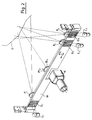
- a structure which consists essentially of three projectors with the projection optics (P1), (P2) and (P3) and three gratings (G1), (G2) and (G3), each with the same Grating period exists, which are arranged at a distance (a) behind the projection optics (P1 - P3).
- the camera sensor is labeled (K) and is located with the front observation lens (Bo) between the projectors (P1) and (P2) at a distance (a k ) behind the observation lens (Bo).
- the two projectors (P2) and (P3) arranged next to one another close a relatively small angle ( ⁇ 2) of, for example 0.5 ° on.
- the angle between the two projectors (P2, P3) arranged next to each other is small compared to the angle that the projectors (P2, P3) enclose with the axis of the camera (K).
- This arrangement defines two sets of levels of constant phase difference, namely the phase differences of the stripe patterns of the two projectors (P1) and (P2) or (P1) and (P3) and the phase differences of the two stripe patterns of the projectors (P2) and (P3) , where the two sets different effective wavelengths ( ⁇ eff ) can be assigned in the z direction.
- the effective wavelength ( ⁇ eff ) is determined by the grating constant of the grating (G1), (G2) and (G3) and the angle ( ⁇ 1) or ( ⁇ 2) between the projection axes of the respective projectors and depends on the grating constant of the grating (G1) to (G3) are the same, therefore only from the angles ( ⁇ 1) and ( ⁇ 2).
- the grids are arranged on a common support (W) made of glass or a material with a low coefficient of thermal expansion, such as Zerodur, and can be moved together relative to the CCD camera (K) in the direction of the straight line x using a spring rocker be moved without play.
- the photosensitive surface of the camera, ie the CCD sensor, is arranged at a distance (a K) behind the observation objective (Bo).
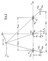
- the geometry of the measuring device is essentially determined by the structure described.
- the center (x 0k ) of the observation lens (Bo) of the camera defines the origin of the coordinate system predetermined by the projectors (P1) to (P3).
- the formulas (11), (12) and (13) describe planes of constant phase difference (N i - ⁇ i ) between two projections that are parallel to the x / y plane. They do not depend on the observation location (x k , y k ) on the camera. For the measurement, the whole numbers (N1, N2, N3) and the fractions ( ⁇ 1, ⁇ 2, ⁇ 3) must be determined.
- Different effective brightness lengths ( ⁇ eff ) of the phase differences can be assigned to the areas of the same phase difference, which are described by equations (11), (12) and (13).
- equation (11) obtained from a combination of the projectors (P1) and (P2) and the equation (12) obtained from a combination of the projectors (P1) and (P3) there are relatively short effective wavelengths, while the one obtained by equation ( 13) described case of the combination of the two projectors (P2) and (P3) a comparatively large wavelength ( ⁇ eff ) can be assigned. It is essential that the different effective wavelengths over the angle ( ⁇ 1), ( ⁇ 2) between the projectors can be set highly stable.
- the stripe patterns projected by the three projectors (P1) to (P3) in time-division multiplexing are recorded by the lens (Bo) by the camera (K) and read separately into different image memories.
- the calculation of the object coordinates (x), (y) and (z) according to the formulas given then takes place as described below with reference to FIGS. 5a and 5b in a hardware-based image processing computer.
- This computer processes the image data in real time. For this purpose it is in the form of a pipeline structure, also with partially parallel data paths is constructed and controlled by a host computer with a known von Neumann structure, ie, for example, a commercially available process computer.
- FIGS. 5a and 5b for a further description of the evaluation computer, reference is made to FIGS. 5a and 5b, in which it is shown in the block diagram.
- the functional module (A) represents the interface to the external sensors or parts of the device to be controlled. It contains an analog / digital converter (12) which digitizes the signal from the camera (K) in real-time video. The gain factor is controlled depending on the output signal of a photodiode (13), so that the video signal can be adapted to different brightness conditions or different energies of the light sources designed as flash lamps (L 1) to (L 3) (see FIGS. 2 and 4) serve to illuminate the grating (G1 - G3).
- the interface card (A) contains a trigger circuit (31) which is synchronized with the camera (K).
- the interface card (A) also contains the control electronics (32) for the motor, with which the lens (Bo) of the camera (K) can be focused on different object areas, as indicated in Fig. 2 by the arrow (Pf2).
- the sequence of the flashes and the adjustment of the lens is controlled in accordance with a defined measurement program of the conventional host computer not shown in FIG. 5. This is symbolized by the two arrows "host”, which also appear elsewhere in the circuit according to FIGS. 5a and 5b.
- the digitized video signal which leaves the A / D converter (12), is fed to the inputs of two parallel convolution modules (14a) and (14b) in the function module (B). These two building blocks (14a) and (14b) perform a convolution operation in order to determine the sine or cosine of the stripe phase at the individual pixels from the intensity profile of the signal in the vicinity of the pixels. Corresponding algorithms are described, for example, in "Optical Engineering", Vol. 23, No. 4 (July / August 1984) on pages 391 - 395.
- the outputs of the modules (14a) and (14b) are fed to a circuit (15) in which the strip phase is calculated from the sine and the cosine.
- the function arctangent is stored in a table assigned to the circuit (15).
- invalid measured values are masked on the basis of the phase values calculated in the circuit (15).
- Invalid measured values are those that were recorded with either too high or too low illumination intensity and whose level is therefore above or below a predetermined limit value.
- the mask which masks these image areas is generated in a circuit part denoted by (C) parallel to the measurement data stream, as will be described below.
- the output of the circuit (15) is fed via a calculation stage (16) (arithmetic logic unit) to three image memories (17a-c) connected in parallel.
- the stripe phases ( ⁇ 1), ( ⁇ 2) and ( ⁇ 3) calculated by the three projectors (P1), (P2) and (P3) successively projected in time-division multiplex operation are temporarily stored in the circuit (15).
- Correction values are stored in three further image memories (18a), (18b) and (18c), which were obtained in a calibration process and which describe the distortions of the stripe phase of the patterns projected by the three projectors due to the imperfection of the geometrical-optical structure of the device. These correction values are subtracted from the stripe phases ( ⁇ 1), ( ⁇ 2) and ( ⁇ 3) in the computing unit (16).
- the computing unit (19) is followed by a summation stage (S) (see FIG. 5b), which consists of a computing unit (20) and two RAM memories (21a) and (21b).
- S summation stage
- the phase differences ( ⁇ 1) and ( ⁇ 2) are accumulated for each pixel.
- This can e.g. in an integer arithmetic so that the 8-bit input values of the signals representing the phase differences ( ⁇ 1) and ( ⁇ 2) are summed up in a data area of 16 bits in the memories (22a) and (22b). In this way it is possible to average the phase differences obtained from 255 images by summation and thus to improve the accuracy of the phase measurement.
- the outputs of the image memories (21a) and (21b) are fed to two subsequent further computing units (22a) and (22b), in which the formulas for calculating the object distance according to equations (14) and ( 15) are available.
- These computing units (22a) and (22b) calculate two values for the object distance (z), which are averaged again in a subsequent computing stage (23).
- the coordinates (x) and (y) of the pixels according to equations (16) and (17) are determined from the measured values for (z) and the device constants (x k) supplied by the host computer ( y k) and (a k) calculated and fed to an output unit (25).
- the height information about the object to be measured is obtained absolutely and not only modulo 2 ⁇ of the strip phase.
- the evaluation method described above presupposes that the signals supplied by the camera (K) are generated in the linear region of the camera characteristic curve and that in particular there is no under- or over-control. Furthermore, it is necessary for the described method that within a recording series of the three stripe patterns projected by the projectors (P1), (P2) and (P3) a phase value is only processed if the phase values in all three images of the sequence for the particular one Pixels are valid. These arithmetic operations are carried out in the circuit part (C) of FIG. 5a. A bit in the look-up table LUT in the computing unit (15) queries whether a measured value is valid or invalid.
- the "and" link via the three video image sequences is generated in the computing stage (26) together with a recursively switched RAM module (27).
- the number of valid measured values at each pixel is calculated and stored in a subsequent RAM module (29).
- the number of measured values is to be understood here as the number of video images over which the phase differences in the summation module (S) of FIG. 5b are summed up. If you set an appropriately selected limit that describes a minimum number of valid measurements for each pixel, then all pixels are hidden in which the number of valid measurements is below this limit and all other pixels are included in the result calculation.
- the data mask described in this way, placed over the pixels is symbolized by the square designated (30) in FIG. 5a. It can be used to darken the video monitor (42) used for output at the corresponding pixels.
- the evaluation computer implemented in hardware and described with reference to FIGS. 5a and 5b represents a solution with which the signals of the camera can be processed in order to carry out the method according to the invention.
- This solution is tailored so that the stripe pattern through the three Projectors (P1), (P2) and (P3) are projected one after the other in time division multiplex operation and the images are then taken and processed one after the other by the camera (K).
- P1, P2 and P3 are projected one after the other in time division multiplex operation and the images are then taken and processed one after the other by the camera (K).
- K the camera
- the input channel ie the A / D converter (12), the convection modules (14a) and (14b), the computing units (15) and (16), which operate in time-division multiplex operation, must be executed in parallel in a corresponding number of three become.
- the arithmetic operations described can also be executed on a suitably programmed, suitably powerful, sequentially operating computer of conventional structure, but only there with considerably longer runtimes, so that real-time processing of the video signals cannot be achieved in this case.
- the carrier (W) with the Grids (G1) to (G3) can be moved in the direction of the arrow (Pf1) without influencing the z values obtained in the signal evaluation.
- the illumination intensity can be controlled from the value zero to saturation, so that useful measured values can be obtained from all object points, the reflectivity of which can be quite different.
- the masking electronics in part (C) of the circuit of FIG. 5a ensure that all measurements in the non-linear region of the camera (K) are rejected.
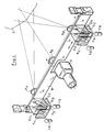
- FIG. 3 and 4 a second, alternative embodiment of the invention is shown.
- the sketch of the second embodiment in Fig. 3 shows the basic structure of the measuring device, which consists essentially of two projection optics (P11) and (P12) and four gratings (G11 / G13) and (G12 / G14) .
- the camera sensor is again designated (K) and is located with the observation lens (Bo) between the projectors (P11) and (P12).
- each of the two projectors (P11) and (P12) contains two gratings and the grating constants or grating periods of two gratings (G11) and (G12) and (G13) and (G14) are the same in pairs.
- the grating constants or periods of the grating (G11) and (G13) or (G12) and G14) differ slightly within a projector.
- the grid (G11) has a grid constant of 25 line pairs / mm and the grid (G13) has a grid constant of 25.5 line pairs / mm.
- This arrangement allows two slightly different sets of levels of constant phase difference to be defined, namely the phase differences between the grids (G11) and (G12) and (G12) projected in pairs and the phase differences between the grids (G13) and (G14) projected in pairs.
- this can be an effective wavelength assign that is much larger than the effective wavelengths ⁇ 1 or ⁇ 2 assigned to the surfaces of the same phase difference.
- This equation (22) describes a function with a much longer effective wavelength compared to equation (20) or (21).
- the object distance z can be determined from this in a manner very similar to that described with reference to FIG. 5, in that the fraction of the phases after the decimal point ⁇ 11, ⁇ 12, ⁇ 21, ⁇ 22 the stripe pattern projected through the four grids (G11) to (G14) measured and evaluated according to equation (22).
- the four stripe patterns are projected separately, so that only one defined stripe pattern is created and can be evaluated on the surface of the camera sensor (K), so that the intensities of different stripe patterns do not overlap and interfere with the evaluation.
- the two gratings (G11) and (G13) behind the projection optics (P11) are placed on the surfaces of a first beam splitter cube (S11) and the two gratings (G12) and (G14) behind the projection optics (P12 ) placed on the surfaces of a second beam splitter cube (S12).
- the grating pairs (G11) and (G13) are illuminated by two different light sources (L11) and (L13) through color filters (F11) and (F13) through, so that stripe patterns in different colors arise, which can be processed separately by a color camera (K).
- the separation of the pair of gratings (G12, G14) is done in the same way with color filters (F12) and (F14), which are illuminated by two lamps (L12) and (L14).
Landscapes
- Engineering & Computer Science (AREA)
- Physics & Mathematics (AREA)
- Computer Vision & Pattern Recognition (AREA)
- General Physics & Mathematics (AREA)
- Optics & Photonics (AREA)
- Theoretical Computer Science (AREA)
- Length Measuring Devices By Optical Means (AREA)
- Measurement Of Optical Distance (AREA)
Claims (10)
- Procédé pour mesurer les surfaces d'objets, sur lequel, pour augmenter la plage de mesure dans la direction de l'axe (z) de la caméra, on projette plusieurs mires de barres (G₁, G₂, G₃) à une périodicité égale ou légèrement différente sur la surface (O) de l'objet, ces mires de barres, déformées par la surface (O) de l'objet étant prises par une caméra (K) et les mires de barres ainsi prises sont exploitées, procédé caractérisé en ce que les mires de barres, prises sont appliquées séparément les unes des autres à un calculateur de traitement d'image, et celui-ci, partant des mires de barres, prises donne au moins deux fréquences de battement de longueurs d'ondes effectives très différentes et en ce qu'on détermine la distance (z) de l'objet à l'aide d'au moins deux fréquences de battement.
- Procédé selon la revendication 1, caractérisé en ce que les fréquences de battement sont créées dans le calculateur en formant les différences (Δ₁, Δ₂, Δ₃) des phases de barres (δ₁, δ₂, δ₃) des mires de barres prises.
- Procédé selon la revendication 1, caractérisé en ce que l'on projette trois réseaux (G₁, G₂, G₃) de même périodicité suivant des angles (α₁, α₂) différents sur l'objet.
- Procédé selon la revendication 3, caractérisé en ce qu'on place les trois réseaux (G₁, G₂, G₃) dans un plan commun.
- Procédé selon la revendication 1, caractérisé en ce qu'on projette les mires de barres à l'aide de deux projecteurs (P₁₁, P₁₂), chaque projecteur (P₁₁, P₁₂) ayant deux réseaux (G₁₁, G₁₃ ; G₁₂, G₁₄) de périodicité légèrement différente et deux réseaux (G₁₁, G₁₃) d'un projecteur (P₁₁) ayant la même périodicité que les deux réseaux (G₁₂, G₁₄) de l'autre projecteur (P₁₂).
- Dispositif pour mesurer des surfaces d'objets à l'aide de projecteurs qui projettent des mires de barres de même périodicité sur l'objet (O) et d'une caméra (K) qui prend leur image à la surface de l'objet et d'un calculateur de traitement d'image qui détermine l'information de hauteur (z) des différents points de la surface de l'objet à partir des signaux vidéo de la caméra (K), dispositif caractérisé par au moins deux projecteurs (P₂, P₃) et qui sont associés suivant un angle relatif petit par rapport à l'angle qu'elles font par rapport à l'axe de la caméra (K), les images de caméra enregistrées pour la projection par des projecteurs différents (P₂, P₃) étant appliquées séparément au calculateur de traitement d'image et en ce que ce calculateur crée au moins deux fréquences de battement différentes avec des longueurs d'ondes effectives différentes à partir des images de caméra enregistrées et est conçu pour calculer la distance (z) de l'objet à l'aide de ces fréquences de battement.
- Dispositif selon la revendication 6, caractérisé par au moins trois projeteurs (P₁, P₂, P₃) qui projettent des mires de barres de même périodicité et en ce que les réseaux (G₁, G₂, G₃) servant à la projection sont montés sur un même support (W) ou substrat commun.
- Dispositif selon la revendication 7, caractérisé en ce que le support ou le substrat est mobile par rapport à l'axe de la caméra (K) dans le plan des réseaux (G₁, G₂, G₃).
- Dispositif pour mesurer les surfaces d'objets à l'aide d'au moins un projecteur qui projette des mires de barres de périodicité différente sur l'objet (O) et d'une caméra (K) qui prend une image de la surface de l'objet, ainsi que d'un calculateur de traitement d'image qui, partant des signaux vidéo de la caméra (K), donne l'information de hauteur (z) des différents points de la surface de l'objet, dispositif caractérisé par deux projecteurs (P₁, P₂) et à chacun des deux projecteurs sont associés deux réseaux (G₁₁, G₁₃/G₁₂, G₁₄) à périodicité de réseau légèrement différence, et on les projette séparément, la périodicité dès réseaux (G₁₁ ; G₁₃) d'un projecteur (P₁) étant égale par paire à la périodicité des deux réseaux (G₁₂, G₁₄) de l'autre projecteur (P₂), les mires de barres déformées par la surface de l'objet et prises en vue par la caméra (K) étant appliquées séparément au calculateur de traitement d'image qui est réalisé pour créer au moins deux fréquences de battement à longueurs d'ondes effectives très différentes à partir des images prises par la caméra et pour calculer la distance de l'objet (Z) à l'aide de ces fréquences de battement.
- Dispositif selon la revendication 9, caractérisé en ce que les projecteurs comportent des diviseurs de couleurs (F₁₁/F₁₂, F₁₃/F₁₄) pour séparer les mires de barres et la caméra (K) est une caméra en couleurs.
Applications Claiming Priority (2)
| Application Number | Priority Date | Filing Date | Title |
|---|---|---|---|
| DE4007500 | 1990-03-09 | ||
| DE4007500A DE4007500A1 (de) | 1990-03-09 | 1990-03-09 | Verfahren und vorrichtung zur beruehrungslosen vermessung von objektoberflaechen |
Publications (3)
| Publication Number | Publication Date |
|---|---|
| EP0445618A2 EP0445618A2 (fr) | 1991-09-11 |
| EP0445618A3 EP0445618A3 (en) | 1992-03-11 |
| EP0445618B1 true EP0445618B1 (fr) | 1995-01-04 |
Family
ID=6401802
Family Applications (1)
| Application Number | Title | Priority Date | Filing Date |
|---|---|---|---|
| EP91102736A Expired - Lifetime EP0445618B1 (fr) | 1990-03-09 | 1991-02-25 | Dispositif et procédé pour mesurer sans contact la superficie d'objets |
Country Status (4)
| Country | Link |
|---|---|
| US (1) | US5135309A (fr) |
| EP (1) | EP0445618B1 (fr) |
| JP (1) | JPH04220509A (fr) |
| DE (2) | DE4007500A1 (fr) |
Families Citing this family (52)
| Publication number | Priority date | Publication date | Assignee | Title |
|---|---|---|---|---|
| US5343294A (en) * | 1990-03-09 | 1994-08-30 | Carl-Zeiss-Stiftung | Method for analyzing periodic brightness patterns |
| NL9200071A (nl) * | 1992-01-15 | 1993-08-02 | Stichting Science Park Maastri | Inrichting voor het bepalen van de topografie van een gekromd oppervlak. |
| DE4217768A1 (de) * | 1992-05-29 | 1993-12-02 | Zeiss Carl Fa | Verfahren und Vorrichtung zur Vermessung von Objekttopographien mittels projizierter Streifenmuster |
| DE4416108C2 (de) * | 1994-05-06 | 2000-05-11 | Fraunhofer Ges Forschung | Vorrichtung zum berührungsfreien Vermessen einer Objektoberfläche |
| JP2919267B2 (ja) * | 1994-05-26 | 1999-07-12 | 松下電工株式会社 | 形状検出方法およびその装置 |
| US6028672A (en) * | 1996-09-30 | 2000-02-22 | Zheng J. Geng | High speed three dimensional imaging method |
| DE19637682B4 (de) * | 1996-09-05 | 2004-04-29 | Fraunhofer-Gesellschaft zur Förderung der angewandten Forschung e.V. | Verfahren zur Bestimmung der räumlichen Koordinaten von Gegenständen und/oder deren zeitlicher Änderung und Vorrichtung zur Anwendung dieses Verfahrens |
| US5838428A (en) * | 1997-02-28 | 1998-11-17 | United States Of America As Represented By The Secretary Of The Navy | System and method for high resolution range imaging with split light source and pattern mask |
| DE19749435B4 (de) * | 1997-11-09 | 2005-06-02 | Mähner, Bernward | Verfahren und Vorrichtung zur dreidimensionalen, flächenhaften, optischen Vermessung von Objekten |
| DE19846145A1 (de) * | 1998-10-01 | 2000-04-20 | Klaus Koerner | Verfahren und Anordung zur 3D-Aufnahme |
| GB9824986D0 (en) * | 1998-11-13 | 1999-01-06 | Isis Innovation | Non-contact topographical analysis apparatus and method thereof |
| US6763133B1 (en) * | 1999-05-29 | 2004-07-13 | Sun Moon University | Moire image capturing apparatus and method therefor |
| US6100990A (en) * | 1999-06-14 | 2000-08-08 | Ford Motor Company | Method and apparatus for determining reflective optical quality using gray-scale patterns |
| US6208412B1 (en) | 1999-06-14 | 2001-03-27 | Visteon Global Technologies, Inc. | Method and apparatus for determining optical quality |
| US7358986B1 (en) * | 2000-09-13 | 2008-04-15 | Nextengine, Inc. | Digital imaging system having distribution controlled over a distributed network |
| CA2422242A1 (fr) * | 2000-09-13 | 2002-03-21 | Nextengine, Inc. | Surveillance et commande d'un systeme d'imagerie permettant d'assurer la fidelite d'un enregistrement d'image capturee |
| US6639684B1 (en) * | 2000-09-13 | 2003-10-28 | Nextengine, Inc. | Digitizer using intensity gradient to image features of three-dimensional objects |
| US6856407B2 (en) | 2000-09-13 | 2005-02-15 | Nextengine, Inc. | Method for depth detection in 3D imaging providing a depth measurement for each unitary group of pixels |
| JP2002213931A (ja) * | 2001-01-17 | 2002-07-31 | Fuji Xerox Co Ltd | 3次元形状計測装置および3次元形状計測方法 |
| US7233351B1 (en) | 2001-02-23 | 2007-06-19 | Nextengine, Inc. | Method for high resolution incremental imaging |
| JP3519698B2 (ja) * | 2001-04-20 | 2004-04-19 | 照明 與語 | 3次元形状測定方法 |
| DE10125971A1 (de) | 2001-05-29 | 2002-12-05 | Leica Mikroskopie Systeme Ag H | Verfahren zur Entfernungsmessung ausgedehnter Objekte in Verbindung mit einer optischen Betrachtungseinrichtung und Mikroskop zur Durchführung desselben |
| DE10130902A1 (de) * | 2001-06-27 | 2003-01-16 | Zeiss Carl | Interferometersystem, Verfahren zum Aufnehmen eines Interferogramms und Verfahren zum Bereitstellen und Herstellen eines Objekts mit einer Soll-Oberfläche |
| US6634552B2 (en) * | 2001-09-26 | 2003-10-21 | Nec Laboratories America, Inc. | Three dimensional vision device and method, and structured light bar-code patterns for use in the same |
| EP1625350A1 (fr) * | 2003-03-18 | 2006-02-15 | Alexander Thomas Hermary | Detecteur a balayage de profil a double observation et lumiere codee |
| US7711179B2 (en) | 2004-04-21 | 2010-05-04 | Nextengine, Inc. | Hand held portable three dimensional scanner |
| US20060045174A1 (en) * | 2004-08-31 | 2006-03-02 | Ittiam Systems (P) Ltd. | Method and apparatus for synchronizing a transmitter clock of an analog modem to a remote clock |
| DE102004044695A1 (de) * | 2004-09-15 | 2006-03-30 | Sick Ag | Verfahren und Vorrichtung zur Abstandsmessung |
| JP4628762B2 (ja) * | 2004-11-30 | 2011-02-09 | 株式会社ニデック | 眼科測定装置 |
| US7830528B2 (en) | 2005-12-14 | 2010-11-09 | Koh Young Technology, Inc. | 3D image measuring apparatus and method thereof |
| KR100612932B1 (ko) * | 2005-12-14 | 2006-08-14 | 주식회사 고영테크놀러지 | 3차원 형상 측정장치 및 방법 |
| US7995834B1 (en) | 2006-01-20 | 2011-08-09 | Nextengine, Inc. | Multiple laser scanner |
| US20080117438A1 (en) * | 2006-11-16 | 2008-05-22 | Solvision Inc. | System and method for object inspection using relief determination |
| US20080156619A1 (en) | 2006-12-01 | 2008-07-03 | Mehul Patel | Range finder |
| FR2910123B1 (fr) * | 2006-12-19 | 2009-01-23 | Phosylab Sarl | Procede optico-informatique de mesure 3d de la surface exterieure d'un objet en relief par projection de franges et utilisation d'une methode a decalage de phase, systeme correspondant |
| WO2009024756A1 (fr) | 2007-08-17 | 2009-02-26 | Renishaw Plc | Appareil et procédé de mesure sans contact |
| CN100455987C (zh) * | 2007-08-23 | 2009-01-28 | 北京交通大学 | 利用合成波干涉全场纳米表面三维在线测量方法和系统 |
| US7768656B2 (en) * | 2007-08-28 | 2010-08-03 | Artec Group, Inc. | System and method for three-dimensional measurement of the shape of material objects |
| WO2009094510A1 (fr) * | 2008-01-25 | 2009-07-30 | Cyberoptics Corporation | Capteur à sources multiples pour une imagerie tridimensionnelle utilisant une lumière structurée à phases |
| US8422030B2 (en) * | 2008-03-05 | 2013-04-16 | General Electric Company | Fringe projection system with intensity modulating by columns of a plurality of grating elements |
| US7969583B2 (en) * | 2008-03-05 | 2011-06-28 | General Electric Company | System and method to determine an object distance from a reference point to a point on the object surface |
| DE102008015499C5 (de) * | 2008-03-25 | 2013-01-10 | Steinbichler Optotechnik Gmbh | Verfahren und Vorrichtung zur Bestimmung der 3D-Koordinaten eines Objekts |
| GB0915904D0 (en) | 2009-09-11 | 2009-10-14 | Renishaw Plc | Non-contact object inspection |
| EP2314200B1 (fr) * | 2009-10-21 | 2016-01-13 | SIS AG, Surgical Instrument Systems | Dispositif et procédé destinés à la mesure d'une cornée |
| US8414124B2 (en) | 2009-10-21 | 2013-04-09 | Sis Ag, Surgical Instrument Systems | Device and method for measuring a cornea |
| JP2014182028A (ja) * | 2013-03-19 | 2014-09-29 | Omron Corp | 限定領域反射型光電センサ |
| EP2799810A1 (fr) * | 2013-04-30 | 2014-11-05 | Aimess Services GmbH | Dispositif et procédé de mesure tridimensionnelle simultanée de surfaces avec plusieurs longueurs d'onde |
| US10417472B2 (en) * | 2014-01-10 | 2019-09-17 | Koh Young Technology Inc. | Device and method for measuring three-dimensional shape |
| US10643343B2 (en) | 2014-02-05 | 2020-05-05 | Creaform Inc. | Structured light matching of a set of curves from three cameras |
| EP3064893B1 (fr) * | 2015-03-05 | 2019-04-24 | Leuze electronic GmbH + Co KG | Capteur optique |
| EP3688407B1 (fr) * | 2017-09-27 | 2024-07-31 | AMS Sensors Singapore Pte. Ltd. | Systèmes de projection de lumière |
| CN110230994B (zh) * | 2019-04-30 | 2020-08-14 | 浙江大学 | 像点溯源的物体光栅图像相移法相位测量误差校正方法 |
Family Cites Families (9)
| Publication number | Priority date | Publication date | Assignee | Title |
|---|---|---|---|---|
| US3627427A (en) * | 1970-02-11 | 1971-12-14 | Lockheed Aircraft Corp | Method and apparatus for contour measurement |
| FR2279066A1 (fr) * | 1974-07-15 | 1976-02-13 | Morin Secretan Rech Perfection | Procede de visualisation directe de la forme et des deformations d'un objet tridimensionnel |
| FR2292213A1 (fr) * | 1974-11-21 | 1976-06-18 | Cem Comp Electro Mec | Procede et dispositif permettant de determiner le signe des lignes de niveau d'un objet |
| US4499492A (en) * | 1982-08-18 | 1985-02-12 | Novon, Inc. | Method and apparatus for three frame range imaging |
| US4488172A (en) * | 1982-08-18 | 1984-12-11 | Novon, Inc. | Method and apparatus for range imaging |
| US4564295A (en) * | 1983-03-07 | 1986-01-14 | New York Institute Of Technology | Apparatus and method for projection moire topography |
| US4641972A (en) * | 1984-09-14 | 1987-02-10 | New York Institute Of Technology | Method and apparatus for surface profilometry |
| EP0262089A3 (fr) * | 1986-09-23 | 1989-08-09 | KERN & CO. AG Werke für Präzisionsmechanik Optik und Elektronik | Dispositif pour mesurer la surface d'un objet |
| US4871256A (en) * | 1987-04-29 | 1989-10-03 | Lbp Partnership | Means for projecting patterns of light |
-
1990
- 1990-03-09 DE DE4007500A patent/DE4007500A1/de not_active Withdrawn
-
1991
- 1991-02-25 DE DE59104107T patent/DE59104107D1/de not_active Expired - Fee Related
- 1991-02-25 EP EP91102736A patent/EP0445618B1/fr not_active Expired - Lifetime
- 1991-03-08 JP JP3043365A patent/JPH04220509A/ja active Pending
- 1991-03-08 US US07/666,247 patent/US5135309A/en not_active Expired - Lifetime
Also Published As
| Publication number | Publication date |
|---|---|
| DE4007500A1 (de) | 1991-09-12 |
| EP0445618A2 (fr) | 1991-09-11 |
| EP0445618A3 (en) | 1992-03-11 |
| US5135309A (en) | 1992-08-04 |
| DE59104107D1 (de) | 1995-02-16 |
| JPH04220509A (ja) | 1992-08-11 |
Similar Documents
| Publication | Publication Date | Title |
|---|---|---|
| EP0445618B1 (fr) | Dispositif et procédé pour mesurer sans contact la superficie d'objets | |
| EP0451474B1 (fr) | Procédé et dispositif pour mesurer sans contact le contour superficiel d'un objet | |
| EP0076866B1 (fr) | Procédé interpolant de la coupe optique | |
| DE69207176T2 (de) | Optischer Sensor | |
| DE102008002730B4 (de) | Verfahren und Vorrichtung zur 3D-Rekonstruktion | |
| EP3298345B1 (fr) | Caméra et procédé pour réaliser une mesure en 3d et une mesure de couleur d'un objet dentaire | |
| DE9017720U1 (de) | Vorrichtung zur direkten Phasenmessung von Strahlung, insbesondere Lichtstrahlung | |
| WO2009063088A2 (fr) | Procédé de mesure optique d'objets en utilisant une méthode de triangulation | |
| CH626169A5 (fr) | ||
| EP0449859B1 (fr) | Procede et dispositif d'observation de moirures sur des surfaces a examiner par moirage a dephasage | |
| DE102009009372A1 (de) | Monitoring von kippbaren Spiegeln | |
| EP2799810A1 (fr) | Dispositif et procédé de mesure tridimensionnelle simultanée de surfaces avec plusieurs longueurs d'onde | |
| DE102014113389A1 (de) | Verfahren und Vorrichtung zum Identifizieren von Strukturelementen eines projizierten Strukturmusters in Kamerabildern | |
| EP1485670A2 (fr) | Procede et dispositif pour determiner les coordonnees absolues d'un objet | |
| DE69104010T2 (de) | Verfahren und Vorrichtung zur Messung der Qualität einer Glasscheibe. | |
| WO1998010244A1 (fr) | Procede et dispositif de determination des coordonnees spatiales d'objets | |
| DE2539183C2 (de) | Optisches Meßinstrument | |
| DE19633686C2 (de) | Vorrichtung und Verfahren zur Vermessung von Entfernungen und/oder räumlichen Koordinaten von Gegenständen und/oder deren zeitlicher Änderung | |
| WO2012076182A1 (fr) | Procédé et système pour la détermination de la position et/ou de la situation d'un objet dans un volume de mesure spatial | |
| DE2620330A1 (de) | Verfahren und vorrichtung zur bestimmung einer oberflaechengestalt | |
| DE2653545B1 (de) | Fotoelektrische Auflicht-Wegmesseinrichtung | |
| DE69116887T2 (de) | Ortungsbestimmung | |
| DE102023205077B4 (de) | Verfahren und Vorrichtung zur Bestimmung einer objektabhängigen Fokusablage, Verfahren zur Vermessung eines Objekts und Koordinatenmessgerät | |
| DE4129796A1 (de) | Verfahren und vorrichtung zur beruehrungslosen vermessung von objektoberflaechen | |
| DE102009006089B4 (de) | Verfahren zur Zuordnung von Bildpunkten |
Legal Events
| Date | Code | Title | Description |
|---|---|---|---|
| PUAI | Public reference made under article 153(3) epc to a published international application that has entered the european phase |
Free format text: ORIGINAL CODE: 0009012 |
|
| AK | Designated contracting states |
Kind code of ref document: A2 Designated state(s): CH DE FR GB IT LI |
|
| PUAL | Search report despatched |
Free format text: ORIGINAL CODE: 0009013 |
|
| AK | Designated contracting states |
Kind code of ref document: A3 Designated state(s): CH DE FR GB IT LI |
|
| 17P | Request for examination filed |
Effective date: 19920908 |
|
| 17Q | First examination report despatched |
Effective date: 19930928 |
|
| GRAA | (expected) grant |
Free format text: ORIGINAL CODE: 0009210 |
|
| AK | Designated contracting states |
Kind code of ref document: B1 Designated state(s): CH DE FR GB IT LI |
|
| PG25 | Lapsed in a contracting state [announced via postgrant information from national office to epo] |
Ref country code: IT Free format text: LAPSE BECAUSE OF FAILURE TO SUBMIT A TRANSLATION OF THE DESCRIPTION OR TO PAY THE FEE WITHIN THE PRESCRIBED TIME-LIMIT;WARNING: LAPSES OF ITALIAN PATENTS WITH EFFECTIVE DATE BEFORE 2007 MAY HAVE OCCURRED AT ANY TIME BEFORE 2007. THE CORRECT EFFECTIVE DATE MAY BE DIFFERENT FROM THE ONE RECORDED. Effective date: 19950104 |
|
| ET | Fr: translation filed | ||
| REF | Corresponds to: |
Ref document number: 59104107 Country of ref document: DE Date of ref document: 19950216 |
|
| GBT | Gb: translation of ep patent filed (gb section 77(6)(a)/1977) |
Effective date: 19950315 |
|
| PLBE | No opposition filed within time limit |
Free format text: ORIGINAL CODE: 0009261 |
|
| STAA | Information on the status of an ep patent application or granted ep patent |
Free format text: STATUS: NO OPPOSITION FILED WITHIN TIME LIMIT |
|
| 26N | No opposition filed | ||
| REG | Reference to a national code |
Ref country code: GB Ref legal event code: IF02 |
|
| PGFP | Annual fee paid to national office [announced via postgrant information from national office to epo] |
Ref country code: CH Payment date: 20070214 Year of fee payment: 17 |
|
| PGFP | Annual fee paid to national office [announced via postgrant information from national office to epo] |
Ref country code: DE Payment date: 20070216 Year of fee payment: 17 Ref country code: GB Payment date: 20070216 Year of fee payment: 17 |
|
| PGFP | Annual fee paid to national office [announced via postgrant information from national office to epo] |
Ref country code: FR Payment date: 20070212 Year of fee payment: 17 |
|
| REG | Reference to a national code |
Ref country code: CH Ref legal event code: PL |
|
| GBPC | Gb: european patent ceased through non-payment of renewal fee |
Effective date: 20080225 |
|
| PG25 | Lapsed in a contracting state [announced via postgrant information from national office to epo] |
Ref country code: LI Free format text: LAPSE BECAUSE OF NON-PAYMENT OF DUE FEES Effective date: 20080229 Ref country code: CH Free format text: LAPSE BECAUSE OF NON-PAYMENT OF DUE FEES Effective date: 20080229 |
|
| REG | Reference to a national code |
Ref country code: FR Ref legal event code: ST Effective date: 20081031 |
|
| PG25 | Lapsed in a contracting state [announced via postgrant information from national office to epo] |
Ref country code: DE Free format text: LAPSE BECAUSE OF NON-PAYMENT OF DUE FEES Effective date: 20080902 |
|
| PG25 | Lapsed in a contracting state [announced via postgrant information from national office to epo] |
Ref country code: FR Free format text: LAPSE BECAUSE OF NON-PAYMENT OF DUE FEES Effective date: 20080229 |
|
| PG25 | Lapsed in a contracting state [announced via postgrant information from national office to epo] |
Ref country code: GB Free format text: LAPSE BECAUSE OF NON-PAYMENT OF DUE FEES Effective date: 20080225 |