EP0445564A1 - Method for regulating flow directions of a headbox in a paper machine - Google Patents
Method for regulating flow directions of a headbox in a paper machine Download PDFInfo
- Publication number
- EP0445564A1 EP0445564A1 EP19910102273 EP91102273A EP0445564A1 EP 0445564 A1 EP0445564 A1 EP 0445564A1 EP 19910102273 EP19910102273 EP 19910102273 EP 91102273 A EP91102273 A EP 91102273A EP 0445564 A1 EP0445564 A1 EP 0445564A1
- Authority
- EP
- European Patent Office
- Prior art keywords
- headbox
- flow
- raw material
- flow rate
- widthwise direction
- Prior art date
- Legal status (The legal status is an assumption and is not a legal conclusion. Google has not performed a legal analysis and makes no representation as to the accuracy of the status listed.)
- Withdrawn
Links
Images


Classifications
-
- D—TEXTILES; PAPER
- D21—PAPER-MAKING; PRODUCTION OF CELLULOSE
- D21F—PAPER-MAKING MACHINES; METHODS OF PRODUCING PAPER THEREON
- D21F1/00—Wet end of machines for making continuous webs of paper
- D21F1/02—Head boxes of Fourdrinier machines
- D21F1/022—Means for injecting material into flow within the headbox
-
- D—TEXTILES; PAPER
- D21—PAPER-MAKING; PRODUCTION OF CELLULOSE
- D21F—PAPER-MAKING MACHINES; METHODS OF PRODUCING PAPER THEREON
- D21F1/00—Wet end of machines for making continuous webs of paper
- D21F1/02—Head boxes of Fourdrinier machines
-
- D—TEXTILES; PAPER
- D21—PAPER-MAKING; PRODUCTION OF CELLULOSE
- D21F—PAPER-MAKING MACHINES; METHODS OF PRODUCING PAPER THEREON
- D21F1/00—Wet end of machines for making continuous webs of paper
- D21F1/02—Head boxes of Fourdrinier machines
- D21F1/026—Details of the turbulence section
-
- D—TEXTILES; PAPER
- D21—PAPER-MAKING; PRODUCTION OF CELLULOSE
- D21F—PAPER-MAKING MACHINES; METHODS OF PRODUCING PAPER THEREON
- D21F1/00—Wet end of machines for making continuous webs of paper
- D21F1/02—Head boxes of Fourdrinier machines
- D21F1/028—Details of the nozzle section
-
- D—TEXTILES; PAPER
- D21—PAPER-MAKING; PRODUCTION OF CELLULOSE
- D21F—PAPER-MAKING MACHINES; METHODS OF PRODUCING PAPER THEREON
- D21F1/00—Wet end of machines for making continuous webs of paper
- D21F1/06—Regulating pulp flow
Definitions
- the present invention relates to a method for regulating flow directions of raw material jet flows, which is applicable to a headbox in a paper machine.
- FIG. 9 A headbox in a paper machine in the prior art is illustrated in a perspective view in Fig. 9.
- reference numeral 1 denotes a headbox main body
- numeral 2 denotes header pipes
- numeral 3 denotes a slit-shaped jet port
- numeral 4 denotes a wire
- numeral 5 denotes a header pipe block, which is a part integrating a large number of header pipes together.
- the headbox operates to make raw paper material coming out of the header pipes 2 jet from the slit-shaped jet port 3 uniformly in the widthwise direction of the wire 4.
- correction for the flow rate of the raw material jetted from the jet port 3 is effected taking into consideration the fact that there exists influence of friction of the flow passageways inside of the headbox 1 and even after it has been jetted onto the wire 4, liquid at the side edge portions of the wire would flow outwards.
- this method for correcting the flow rate in the prior art, either one of the following two methods was used:
- a more specific object of the present invention is to provide a method for regulating flow directions, in which not only uneven flow rate is corrected, but also correction of jet flow directions which was difficult in the prior art, can be also realized.
- a method for regulating flow directions of raw material jet flows of a headbox in a paper machine provided with liquid branching header pipes directed from the upstream of a flow passageway to the downstream as arrayed along the widthwise direction of the paper machine consisting of the steps of providing a header pipe block having such header pipes that a flow rate through a header pipe or pipes at at least one end in the widthwise direction of the paper machine is set or made variable so as to be set larger than a flow rate through a header pipe or pipes at the central portion, and/or a piping or pipings disposed on at least one of the end surfaces in the widthwise direction of a flow passageway within the headbox at the downstream of the header pipes and capable of feeding liquid into the headbox and a piping or pipings disposed at at least one end in the widthwise direction of a flow passageway within the headbox at the downstream of the header pipes and capable of extracting the raw material within the headbox to the outside of the headbox, increasing the flow rates at
- the reduction of the flow rate at the end portions caused by friction of the flow passageway within the headbox is supplemented, furthermore by partly extracting the raw material from the end portions, the surplus amount of the increased flow rate at the end portions are reduced and also the inwardly directed flow caused by the surplus of the flow rate at the end portions can be corrected.
- a first preferred embodiment of the present invention will be explained with reference to Fig. 1. It is to be noted that in Fig. 1, since a headbox main body 1, header pipes 2, a jet port 3 and a wire 4 are identical to those used in the headbox in the prior art shown in Fig. 9, detailed description thereof will be omitted, and in the following only characteristic points of the present invention will be described.
- Fig. 2 is a cross-section front view of a header pipe block 5, in which provision is made such that a flow rate through the end portion may be larger than a flow rate through the central portion, by selecting an inner diameter d 2 of a header pipe 2b in the end portion larger than an inner diameter d 1 of a header pipe 2a in the inside portion. While the header pipes 2b having the inner diameter d 2 are provided only in one column at each end in Fig.
- header pipes 2b may be provided in two columns at the respective ends, a number of header pipes having a larger inner diameter may be different between the respective ends, the inner diameter of the header pipes may be different between the upper ones and the lower ones, or the size of the inner diameter may be varied into three or more kinds.
- Fig. 3 shows a B - B cross-section in Fig. 1, in which provision is made such that a part of the raw material at the end portions within the headbox can be extracted to the outside of the headbox through pipings 7 disposed symmetrically at the opposite ends on the upstream side of a slit-shaped jet port 3. Since the inner pressure of the headbox is higher than the atmospheric pressure, provided that the inner diameter of the pipings 7 is chosen sufficiently large, the raw material can be extracted from the headbox merely by opening the pipings 7 to the atmosphere.
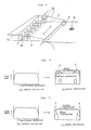
- Fig. 4 shows a flow rate distribution along the widthwise direction and flow directions improved according to the present invention. If the flow rates at the end portions increase as compared to that in the central portion by disposing the header pipe block shown in Fig. 2, then as shown in Fig. 4(b) the flow rates at the end portions would become large as compared to that before correction shown in Fig. 4(a). By the way, since liquid would flow in such direction that its flow rate may become uniform according to a general property of a liquid flow, the flow directions would be directed inwards as shown in Fig. 4(b).
- Fig. 5 shows one modified embodiment, in which a sleeve 9 is fitted to the inside of the header pipe 2 in such manner that the sleeve may not slip out due to the pressure of the raw material.
- the flow rates through the end portions can be made larger than the flow rate through the central portion.
- flow rate balance between the end portions and the central portion as shown in Fig. 4(c) can be changed in a relatively simple manner by replacing the sleeves 9.
- a tube 10 made of elastic material such as rubber or the like is disposed inside of the header pipe 2, and by applying a pressure to the inside of the tube 10 through a duct 11 the tube 10 is deformed as shown in Fig. 6(b).
- the flow rate through the header pipe in the end portion can be made larger than the flow rate through the header pipe in the central portion.
- the flow rate balance between the end portions and the central portion can be changed.
- a correction effect for the flow directions can be attained as shown in Fig. 4(c).
- Fig. 8 shows another preferred embodiment which is different from that shown in Fig. 7, in which owing to the fact that pipings 13 are inserted into the headbox as bent along the pond-sides 6, the fear of disturbing flow directions within the headbox is less than the embodiment shown in Fig. 7.
- the essence of the present invention resides in the header pipe block having header pipes which are preset in such manner that the flow rates through the header pipes in the end portions of the headbox may be larger than the flow rate through the header pipe in the central portion, and/or the pipings disposed at the end portions of the flow passageway and capable of feeding the liquid in the headbox, and the pipings capable of extracting the raw material in the headbox to the outside from the end portions of the flow passageway.
- the jet flow directions of the headbox can be aligned in the same direction. According to results of experiments, flow directions directed outwards by 0.2° before correction became to direct inwards by 0.1° by supplementing the raw material to increase the flow rates at the opposite end portions, and furthermore, by extracting the raw material to decrease the flow rates at the opposite end portions, the jet directions could be aligned in the same direction.
- orientation angles of fibers of ⁇ 4° prior to correction were improved up to ⁇ 2° or less. It is to be noted that the orientation angles of fibers as referred to above are experimental values measured by a sonic sheet tester.
Abstract

Description
- The present invention relates to a method for regulating flow directions of raw material jet flows, which is applicable to a headbox in a paper machine.
- A headbox in a paper machine in the prior art is illustrated in a perspective view in Fig. 9. In this figure, reference numeral 1 denotes a headbox main body,
numeral 2 denotes header pipes,numeral 3 denotes a slit-shaped jet port,numeral 4 denotes a wire, andnumeral 5 denotes a header pipe block, which is a part integrating a large number of header pipes together. The headbox operates to make raw paper material coming out of theheader pipes 2 jet from the slit-shaped jet port 3 uniformly in the widthwise direction of thewire 4. - In addition, at the end portions of the jet liquid, correction for the flow rate of the raw material jetted from the
jet port 3 is effected taking into consideration the fact that there exists influence of friction of the flow passageways inside of the headbox 1 and even after it has been jetted onto thewire 4, liquid at the side edge portions of the wire would flow outwards. As this method for correcting the flow rate, in the prior art, either one of the following two methods was used: - (1) Supplementary raw material is made to flow by providing
bypass flow passageways 14 at the end portions of theheader pipe block 5 in Fig. 9. - (2) A part of the raw material is extracted to the outside of the headbox by providing pipings in the proximities of the end portions of the
jet port 3. - However, in the method for correcting the flow rates in the prior art, though it was possible to make the raw material to be jetted from the slit-
shaped jet port 3 so that the flow rate of the raw material may be uniform along the widthwise direction of the wire, it was difficult to align the directions of the jet flow in the same direction over the entire width. - More particularly, with only the method of making supplementary raw material flow at the end portions, it would result in that the flow rate of the hatched portion in the widthwise direction flow rate distribution (Fig. 10(b)) within the headbox was supplemented, hence there was a shortcoming that the jet raw material would be directed inwards as shown by dash-line arrows. Also, with only the method of extracting a part of the raw material, as shown in the curve of the widthwise direction flow rate distribution (Fig. 11(b)), it would result in that flows directed from the central portion to the end portions were produced within the headbox, hence there was a shortcoming that the jet raw material would be directed outwards as shown by dash-line arrows.
- It is therefore one object of the present invention to provide an improved method for regulating flow directions, in which the above-mentioned problems of the method in the prior art have been resolved.
- A more specific object of the present invention is to provide a method for regulating flow directions, in which not only uneven flow rate is corrected, but also correction of jet flow directions which was difficult in the prior art, can be also realized.
- According to one feature of the present invention, there is provided a method for regulating flow directions of raw material jet flows of a headbox in a paper machine provided with liquid branching header pipes directed from the upstream of a flow passageway to the downstream as arrayed along the widthwise direction of the paper machine; consisting of the steps of providing a header pipe block having such header pipes that a flow rate through a header pipe or pipes at at least one end in the widthwise direction of the paper machine is set or made variable so as to be set larger than a flow rate through a header pipe or pipes at the central portion, and/or a piping or pipings disposed on at least one of the end surfaces in the widthwise direction of a flow passageway within the headbox at the downstream of the header pipes and capable of feeding liquid into the headbox and a piping or pipings disposed at at least one end in the widthwise direction of a flow passageway within the headbox at the downstream of the header pipes and capable of extracting the raw material within the headbox to the outside of the headbox, increasing the flow rates at the end portions in the widthwise direction within the headbox by means of the aforementioned header pipe block and/or the pipings, and decreasing the flow rates at the end portions in the widthwise direction within the headbox by means of the aforementioned extracting pipings, whereby the jet flow directions of the raw material can be regulated through the aforementioned flow rate increasing step and the aforementioned flow rate decreasing step, in combination.
- According to the present invention, by making the flow rate through the end portions of the headbox larger than the flow rate through the central portion, the reduction of the flow rate at the end portions caused by friction of the flow passageway within the headbox is supplemented, furthermore by partly extracting the raw material from the end portions, the surplus amount of the increased flow rate at the end portions are reduced and also the inwardly directed flow caused by the surplus of the flow rate at the end portions can be corrected.
- The above-mentioned and other objects, features and advantages of the present invention will become more apparent by reference to the following description of preferred embodiments of the present invention taken in conjunction with the accompanying drawings.
- In the accompanying drawings:
- Fig. 1 is a perspective view of a headbox according to one preferred embodiment of the present invention;
- Fig. 2 is a cross-section view taken along line A-A in Fig. 1;
- Fig. 3 is a cross-section view taken along line B-B in Fig. 1;
- Fig. 4 is a diagrammatic view showing the effect of improvements in the flow rate distribution along the widthwise direction and the flow directions according to the present invention;
- Fig. 5(a) is a cross-section view taken along line C-C in Fig. 2;
- Fig. 5(b) is a side view of the portion shown in Fig. 5(a);
- Fig. 6(a) is a cross-section view taken along line C-C in Fig. 2 according to another preferred embodiment which is different from that shown in Fig. 5(a);
- Fig. 6(b) is a similar cross-section view but under a different operating state from that shown in Fig. 6(a);
- Fig. 6(c) is a side view of the portion shown in Fig. 6(a) or 6(b);
- Figs. 7 and 8, respectively, are cross-section views taken along line B-B in Fig. 1 of other preferred embodiments which are different from the preferred embodiment shown in Fig. 3;
- Fig. 9 is a perspective view showing a headbox in the prior art; and
- Figs. 10 and 11 are diagrammatic views respectively showing the states of flow rate distribution before and after correction in the prior art.
- Now, the present invention will be described in greater detail in connection to the preferred embodiments illustrated in Figs. 1 to 8 of the accompanying drawings. At first, a first preferred embodiment of the present invention will be explained with reference to Fig. 1. It is to be noted that in Fig. 1, since a headbox main body 1,
header pipes 2, ajet port 3 and awire 4 are identical to those used in the headbox in the prior art shown in Fig. 9, detailed description thereof will be omitted, and in the following only characteristic points of the present invention will be described. - Fig. 2 is a cross-section front view of a
header pipe block 5, in which provision is made such that a flow rate through the end portion may be larger than a flow rate through the central portion, by selecting an inner diameter d₂ of aheader pipe 2b in the end portion larger than an inner diameter d₁ of a header pipe 2a in the inside portion. While theheader pipes 2b having the inner diameter d₂ are provided only in one column at each end in Fig. 2, depending upon an operating condition, modification could be done without any inconvenience such that theseheader pipes 2b may be provided in two columns at the respective ends, a number of header pipes having a larger inner diameter may be different between the respective ends, the inner diameter of the header pipes may be different between the upper ones and the lower ones, or the size of the inner diameter may be varied into three or more kinds. - Next, description will be made on the method for extracting a part of the raw material from the end portion. Fig. 3 shows a B - B cross-section in Fig. 1, in which provision is made such that a part of the raw material at the end portions within the headbox can be extracted to the outside of the headbox through
pipings 7 disposed symmetrically at the opposite ends on the upstream side of a slit-shaped jet port 3. Since the inner pressure of the headbox is higher than the atmospheric pressure, provided that the inner diameter of thepipings 7 is chosen sufficiently large, the raw material can be extracted from the headbox merely by opening thepipings 7 to the atmosphere. - Fig. 4 shows a flow rate distribution along the widthwise direction and flow directions improved according to the present invention. If the flow rates at the end portions increase as compared to that in the central portion by disposing the header pipe block shown in Fig. 2, then as shown in Fig. 4(b) the flow rates at the end portions would become large as compared to that before correction shown in Fig. 4(a). By the way, since liquid would flow in such direction that its flow rate may become uniform according to a general property of a liquid flow, the flow directions would be directed inwards as shown in Fig. 4(b). Whereas, by extracting the raw material through the
pipings 7 disposed at the end portions on the upstream side of the slit-shaped jet port 3, the flow rates at the end portions are reduced and the flow rate distribution is equalized as shown in Fig. 4(c), at the same time the inwardly directed flows as viewed in Fig. 4(b) would be diverted outwards from the directions indicated by dotted line arrows x to the directions indicated by solid line arrows y, hence the flow directions also can be equalized over the entire width including the end portions. Although the inner diameters d₁ and d₂ of the header pipes in Fig. 2 cannot be varied during an operation because they are determined upon manufacture, by regulating the extracting rate of the raw material through thepipings 7 by means ofvalves 8 in Fig. 1 it becomes possible to regulate both the above-described flow rate distribution and the flow directions. - Figs. 5 and 6, respectively, illustrate two different preferred embodiments of the
header pipe 2. Fig. 5 shows one modified embodiment, in which asleeve 9 is fitted to the inside of theheader pipe 2 in such manner that the sleeve may not slip out due to the pressure of the raw material. By making use ofsuch sleeves 9 having different inner diameters in the end portions and in the central portion, the flow rates through the end portions can be made larger than the flow rate through the central portion. In addition, flow rate balance between the end portions and the central portion as shown in Fig. 4(c) can be changed in a relatively simple manner by replacing thesleeves 9. - In another modified embodiment shown in Fig. 6, a
tube 10 made of elastic material such as rubber or the like is disposed inside of theheader pipe 2, and by applying a pressure to the inside of thetube 10 through aduct 11 thetube 10 is deformed as shown in Fig. 6(b). Thus, by varying a flow resistance through theheader pipe 2 in this way, the flow rate through the header pipe in the end portion can be made larger than the flow rate through the header pipe in the central portion. In the preferred embodiment shown in Fig. 6, during an operation by varying the inner pressure of thetube 10 as shown in Fig. 6(b), the flow rate balance between the end portions and the central portion can be changed. In the case of the preferred embodiments shown in Figs. 5 and 6, respectively, also by extracting a part of the raw material from the end portions on the upstream side of the slit-shaped jet port 3, a correction effect for the flow directions can be attained as shown in Fig. 4(c). - Next, explaining on the preferred embodiments shown in Figs. 7 and 8, in the embodiment illustrated in Fig. 7, by supplementing the raw material, water or other liquid to the end portions through
pipings 12 disposed on the upstream side of thepipings 7 at the pond-sides 6 to be used for extracting the raw material, the flow rates at the end portions can be made larger than the flow rate at the central portion. Fig. 8 shows another preferred embodiment which is different from that shown in Fig. 7, in which owing to the fact thatpipings 13 are inserted into the headbox as bent along the pond-sides 6, the fear of disturbing flow directions within the headbox is less than the embodiment shown in Fig. 7. - In summary, the essence of the present invention resides in the header pipe block having header pipes which are preset in such manner that the flow rates through the header pipes in the end portions of the headbox may be larger than the flow rate through the header pipe in the central portion, and/or the pipings disposed at the end portions of the flow passageway and capable of feeding the liquid in the headbox, and the pipings capable of extracting the raw material in the headbox to the outside from the end portions of the flow passageway.
- Owing to the characteristic feature of the present invention as described in detail above, according to the present invention, by making the flow rates in the end portions of the headbox larger than the flow rate in the central portion, and further by extracting a part of the raw material from the end portions, the jet flow directions of the headbox can be aligned in the same direction. According to results of experiments, flow directions directed outwards by 0.2° before correction became to direct inwards by 0.1° by supplementing the raw material to increase the flow rates at the opposite end portions, and furthermore, by extracting the raw material to decrease the flow rates at the opposite end portions, the jet directions could be aligned in the same direction. In addition, when paper was practically made under nearly same conditions, orientation angles of fibers of ±4° prior to correction were improved up to ±2° or less. It is to be noted that the orientation angles of fibers as referred to above are experimental values measured by a sonic sheet tester.
- While a principle of the present invention has been described above in connection to preferred embodiments of the invention, it is intended that all matter contained in the above description and illustrated in the accompanying drawings shall be interpreted to be illustrative and not in a limiting sense.
Claims (3)
- A method for regulating flow directions of raw material jet flows of a headbox in a paper machine provided with liquid branching header pipes directed from the upstream of a flow passageway to the downstream as arrayed along the widthwise direction of the paper machine; characterized by the steps of providing a header pipe block having such header pipes that a flow rate through a header pipe or pipes at at least one end in the widthwise direction of the paper machine is set or made variable so as to be set larger than a flow rate through a header pipe or pipes at the central portion, and/or a piping or pipings disposed on at least one of the end surfaces in the widthwise direction of a flow passageway within the headbox at the downstream of the header pipes and capable of feeding liquid into the headbox and a piping or pipings disposed at at least one end in the widthwise direction of a flow passageway within the headbox at the downstream of the header pipes and capable of extracting the raw material within the headbox to the outside of the headbox, increasing the flow rates at the end portions in the widthwise direction within the headbox by means of said header pipe block and/or said pipings, and decreasing the flow rates at the end portions in the widthwise direction within the headbox by means of said extracting pipings, whereby the jet flow directions of the raw material can be regulated through said flow rate increasing step and said flow rate decreasing step, in combination.
- A method for regulating flow directions of raw material jet flows of a headbox in a paper machine as claimed in Claim 1, characterized in that the flow rates at the end portions in the widthwise direction within the headbox are varied by fitting sleeves having different inner diameters into said header pipes.
- A method for regulating flow directions of raw material jet flows of a headbox in a paper machine as claimed in Claim 2, characterized in that said sleeves are hollow tubes made of elastic material, and said sleeve is deformed by applying a pressure to the hollow space in said hollow tube.
Applications Claiming Priority (2)
| Application Number | Priority Date | Filing Date | Title |
|---|---|---|---|
| JP2044815A JPH03249297A (en) | 1990-02-26 | 1990-02-26 | Method for adjusting direction of flow in head box of paper-making machine |
| JP44815/90 | 1990-02-26 |
Publications (1)
| Publication Number | Publication Date |
|---|---|
| EP0445564A1 true EP0445564A1 (en) | 1991-09-11 |
Family
ID=12701929
Family Applications (1)
| Application Number | Title | Priority Date | Filing Date |
|---|---|---|---|
| EP19910102273 Withdrawn EP0445564A1 (en) | 1990-02-26 | 1991-02-18 | Method for regulating flow directions of a headbox in a paper machine |
Country Status (4)
| Country | Link |
|---|---|
| EP (1) | EP0445564A1 (en) |
| JP (1) | JPH03249297A (en) |
| KR (1) | KR930007859B1 (en) |
| FI (1) | FI910856A (en) |
Cited By (10)
| Publication number | Priority date | Publication date | Assignee | Title |
|---|---|---|---|---|
| EP0595325A1 (en) * | 1992-10-29 | 1994-05-04 | Mitsubishi Jukogyo Kabushiki Kaisha | End portion flow rate regulating apparatus for a paper machine headbox |
| WO1995008024A1 (en) * | 1993-09-17 | 1995-03-23 | Beloit Technologies, Inc. | A method for controlling the orientation of fibers |
| EP0857816A1 (en) * | 1997-01-14 | 1998-08-12 | Valmet Corporation | Headbox of a paper machine with edge feed arrangements |
| DE19737646A1 (en) * | 1997-08-29 | 1999-03-04 | Voith Sulzer Papiermasch Gmbh | Sheet formation system with format labels |
| US6294051B1 (en) * | 1999-04-13 | 2001-09-25 | Kimberly-Clark Worldwide, Inc. | Method for improving the edge strength of a fibrous mat |
| EP2017383A2 (en) | 2007-07-20 | 2009-01-21 | Voith Patent GmbH | Method for manufacturing a web of fibrous material |
| DE102007034766A1 (en) | 2007-07-25 | 2009-01-29 | Voith Patent Gmbh | Apparatus and method for on-line control of the fiber orientation cross-profile |
| DE102007036956A1 (en) | 2007-08-04 | 2009-02-05 | Voith Patent Gmbh | Machine for producing a fibrous web |
| AT505931B1 (en) * | 2007-11-19 | 2009-05-15 | Andritz Ag Maschf | SHEETING METHOD AND WET PARTY FOR PRODUCING A FIBROUS WEB |
| EP2063020A1 (en) * | 2006-09-05 | 2009-05-27 | Yokogawa Electric Corporation | Simulation method, fiber orientation control method, and fiber orientation control device |
Families Citing this family (1)
| Publication number | Priority date | Publication date | Assignee | Title |
|---|---|---|---|---|
| JP2011001668A (en) * | 2009-06-22 | 2011-01-06 | Voith Patent Gmbh | Head box for cleansing machine |
Citations (6)
| Publication number | Priority date | Publication date | Assignee | Title |
|---|---|---|---|---|
| GB1148674A (en) * | 1965-08-04 | 1969-04-16 | Beloit Corp | Improvements in a headbox of a papermaking machine |
| WO1986001844A1 (en) * | 1984-09-19 | 1986-03-27 | Sulzer-Escher Wyss Gmbh | Headbox system for a paper machine, and process for its operation |
| EP0232604A1 (en) * | 1985-12-13 | 1987-08-19 | Valmet-Ahlstrom Inc. | Head box for a paper-making machine |
| AT384633B (en) * | 1986-05-12 | 1987-12-10 | Albert Hans | Flowbox for papermaking machines |
| WO1988008896A1 (en) * | 1987-05-14 | 1988-11-17 | Beloit Corporation | A headbox |
| WO1989011561A1 (en) * | 1988-05-17 | 1989-11-30 | J.M. Voith Ag | Headbox for paper-making machines |
-
1990
- 1990-02-26 JP JP2044815A patent/JPH03249297A/en active Pending
-
1991
- 1991-02-18 EP EP19910102273 patent/EP0445564A1/en not_active Withdrawn
- 1991-02-22 FI FI910856A patent/FI910856A/en not_active Application Discontinuation
- 1991-02-26 KR KR1019910003089A patent/KR930007859B1/en not_active IP Right Cessation
Patent Citations (6)
| Publication number | Priority date | Publication date | Assignee | Title |
|---|---|---|---|---|
| GB1148674A (en) * | 1965-08-04 | 1969-04-16 | Beloit Corp | Improvements in a headbox of a papermaking machine |
| WO1986001844A1 (en) * | 1984-09-19 | 1986-03-27 | Sulzer-Escher Wyss Gmbh | Headbox system for a paper machine, and process for its operation |
| EP0232604A1 (en) * | 1985-12-13 | 1987-08-19 | Valmet-Ahlstrom Inc. | Head box for a paper-making machine |
| AT384633B (en) * | 1986-05-12 | 1987-12-10 | Albert Hans | Flowbox for papermaking machines |
| WO1988008896A1 (en) * | 1987-05-14 | 1988-11-17 | Beloit Corporation | A headbox |
| WO1989011561A1 (en) * | 1988-05-17 | 1989-11-30 | J.M. Voith Ag | Headbox for paper-making machines |
Cited By (19)
| Publication number | Priority date | Publication date | Assignee | Title |
|---|---|---|---|---|
| US5470439A (en) * | 1992-10-29 | 1995-11-28 | Mitsubishi Jukogyo Kabushiki Kaisha | End portion flow rate regulating apparatus for a paper machine headbox |
| EP0595325A1 (en) * | 1992-10-29 | 1994-05-04 | Mitsubishi Jukogyo Kabushiki Kaisha | End portion flow rate regulating apparatus for a paper machine headbox |
| WO1995008024A1 (en) * | 1993-09-17 | 1995-03-23 | Beloit Technologies, Inc. | A method for controlling the orientation of fibers |
| EP0857816A1 (en) * | 1997-01-14 | 1998-08-12 | Valmet Corporation | Headbox of a paper machine with edge feed arrangements |
| DE19737646A1 (en) * | 1997-08-29 | 1999-03-04 | Voith Sulzer Papiermasch Gmbh | Sheet formation system with format labels |
| US6214169B1 (en) | 1997-08-29 | 2001-04-10 | Voith Sulzer Papiermaschinen Gmbh | Sheet formation system with deckle plates and method for reducing edge waves |
| US6294051B1 (en) * | 1999-04-13 | 2001-09-25 | Kimberly-Clark Worldwide, Inc. | Method for improving the edge strength of a fibrous mat |
| EP2063020A1 (en) * | 2006-09-05 | 2009-05-27 | Yokogawa Electric Corporation | Simulation method, fiber orientation control method, and fiber orientation control device |
| US8214071B2 (en) | 2006-09-05 | 2012-07-03 | Yokogawa Electric Corporation | Simulation method, fiber orientation control method and fiber orientation control apparatus |
| EP2063020A4 (en) * | 2006-09-05 | 2012-04-25 | Yokogawa Electric Corp | Simulation method, fiber orientation control method, and fiber orientation control device |
| DE102007033938A1 (en) | 2007-07-20 | 2009-01-22 | Voith Patent Gmbh | Apparatus for producing a fibrous web |
| EP2017383A3 (en) * | 2007-07-20 | 2012-06-13 | Voith Patent GmbH | Method for manufacturing a web of fibrous material |
| EP2017383A2 (en) | 2007-07-20 | 2009-01-21 | Voith Patent GmbH | Method for manufacturing a web of fibrous material |
| EP2022889A2 (en) | 2007-07-25 | 2009-02-11 | Voith Patent GmbH | Method and device for online control of fibre orientation cross profile |
| DE102007034766A1 (en) | 2007-07-25 | 2009-01-29 | Voith Patent Gmbh | Apparatus and method for on-line control of the fiber orientation cross-profile |
| EP2025808A2 (en) | 2007-08-04 | 2009-02-18 | Voith Patent GmbH | Machine for producing a sheet of fibrous material |
| DE102007036956A1 (en) | 2007-08-04 | 2009-02-05 | Voith Patent Gmbh | Machine for producing a fibrous web |
| AT505931B1 (en) * | 2007-11-19 | 2009-05-15 | Andritz Ag Maschf | SHEETING METHOD AND WET PARTY FOR PRODUCING A FIBROUS WEB |
| EP2060675A3 (en) * | 2007-11-19 | 2009-10-07 | Andritz AG | Sheet formation procedure and wet part for producing a sheet of fibrous material |
Also Published As
| Publication number | Publication date |
|---|---|
| KR930007859B1 (en) | 1993-08-20 |
| KR910021512A (en) | 1991-12-20 |
| JPH03249297A (en) | 1991-11-07 |
| FI910856A0 (en) | 1991-02-22 |
| FI910856A (en) | 1991-08-27 |
Similar Documents
| Publication | Publication Date | Title |
|---|---|---|
| EP0445564A1 (en) | Method for regulating flow directions of a headbox in a paper machine | |
| US3964639A (en) | Seed tube diffuser for a pneumatic seed planter | |
| DK171592B1 (en) | Device for supplying oxygen and / or other gases to a patient | |
| IL176056A (en) | Drip irrigation system using two lumen tubes | |
| EP1099793A3 (en) | Method and device in the regulatiion of the headbox | |
| US2894581A (en) | Fluid stock distributor | |
| EP1840554A3 (en) | Three capillary flow-through viscometer | |
| JPH07256182A (en) | Coating device for web | |
| US5694961A (en) | Device and method for changing the flow resistance of a fluid flow control device | |
| WO2004068019A1 (en) | Anti-buckling device for thin-walled fluid ducts | |
| EP0123829B1 (en) | Thread texturising nozzle | |
| CN109580852A (en) | A kind of comprehensive two dimensional gas chromatography instrument and modulator approach | |
| JP2007513481A (en) | Small fuel cell inlet fuel gas distributor with low pressure drop | |
| FI113284B (en) | Inlet box for a paper machine / board machine with which the surface weight of the web can be adjusted | |
| DE102012217208A1 (en) | A stream dryer and stream drying method for drying a tobacco material | |
| JPH02213470A (en) | Sealing member for guiding stretching member and vacuum device fitted with said sealing member | |
| US11112808B2 (en) | Fluid flow restrictor device | |
| EP3459389A1 (en) | Method and apparatus for producing bristle fields for brushes | |
| EP3691950A1 (en) | Flow device and method for controlling and/or adjusting a counter pressure in a pneumatic sand-conveying device for a rail vehicle, and sand-conveying device having a flow device | |
| EP0522708A2 (en) | Flow meters | |
| GB2119421A (en) | A compressed-gas splicing head | |
| CN108488431A (en) | A kind of pipeline integrated mechanism for the interconnection of multimachine structure | |
| EP1693511B1 (en) | Machine for producing a material web and damping device | |
| CN210165063U (en) | Multi-channel detachable pipe group | |
| JPS6093056A (en) | Direction converting device for web feed |
Legal Events
| Date | Code | Title | Description |
|---|---|---|---|
| PUAI | Public reference made under article 153(3) epc to a published international application that has entered the european phase |
Free format text: ORIGINAL CODE: 0009012 |
|
| 17P | Request for examination filed |
Effective date: 19910315 |
|
| AK | Designated contracting states |
Kind code of ref document: A1 Designated state(s): DE FR GB IT |
|
| RIN1 | Information on inventor provided before grant (corrected) |
Inventor name: MAKINO, TETSUO, C/O MIHARA MACHINERY WORKS Inventor name: KURAGASAKI, MUTSUO, NAGASAKI TECHNICAL INSTITUTE Inventor name: OGAWA, HIROSHI Inventor name: FUJITA, NORIO, C/O MIHARA MACHINERY WORKS Inventor name: EGUCHI, AKIRA, HIROSHIMA TECH, INST. MITSUBISHI |
|
| 17Q | First examination report despatched |
Effective date: 19930803 |
|
| STAA | Information on the status of an ep patent application or granted ep patent |
Free format text: STATUS: THE APPLICATION IS DEEMED TO BE WITHDRAWN |
|
| 18D | Application deemed to be withdrawn |
Effective date: 19930814 |