EP0444879A1 - Regelventil - Google Patents
Regelventil Download PDFInfo
- Publication number
- EP0444879A1 EP0444879A1 EP91301541A EP91301541A EP0444879A1 EP 0444879 A1 EP0444879 A1 EP 0444879A1 EP 91301541 A EP91301541 A EP 91301541A EP 91301541 A EP91301541 A EP 91301541A EP 0444879 A1 EP0444879 A1 EP 0444879A1
- Authority
- EP
- European Patent Office
- Prior art keywords
- valve
- fluid
- control
- flow
- inlet
- Prior art date
- Legal status (The legal status is an assumption and is not a legal conclusion. Google has not performed a legal analysis and makes no representation as to the accuracy of the status listed.)
- Withdrawn
Links
- 239000012530 fluid Substances 0.000 claims abstract description 12
- 238000007789 sealing Methods 0.000 claims description 2
- 238000010438 heat treatment Methods 0.000 description 15
- 238000012423 maintenance Methods 0.000 description 3
- 238000004519 manufacturing process Methods 0.000 description 3
- XLYOFNOQVPJJNP-UHFFFAOYSA-N water Substances O XLYOFNOQVPJJNP-UHFFFAOYSA-N 0.000 description 3
- 230000006835 compression Effects 0.000 description 2
- 238000007906 compression Methods 0.000 description 2
- 239000007789 gas Substances 0.000 description 2
- 229910001369 Brass Inorganic materials 0.000 description 1
- 229920000459 Nitrile rubber Polymers 0.000 description 1
- 230000004075 alteration Effects 0.000 description 1
- 239000010951 brass Substances 0.000 description 1
- 238000005266 casting Methods 0.000 description 1
- 238000010276 construction Methods 0.000 description 1
- 230000007547 defect Effects 0.000 description 1
- 238000007731 hot pressing Methods 0.000 description 1
- 238000009434 installation Methods 0.000 description 1
- 239000007788 liquid Substances 0.000 description 1
- 238000003754 machining Methods 0.000 description 1
- 239000000463 material Substances 0.000 description 1
- 238000000034 method Methods 0.000 description 1
- 230000000717 retained effect Effects 0.000 description 1
- -1 steam Substances 0.000 description 1
Images

Classifications
-
- F—MECHANICAL ENGINEERING; LIGHTING; HEATING; WEAPONS; BLASTING
- F24—HEATING; RANGES; VENTILATING
- F24D—DOMESTIC- OR SPACE-HEATING SYSTEMS, e.g. CENTRAL HEATING SYSTEMS; DOMESTIC HOT-WATER SUPPLY SYSTEMS; ELEMENTS OR COMPONENTS THEREFOR
- F24D19/00—Details
- F24D19/08—Arrangements for drainage, venting or aerating
- F24D19/082—Arrangements for drainage, venting or aerating for water heating systems
- F24D19/088—Draining arrangements
-
- F—MECHANICAL ENGINEERING; LIGHTING; HEATING; WEAPONS; BLASTING
- F16—ENGINEERING ELEMENTS AND UNITS; GENERAL MEASURES FOR PRODUCING AND MAINTAINING EFFECTIVE FUNCTIONING OF MACHINES OR INSTALLATIONS; THERMAL INSULATION IN GENERAL
- F16K—VALVES; TAPS; COCKS; ACTUATING-FLOATS; DEVICES FOR VENTING OR AERATING
- F16K27/00—Construction of housing; Use of materials therefor
- F16K27/02—Construction of housing; Use of materials therefor of lift valves
- F16K27/0263—Construction of housing; Use of materials therefor of lift valves multiple way valves
-
- F—MECHANICAL ENGINEERING; LIGHTING; HEATING; WEAPONS; BLASTING
- F16—ENGINEERING ELEMENTS AND UNITS; GENERAL MEASURES FOR PRODUCING AND MAINTAINING EFFECTIVE FUNCTIONING OF MACHINES OR INSTALLATIONS; THERMAL INSULATION IN GENERAL
- F16K—VALVES; TAPS; COCKS; ACTUATING-FLOATS; DEVICES FOR VENTING OR AERATING
- F16K27/00—Construction of housing; Use of materials therefor
- F16K27/02—Construction of housing; Use of materials therefor of lift valves
- F16K27/029—Electromagnetically actuated valves
-
- F—MECHANICAL ENGINEERING; LIGHTING; HEATING; WEAPONS; BLASTING
- F16—ENGINEERING ELEMENTS AND UNITS; GENERAL MEASURES FOR PRODUCING AND MAINTAINING EFFECTIVE FUNCTIONING OF MACHINES OR INSTALLATIONS; THERMAL INSULATION IN GENERAL
- F16K—VALVES; TAPS; COCKS; ACTUATING-FLOATS; DEVICES FOR VENTING OR AERATING
- F16K43/00—Auxiliary closure means in valves, which in case of repair, e.g. rewashering, of the valve, can take over the function of the normal closure means; Devices for temporary replacement of parts of valves for the same purpose
Definitions
- This invention relates to control valves, such as are used to control the flow of water, steam, gas, air, oil or other fluids.
- the invention is particularly concerned with such valves as are used to control the flow of hot water in heating systems in private homes, or in connection with larger scale heating systems in hotels, hospitals, factories and so on.
- the invention is also applicable to valves which are used to control the flow of liquids and gases in connection with industrial processes, so as to regulate flow to and from an appliance forming part of the process system.
- control valves are used to control individual heating appliances, referred to hereinafter by the usual designation of "radiator", although such appliances actually transmit heat by convection.
- the principal object of the invention is to provide an improved control-valve for use in systems such as are referred to above.
- a control-valve for controlling fluid-flow comprising a valve-housing having inlet and outlet ports for connection to a fluid-flow system, inlet and outlet passages in the valve-housing communicating respectively with the inlet and outlet ports, and a valve-member controlling the flow of fluid from the inlet passage to the outlet passage, wherein a shut-off device is provided in association with the inlet passage, for interrupting fluid-flow therein when required, and the outlet passage is provided with a drain-port which is normally closed by a closure plug, which plug can be released when required, to allow fluid to be drained from the outlet passage to the exterior.
- shut-off device When it is required to drain an appliance to which the valve of the invention is fitted, it is merely necessary to close the shut-off device so as to interrupt the flow of fluid through the inlet passage of the valve and to open the closure plug of the drain-port, so that fluid can be discharged through the drain-port in a readily controlled manner.
- radiators In connection with domestic and other heating systems, when such a system comprises a number of heating appliances or radiators, it may be desirable for the control valves of the radiators to be controlled from a central location, possibly in accordance with a predetermined programme. This makes it possible, for example, to switch the radiators in a heating system on and off automatically at different times, so as to provide different heating programmes in the living rooms or bedrooms of a private house, or so as to enable individual radiators to be switched on and off from a central location, in the case of hotel-rooms, for example.
- the valve of the invention may be constructed so that it can be electrically or electronically controlled from a location remote from the valve.
- the valve may be solenoid-operated, so that it can be monitored and controlled from a central operating point.
- the drawings show a solenoid-operated control valve suitable for controlling a heating appliance or radiator forming part of an electrically or electronically controlled heating system.
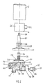
- the valve comprises a body 1 and a cap 2 mounted on the valve-body 1 so as to form a housing 3 ( Figure 1).
- a control-solenoid 4 is mounted on top of the housing 3.
- a cover 5 is also provided, being shown only in Figure 2. In the fully assembled condition of the valve, the cover 5 snaps into place over the solenoid 4.
- valve-body 1 and the cap 2 are made of brass by casting or by a combination of hot-pressing and machining operations and the externally exposed surfaces thereof have a chromium-plated finish.
- the valve-body 1 has an inlet port 11 for connection to a feed pipe of the heating system and an outlet port 12 for connection to a radiator of the system, the ports 11 and 12 being formed by internally screw-threaded bosses on the valve-body 1.
- the ports 11 and 12 communicate with passages 13 and 14 in the valve-body 1. (See Figure 2).
- valve-body 1 has an annular flange 15 formed with four threaded holes 16.
- the cap 2 has a flange 17 which, in the assembled condition of the valve shown in Figure 1, engages with the flange 15 on the valve-body 1 and the cap 2 is secured in position by bolts engaging in the holes 16 in the flange 15.
- a flow-chamber is formed within the cap 2 providing a flow-path for water flowing from the inlet port 11 to the outlet port 12 via passages 13 and 14.
- the valve-body 1 is machined to form a valve-seat 21.
- a diaphragm 22 is mounted within the cap 2.
- the diaphragm 22 and a backing disc 23 are carried by a shank 24 which forms the armature of solenoid 4.
- the energising coil of the solenoid 4 is not visible in the drawings, being inside solenoid casing 25.
- a compression spring 26 is mounted on shank 24.
- the shank 24 extends upwards through cap 2 and is a sliding fit into a sleeve 27.
- the sleeve 27 engages with cap 2 by mans of a screw-threaded collar 28, with the interposition of an O-ring 29.
- diaphragm 22 serves as a sealing gasket while at the same time, the central portion thereof can move as necessary.
- the sleeve 27 extends inside the solenoid-casing 25 and is retained in position by a nut 30 screwed on to a threaded stub 31 (see Figure 1).
- the diaphragm 22 is biassed into engagement with valve-seat 21 by the compression spring 26.
- the diaphragm 22 normally closes off the flow-path between passages 13 and 14 so as to maintain the valve in its shut-off condition.
- the valve is opened by actuating the solenoid 3 so as to lift diaphragm 22 out of engagement with valve-seat 21.
- the solenoid 4 is connected to the control circuit of the heating installation by means of wiring terminals 32 mounted on casing 25, so that the valve can be operated from a remote location, as herein described.
- the inlet passage 13 is the valve-body 1 communicates with the valve-seat 21 by way of a laterally extending portion 18 thereof.
- Inlet passage 13 also has an opening 19 for mounting a shut-off device 35 associated with passage 13.
- Shut-off device 35 comprises a screw-threaded member 36 which is tightly screwed into engagement in opening 19.
- a threaded spindle 37 passes through the member 36 and carries an obturating member constituted by a valve-disc 38.
- Two raised bosses are formed on either side of the valve-body 1. One of these bosses is visible at 41 in Figure 1. The other boss is formed at a corresponding position on the other side of the valve-body 1, which is not visible in Figure 1.
- boss 41 has been drilled to form a drain-port 42 to which is fitted a closure-plug 43.
- plug 43 is released by means of a spanner or key, to allow fluid to be discharged from the passage 14 to the exterior.
- valve-body 1 The corresponding boss at the other side of valve-body 1 is left blank, but the position at which a drain-port would be formed at this side of the valve body if required and the position of a corresponding closure plug are indicated by circle 44 in Figure 2.
- the port 11 in the position of the valve shown in Figure 1, the port 11 is arranged with its axis vertical while the axis of the port 12 is at right angles thereto.
- the valve can be fitted to a heating appliance either in the disposition shown in Figure 1, with the port 12 directed towards the left, or in the opposite disposition, with the port 12 directed towards the right, as the circumstances require.
- the valve selected for use in any particular case will have its drain-port 42 and closure-plug 43 at one side or the other of the valve-body, to suit the circumstances.
- shut-off device 35 of the valve fitted to this appliance is closed as previously described, in order to shut off the flow of fluid through the inlet passage 13, 18 of the valve.
- the closure plug 42 is then released, so that the limited quantity of fluid contained in the appliance can be drained away in a controlled manner, without any spillage. This can be done without interrupting the flow in the overall system, so as not to interrupt the heating of other rooms or areas served by the system.
- Valves in accordance with the invention can be constructed so that the dimensions of their pipe-connections correspond to those of existing standard valves. This enables the valves of an existing system to be replaced with valves in accordance with the invention, without any alteration to existing pipe-work and radiators. Moreover, the valve of the invention can be constructed so that it will function in any angular mounting position relative to the axis of the adjacent pipe-work.
- valve described above with reference to the drawings is primarily intended to be controlled from a remote location, such as from a manually operated central control panel, or automatically in accordance with a pre-stored operating programme.
- a valve may also be fitted with a thermostatic relay, so that it will also respond to changes in the local temperature where it is located.
- valve described is intended to facilitate shut-down for maintenance purposes, nevertheless, it is believed that the construction of the valve will be found to render the valve itself highly reliable in operation, and free of various defects which are found in existing valves. It has been found that with the arrangement of the diaphragm 22 as described, the valve operates in a reliable manner over a long period. Certain grades of nylon-reinforced nitrile rubber have been found to be very satisfactory for the manufacture of the diaphragm.
Landscapes
- Engineering & Computer Science (AREA)
- General Engineering & Computer Science (AREA)
- Mechanical Engineering (AREA)
- Physics & Mathematics (AREA)
- Thermal Sciences (AREA)
- Chemical & Material Sciences (AREA)
- Combustion & Propulsion (AREA)
- Electromagnetism (AREA)
- Magnetically Actuated Valves (AREA)
- Valve Housings (AREA)
Applications Claiming Priority (2)
| Application Number | Priority Date | Filing Date | Title |
|---|---|---|---|
| IE69890A IE61799B1 (en) | 1990-02-26 | 1990-02-26 | Improved control valve |
| IE69890 | 1990-02-27 |
Publications (1)
| Publication Number | Publication Date |
|---|---|
| EP0444879A1 true EP0444879A1 (de) | 1991-09-04 |
Family
ID=11016976
Family Applications (1)
| Application Number | Title | Priority Date | Filing Date |
|---|---|---|---|
| EP91301541A Withdrawn EP0444879A1 (de) | 1990-02-26 | 1991-02-26 | Regelventil |
Country Status (3)
| Country | Link |
|---|---|
| EP (1) | EP0444879A1 (de) |
| GB (1) | GB2242006B (de) |
| IE (1) | IE61799B1 (de) |
Cited By (1)
| Publication number | Priority date | Publication date | Assignee | Title |
|---|---|---|---|---|
| EP1205698A3 (de) * | 2000-11-09 | 2003-03-12 | Danfoss A/S | Ventil, insbesondere Heizkörperventil |
Families Citing this family (2)
| Publication number | Priority date | Publication date | Assignee | Title |
|---|---|---|---|---|
| DE20215891U1 (de) | 2002-10-16 | 2002-12-19 | AFRISO Euro-Index GmbH für Sicherungsarmaturen und Füllstandsmessung, 74363 Güglingen | Ventilanordnung für eine Fußbodenheizung |
| EP2063160A1 (de) | 2007-11-21 | 2009-05-27 | O'Reilly, Edward | Ventilbaugruppe und Steuerungssystem |
Citations (5)
| Publication number | Priority date | Publication date | Assignee | Title |
|---|---|---|---|---|
| CH532740A (de) * | 1970-12-14 | 1973-01-15 | Bortolan Lorenzo | Ventilaggregat, insbesondere für Heizungsanlagen |
| US3989222A (en) * | 1975-07-28 | 1976-11-02 | Fumiya Yoshiyasu | Solenoid valve |
| GB1547477A (en) * | 1977-03-21 | 1979-06-20 | Lucia R C | Radiator valve |
| GB1584252A (en) * | 1977-06-15 | 1981-02-11 | Watkins G D | Radiator control valves |
| GB2092715A (en) * | 1981-02-10 | 1982-08-18 | Midland Brass Fittings Co Ltd | Radiator valve |
-
1990
- 1990-02-26 IE IE69890A patent/IE61799B1/en not_active IP Right Cessation
-
1991
- 1991-02-26 GB GB9104029A patent/GB2242006B/en not_active Expired - Fee Related
- 1991-02-26 EP EP91301541A patent/EP0444879A1/de not_active Withdrawn
Patent Citations (5)
| Publication number | Priority date | Publication date | Assignee | Title |
|---|---|---|---|---|
| CH532740A (de) * | 1970-12-14 | 1973-01-15 | Bortolan Lorenzo | Ventilaggregat, insbesondere für Heizungsanlagen |
| US3989222A (en) * | 1975-07-28 | 1976-11-02 | Fumiya Yoshiyasu | Solenoid valve |
| GB1547477A (en) * | 1977-03-21 | 1979-06-20 | Lucia R C | Radiator valve |
| GB1584252A (en) * | 1977-06-15 | 1981-02-11 | Watkins G D | Radiator control valves |
| GB2092715A (en) * | 1981-02-10 | 1982-08-18 | Midland Brass Fittings Co Ltd | Radiator valve |
Cited By (1)
| Publication number | Priority date | Publication date | Assignee | Title |
|---|---|---|---|---|
| EP1205698A3 (de) * | 2000-11-09 | 2003-03-12 | Danfoss A/S | Ventil, insbesondere Heizkörperventil |
Also Published As
| Publication number | Publication date |
|---|---|
| GB9104029D0 (en) | 1991-04-10 |
| IE900698A1 (en) | 1991-08-28 |
| GB2242006B (en) | 1993-08-25 |
| GB2242006A (en) | 1991-09-18 |
| IE61799B1 (en) | 1994-11-30 |
Similar Documents
| Publication | Publication Date | Title |
|---|---|---|
| US3424189A (en) | Self-draining sill cock and vacuum breaker | |
| CA2170428C (en) | Ball valve with a strainer and integrated means for flushing the strainer | |
| US7198059B2 (en) | Apparatus and system for retrofitting water control valves | |
| US2936780A (en) | Combination solenoid valve and pressure switch | |
| US4633853A (en) | Hot water tank check valve | |
| WO1996029531A1 (en) | Valve actuating device of a heating and/or cooling system | |
| ATE300008T1 (de) | Ventil für ein wärmeträgersystem | |
| EP0568122B1 (de) | Ventilanordnung für Anlagen, die sowohl für Heizungs- als auch für Haushaltsheisswasser vorgesehen ist | |
| US4739793A (en) | Thermostatically operated valve | |
| US2966928A (en) | Fluid mixing devices | |
| EP0444879A1 (de) | Regelventil | |
| US4412648A (en) | Control valve assembly for steam radiators | |
| GB2229521A (en) | Central heating radiators | |
| GB2615187A (en) | Device for a valve system and use thereof | |
| DK174076B1 (da) | Reguleringsindsats til anbringelse i ventiler og ventilenhed | |
| US4925157A (en) | Solenoid-operated control apparatus | |
| US4084611A (en) | Single-handle mixing valve | |
| KR102529601B1 (ko) | 유량조절밸브 및 이를 포함하는 난방 온수 분배기 | |
| US3779278A (en) | Faucet | |
| KR102057399B1 (ko) | 유량조절밸브 조립체 | |
| SE502584C2 (sv) | Shuntventilanordningar | |
| US9423036B1 (en) | Thermostatic radiator valve insert | |
| JPH0211667Y2 (de) | ||
| JP2912387B2 (ja) | 流体漏洩検知機構内蔵弁 | |
| KR200357844Y1 (ko) | 온도조절 구동장치작동 밸브 |
Legal Events
| Date | Code | Title | Description |
|---|---|---|---|
| PUAI | Public reference made under article 153(3) epc to a published international application that has entered the european phase |
Free format text: ORIGINAL CODE: 0009012 |
|
| AK | Designated contracting states |
Kind code of ref document: A1 Designated state(s): AT BE CH DE DK ES FR GB GR IT LI LU NL SE |
|
| 17P | Request for examination filed |
Effective date: 19920302 |
|
| 17Q | First examination report despatched |
Effective date: 19940422 |
|
| RBV | Designated contracting states (corrected) |
Designated state(s): AT BE CH DE DK ES FR GR IT LI LU NL SE |
|
| STAA | Information on the status of an ep patent application or granted ep patent |
Free format text: STATUS: THE APPLICATION IS DEEMED TO BE WITHDRAWN |
|
| 18D | Application deemed to be withdrawn |
Effective date: 19950808 |