EP0444518A2 - Système pour réguler une machine à champ tournant commandée par onduleur d'impulsion - Google Patents
Système pour réguler une machine à champ tournant commandée par onduleur d'impulsion Download PDFInfo
- Publication number
- EP0444518A2 EP0444518A2 EP91102471A EP91102471A EP0444518A2 EP 0444518 A2 EP0444518 A2 EP 0444518A2 EP 91102471 A EP91102471 A EP 91102471A EP 91102471 A EP91102471 A EP 91102471A EP 0444518 A2 EP0444518 A2 EP 0444518A2
- Authority
- EP
- European Patent Office
- Prior art keywords
- pulse
- inverter
- voltage
- vector
- control system
- Prior art date
- Legal status (The legal status is an assumption and is not a legal conclusion. Google has not performed a legal analysis and makes no representation as to the accuracy of the status listed.)
- Granted
Links
Images


Classifications
-
- H—ELECTRICITY
- H02—GENERATION; CONVERSION OR DISTRIBUTION OF ELECTRIC POWER
- H02P—CONTROL OR REGULATION OF ELECTRIC MOTORS, ELECTRIC GENERATORS OR DYNAMO-ELECTRIC CONVERTERS; CONTROLLING TRANSFORMERS, REACTORS OR CHOKE COILS
- H02P21/00—Arrangements or methods for the control of electric machines by vector control, e.g. by control of field orientation
- H02P21/06—Rotor flux based control involving the use of rotor position or rotor speed sensors
- H02P21/10—Direct field-oriented control; Rotor flux feed-back control
-
- H—ELECTRICITY
- H02—GENERATION; CONVERSION OR DISTRIBUTION OF ELECTRIC POWER
- H02P—CONTROL OR REGULATION OF ELECTRIC MOTORS, ELECTRIC GENERATORS OR DYNAMO-ELECTRIC CONVERTERS; CONTROLLING TRANSFORMERS, REACTORS OR CHOKE COILS
- H02P27/00—Arrangements or methods for the control of AC motors characterised by the kind of supply voltage
- H02P27/04—Arrangements or methods for the control of AC motors characterised by the kind of supply voltage using variable-frequency supply voltage, e.g. inverter or converter supply voltage
- H02P27/06—Arrangements or methods for the control of AC motors characterised by the kind of supply voltage using variable-frequency supply voltage, e.g. inverter or converter supply voltage using DC to AC converters or inverters
-
- H—ELECTRICITY
- H02—GENERATION; CONVERSION OR DISTRIBUTION OF ELECTRIC POWER
- H02P—CONTROL OR REGULATION OF ELECTRIC MOTORS, ELECTRIC GENERATORS OR DYNAMO-ELECTRIC CONVERTERS; CONTROLLING TRANSFORMERS, REACTORS OR CHOKE COILS
- H02P27/00—Arrangements or methods for the control of AC motors characterised by the kind of supply voltage
- H02P27/04—Arrangements or methods for the control of AC motors characterised by the kind of supply voltage using variable-frequency supply voltage, e.g. inverter or converter supply voltage
- H02P27/047—V/F converter, wherein the voltage is controlled proportionally with the frequency
Definitions
- the invention relates to a control system for a pulse-controlled inverter induction machine according to the preamble of claim 1.
- a voltage generator for generating a suitable control of the pulse-controlled inverter is usually generated by a pulse generator such that the desired fundamental vibration and the lowest possible harmonics occur when the pulse-controlled inverter switches function correctly.
- a pulse generator such that the desired fundamental vibration and the lowest possible harmonics occur when the pulse-controlled inverter switches function correctly.
- large errors can occur in some operating areas due to non-ideal behavior of the inverter switches.
- the inverter switches and the associated control circuits have time delays.
- a control system for a pulse-inverter-controlled induction machine is known from the dissertation "The method for controlling the pulse-converter-fed asynchronous machine by prediction and optimization in real time” by Siegfried Stadtfeld, Department of Electrical Engineering at Bergische Vietnamese - GH Wuppertal, 1987.
- this known control system works on a current basis, not on a voltage basis.
- the target current to be specified can only be determined with difficulty. It is also dependent on the overall system and in particular on the induction machine.
- the object of the invention is to provide a control system for a pulse inverter controlled induction machine according to the preamble of claim 1, with which errors in the pulse inverter and in the DC voltage predetermined for the pulse inverter can be completely corrected.
- this object is achieved by the features specified in the characterizing part of claim 1. Not the motor current but the motor voltage is used as the setpoint.
- the vectorial difference between the target voltage vector and the actual voltage vector is formed in the pulse generator. This vectorial difference is then integrated.
- the result of this integration that is to say the integrated difference vector, is used to influence the switching states of the pulse-controlled inverter.
- the integration and evaluation of the actually existing voltage difference between the target voltage and the actually existing measured actual voltage ensures that the actual voltage vector is actually simulated over time on average.
- the errors in the pulse inverter and - if present - in the DC voltage specified for the pulse inverter by, for example, a line rectifier, are automatically corrected.
- setpoint voltage value is also integrated with the voltage difference
- setpoint jumps can also be corrected without any problems.
- the disadvantages of the known, only corrective methods are avoided. According to these known, correcting methods, the error in the motor voltage by the pulse inverter or the non-ideal DC input voltage of the pulse inverter in certain operating states of the induction machine and / or the pulse inverter, for example in the event of zero current crossing, can only be compensated to a limited extent, although in these Good compensation would be very important.
- These errors are corrected by the integration of the difference vector between the target voltage vector and the actual voltage vector, that is, they are compensated for to the best possible extent. Nevertheless, relatively high target or actual voltages can still be processed with the control system according to the invention.
- the theoretical maximum of the ratio of the processable target and actual voltages to the supply voltage is 1.1: J2 fundamental).
- a ratio of the nominal or actual voltages to the supply voltage of up to 1.0: / 2 can be achieved with full modulation capability, and beyond that if there is no sine-weighted modulation.
- the actual voltage genuinely physically generated on the induction machine that is to say the input voltage of the induction machine, is vectorially recorded and compared with the predetermined target voltage.
- the average deviation between the target voltage and the actual voltage is fed to the control system.
- any time profiles of the target voltage vector are quickly taken into account and time errors in the switching function are compensated for, as are rapid changes in the DC voltage which feeds the pulse-controlled inverter and which, for example, comes from the DC link of a converter.
- Chen a non-equidistant switching pattern is generated, so that disturbing single tones hardly occur in the engine.
- the integrated difference vector preferably the amount of the integrated difference vector
- a limit value if, depending on this comparison, a new switching state is determined and forwarded to the pulse-controlled inverter.
- a surface that e.g. based on this vector can be used.
- the new switching state is preferably determined as a function of the target voltage vector and the integrated difference vector, the switching state preferably being changed so that the difference vector is reduced as a result of this switching action.
- the limit value is preferably determined as a function of the integrated target voltage vector.
- the limit value is therefore not given the same for all operating states, but is tracked as a function of the target voltage vector.
- the control system can also be adapted to different operating states.
- a further advantageous development is characterized by a rectifier fed with multiphase alternating voltage, preferably three-phase voltage, and a DC intermediate circuit fed by the rectifier and feeding the pulse-controlled inverter.
- the induction machine is therefore controlled by a converter consisting of a rectifier, a DC link and a pulse inverter.
- the switching state is determined by the pulse generator so that it can be maintained as long as possible.
- the switching frequency can be minimized.
- the outlay, in particular the outlay on circuitry, for the pulse-controlled inverter is thereby reduced and the efficiency is improved.
- the switching frequency of the pulse inverter can be reduced with the same ripple. The switching losses can be minimized in this way.
- the vectorial integration is preferably carried out analogously.
- Digital integration would lead to higher costs due to the high processing speed required. It is therefore advantageous to implement the integration analogously.
- the disadvantage of having to convert the setpoint from digital to analog is hardly significant.
- the result of the integration is preferably digitized and digitally processed.
- the digitization of the result of the integration is not critical in terms of timing, since the integration already results in a smoothed signal.
- the rate of change of the output signal of the integrator is relatively slow due to this smoothing.
- the accuracy at this point in the overall system is not critical.
- a new switching state is preferably read out of a memory, that is to say it is not - which is also possible - calculated in real time.
- the new switching state is read out of the memory depending on the current sizes specified above.
- DE-PS 34 38 504 discloses a method for controlling a three-phase machine, which is fed via an inverter with an impressed input DC voltage, with the following steps: forming an actual flow value, comparing the actual flow value with a desired flow value, forming an first control vector with a number of discrete positions, which are cyclically run through, corresponding to the pulse number of the inverter, switching the first control vector to the next discrete position when the actual flow value exceeds the desired flow value. So that a smooth transition is possible even with rapid changes in the flow setpoint, the component of the actual flow space pointer perpendicular to the direction of the discrete position that is to be assumed by the first control vector is used as the actual flow value.
- the flow in vector representation room pointer representation
- the invention provides a control system for a three-phase machine fed by pulse inverters, preferably an asynchronous machine, with a pulse generator for controlling the switching state of the pulse inverter and with a machine control for specifying target voltages for the pulse generator, the output voltages of the pulse inverter being measured and the pulse generator as the actual instantaneous switching state Corresponding actual voltages are supplied to the pulse-controlled inverter, the difference between the target voltages and the actual voltages being formed in the pulse generator, this difference then being integrated and the result of this integration being used to influence the switching states of the pulse-controlled inverter.
- the difference formation and integration takes place vectorially; if the position of the integrated difference vector in an evaluation circuit is checked with respect to a predetermined tolerance area, the evaluation circuit emits a switching signal when the integrated difference vector reaches the edge of the tolerance area , starting from the point of penetration of the difference vector through the edge of the tolerance area, the paths to be expected for all possible pulse inverter switching states and the next point of penetration for the integrated difference vector are determined, the expected dwell time in the tolerance area is determined for all pulse inverter switching states and a switching state, preferably the switching state with the longest expected dwell time, is selected.
- the amount of the integrated difference vector is preferably compared in the evaluation circuit with the radius of a circular tolerance area. More preferably, the switching state with the longest dwell time is determined in advance for each possible puncture point, read into a memory and read out during operation when the respective puncture point is reached.
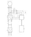
- the control system shown in FIG. 1 for a pulse inverter controlled induction machine consists of the three-phase asynchronous motor 1, the pulse inverter 2, the pulse generator 3 and the machine guide 4.
- the three-phase asynchronous motor 1 is controlled by specifying a voltage vector.
- the pulse inverter 2 feeds the asynchronous motor 1.
- the switching state of the pulse inverter 2 is controlled by the pulse generator 3.
- the machine guide 4 specifies a target voltage vector for the pulse generator 3.
- the output voltages of the pulse inverter 2 and thus the input voltages of the asynchronous motor 1 are measured as instantaneous values and are fed through the feedback 5 to the pulse generator 3 as actual voltages corresponding to the actual switching states of the pulse inverter 2, from which the actual voltage vector is formed.
- the instantaneous output voltages of the pulse inverter 2 are therefore taken into account or used in the pulse generator 3.
- the pulse inverter 2 is part of a converter, consisting of rectifier 6, DC voltage intermediate circuit 7 and pulse inverter 2.
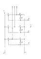
- FIG. 2 shows the basic circuit diagram of the pulse inverter 2.
- the (non-ideal) DC voltage present at the input terminals 8, 9 is converted into a the three-phase three-phase voltage applied to the output terminals U2, V2 and W2.
- the inverter switches 10 - 15 are used for this purpose and are switched in pairs in opposite directions.
- the inverting elements 16 connected upstream of the switches 13 to 15 are used for this purpose.
- the switching state of the pulse-controlled inverter is specified via the binary signals ZU, ZV and ZW.
- the 3 shows the signal flow diagram of the pulse generator 3.
- the three measured instantaneous voltages of the three-phase system are specified at the input terminals U1, V1 and W1.
- the voltage values U1, V1 and W1 correspond to the output voltages U2, V2 and W2 of the pulse-controlled inverter.
- the target voltage vector of the machine guide 4 is represented by Usolla and Usollß.
- the 3/2 coordinate converter 17 converts the three-phase actual voltage U1, V1 and W1 into an actual voltage vector Uist ⁇ , Uistß consisting of two components.
- the difference between the components of the target voltage vector and the actual voltage vector is formed on the two subtractors 18, 19; there by means of vectorial subtraction.
- the vectorial difference between the target voltage vector and the actual voltage vector is then vectorially integrated in the integrators 20, 21. This creates the vector , represented by ⁇ and ⁇ . Because the vector from an integration of the tension over time, it can be interpreted as a "flow vector".
- the "flux vector” vector of the voltage time area
- ⁇ , ⁇ vector of the voltage time area
- the amount of the "flow vector” / / and phase 0 of the "flow vector” are fed to the comparator 23.
- Phase 5 of the river vector is also fed to the computing element 24.
- the target voltage vector Usoll ⁇ , Usollß also goes into the computing element 24.
- the "flow vector” vector of the voltage time area
- this limit value R consists of its components / R / and Rphase.
- the comparator 23 sends a signal to the computing element 24, on the basis of which the computing algorithm present in the computing element determines a new switching pattern Zu, Zv, Zw, that is to say a new successor pointer.
- a new limit value can be generated by the computing element 24 calculated and given to the comparator 23.
- the result of the integration in the integrators 20, 21, namely the integrated difference vector, is therefore used to influence the switching states of the pulse-controlled inverter.
- the switching state of the pulse-controlled inverter is dependent on the target voltage vector Usoll ⁇ , Usollß and the integrated difference vector ⁇ , ⁇ and / /, ⁇ determined.
- the switching state for the pulse inverter 2 is determined by the pulse generator 3 or its computing element 24 in such a way that it can be maintained for as long as possible.
- FIG. 4 shows the voltage vectors possible with the three-phase pulse inverter shown in FIG. 2, assuming an ideal DC voltage at the input of the pulse inverter and its ideal function. 2 has eight switching states, so that eight voltage vectors are possible.
- the first voltage vector lies on the ⁇ axis, the following five voltage vectors are rotated by the same amount by 60 ° each.
- the two other possible voltage vectors are zero vectors in the coordinate origin. Any voltage vector 0 can be achieved on average over time by pulsing the eight basic vectors.
- FIG. 5 shows a trajectory of the "flow vector” (or vector of the voltage time area) within the tolerance area, which is represented here by a circle with the radius / / is shown.
- the switching state of the pulse inverter 2 is determined by the pulse generator 3 in such a way that it can be maintained as long as possible until the "flow vector" again leaves the tolerance area.
- FIG. 6 shows a block diagram of the pulse generator.
- the part 26 of FIG. 6 delimited by a dash-dotted line 25 essentially corresponds to the representation of FIG. 3.
- the arithmetic element 24 is delimited by the dash-dotted line 27. It consists of a coordinate converter a for converting cathesic to polar coordinates, a comparator b, a readout logic c for the optimal successor pointer, a register d and a converter e for converting frequency into phase angle.
- the pulse generator is used to generate a three-phase pulse width modulated voltage (three-phase system). He works as a real-time control system, i.e. it compares the specified target voltage with the actual voltage value.
- the specified setpoint which normally consists of a sinusoidal voltage, must be generated by alternately switching on the various space pointers on average over time.
- the modulator described forms the space pointer of the voltage-time area from the difference between the setpoint and actual voltage (this space pointer is always referred to below as the difference space pointer). This is done by separate integration of the ⁇ and ⁇ components in the integrators 20, 21.
- the control system monitors the determined voltage time area for a limit value. With a circular tolerance area, a circle forms a direction-independent limit for the room pointer. When the tolerance area is left, the control system specifies new control pulses for the pulse-controlled inverter in such a way that the voltage changes due to the set new actual pointer reduced space. The control pulses are thus predetermined so that the differential space pointer moves in the direction of the center of the tolerance circle.
- the integrator described Since the integrator described is at no time influenced by variables other than the setpoint or the actual value, it is ensured that the deviation between the setpoint and actual value is zero on average over time.
- the size of the tolerance area determines the maximum short-term tolerated deviation and thus determines the mean clock frequency. By choosing the size of the tolerance area, the desired compromise between high control accuracy and low switching frequency can be achieved.
- the difference space pointers for the seven possible successor pointers are calculated, starting from the intersection point. This means that the new expected penetration points can be calculated in advance through the tolerance area and the times required for this, i.e. the dwell times. For this calculation, the setpoint is considered constant during this time. This assumption is of course only correct if the actual change in the target pointer is negligible. This is the case if the clock frequency is approximately 10 times greater than the frequency of the setpoint. This condition applies to pulse inverters in the scope of this method. If necessary, the expected change in the target pointer could also be included in the calculation without effort.
- the successor pointer that gives the longest dwell time and that can be reached with the smallest number of switchovers in the inverter from the current actual state is considered and selected as the optimal successor pointer.
- the pulse modulator can be divided into an analog part and a digital part.
- the analog part takes over the recording of the actual voltage, the comparison of the setpoint and actual value and the formation of the difference space pointer.
- the optimum successor pointer is determined in the downstream digital part.
- the conductor voltages UV and VW are formed from the three voltage potentials of the inverter U, V, W using two differential measurements A.
- these and ⁇ components of the voltage actual pointer Uista, Uistß are formed.
- These two components are each compared with the corresponding component of the setpoint Usolla, Usollß.
- the result of this comparison is integrated vectorially, i.e. separately.
- the output signals of the two integrators correspond to the a and ⁇ components of the difference space vector ⁇ , ⁇ .
- Harmonic analyzes of the voltage and the motor current show a distribution of the harmonics over a large frequency range.
- the range of the motor current is between 800 Hz and 2,500 Hz with an average clock frequency of approximately 1,200 Hz.
- There are no individual harmonics with a relatively large amplitude e.g. clock frequency that occurs with asynchronous or synchronous pulse patterns). This results in noise as engine noise, which subjectively is perceived as much more pleasant than the whistle of an asynchronous or synchronous pulse pattern.
- the average clock frequency can be kept approximately constant over a wide voltage range (approx. 20% from UN to 100% from UN) by suitable adjustment of the tolerance circle. With lower output voltages, the clock frequency is reduced (at approx. 2% of UN approx. 150 Hz with approx. 50 microseconds dead time in the inverter). However, this does not result in an uncomfortably loud noise or irregular engine running.
- the frequency and amplitude can be set freely within certain limits.
- abrupt changes in the phase angle or the amplitude can be implemented without any problems, since for the time being “only” the integration speeds of the two integrators are changed. On the one hand, this results in an immediate reaction to the new setpoint, but on the other hand there is no uncontrolled change in the control pulses.
- the modulator With a suitable machine control, the modulator also appears to be well suited for dynamic, high-quality control.
Landscapes
- Engineering & Computer Science (AREA)
- Power Engineering (AREA)
- Inverter Devices (AREA)
- Control Of Ac Motors In General (AREA)
- General Induction Heating (AREA)
- Control Of Multiple Motors (AREA)
- Control Of Eletrric Generators (AREA)
Applications Claiming Priority (2)
| Application Number | Priority Date | Filing Date | Title |
|---|---|---|---|
| DE4006447 | 1990-03-01 | ||
| DE19904006447 DE4006447A1 (de) | 1990-03-01 | 1990-03-01 | Regelsystem fuer eine pulswechselrichtergesteuerte drehfeldmaschine |
Publications (3)
| Publication Number | Publication Date |
|---|---|
| EP0444518A2 true EP0444518A2 (fr) | 1991-09-04 |
| EP0444518A3 EP0444518A3 (en) | 1991-11-13 |
| EP0444518B1 EP0444518B1 (fr) | 1994-09-28 |
Family
ID=6401210
Family Applications (1)
| Application Number | Title | Priority Date | Filing Date |
|---|---|---|---|
| EP19910102471 Expired - Lifetime EP0444518B1 (fr) | 1990-03-01 | 1991-02-20 | Système pour réguler une machine à champ tournant commandée par onduleur d'impulsion |
Country Status (3)
| Country | Link |
|---|---|
| EP (1) | EP0444518B1 (fr) |
| AT (1) | ATE112431T1 (fr) |
| DE (2) | DE4006447A1 (fr) |
Cited By (2)
| Publication number | Priority date | Publication date | Assignee | Title |
|---|---|---|---|---|
| EP0574322A1 (fr) * | 1992-06-12 | 1993-12-15 | Schneider Electric Sa | Procédé de commande d'un onduleur de tension polyphasé à modulation de largeur d'impulsions et dispositif pour la mise en oeuvre de ce procédé |
| CN112886899A (zh) * | 2021-01-15 | 2021-06-01 | 湖南大学 | 一种n*3相永磁同步电机绕组单元自控制方法与装置 |
Families Citing this family (1)
| Publication number | Priority date | Publication date | Assignee | Title |
|---|---|---|---|---|
| DE102011056493A1 (de) * | 2011-02-15 | 2012-08-16 | Zf Lenksysteme Gmbh | Verfahren zur ansteuerung eines elektromotors einer hilfs-oder fremdkraftlenkung eines kraftfahrzeugs |
Family Cites Families (3)
| Publication number | Priority date | Publication date | Assignee | Title |
|---|---|---|---|---|
| DE2754241A1 (de) * | 1977-12-06 | 1979-06-07 | Jutronik Gmbh | Statischer frequenzumformer nach dem gleichstrom-zwischenkreis-prinzip zur speisung von drehstrommotoren |
| JPS5953800B2 (ja) * | 1980-12-18 | 1984-12-26 | 富士電機株式会社 | 交流電動機の制御装置 |
| DE3438504A1 (de) * | 1984-10-20 | 1986-04-24 | Brown, Boveri & Cie Ag, 6800 Mannheim | Verfahren und einrichtung zur regelung einer drehfeldmaschine |
-
1990
- 1990-03-01 DE DE19904006447 patent/DE4006447A1/de active Granted
-
1991
- 1991-02-20 EP EP19910102471 patent/EP0444518B1/fr not_active Expired - Lifetime
- 1991-02-20 AT AT91102471T patent/ATE112431T1/de not_active IP Right Cessation
- 1991-02-20 DE DE59103070T patent/DE59103070D1/de not_active Expired - Fee Related
Cited By (3)
| Publication number | Priority date | Publication date | Assignee | Title |
|---|---|---|---|---|
| EP0574322A1 (fr) * | 1992-06-12 | 1993-12-15 | Schneider Electric Sa | Procédé de commande d'un onduleur de tension polyphasé à modulation de largeur d'impulsions et dispositif pour la mise en oeuvre de ce procédé |
| FR2692416A1 (fr) * | 1992-06-12 | 1993-12-17 | Telemecanique | Procédé de commande d'un onduleur de tension polyphasé à modulation de largeur d'impulsions et dispositif pour la mise en Óoeuvre de ce procédé. |
| CN112886899A (zh) * | 2021-01-15 | 2021-06-01 | 湖南大学 | 一种n*3相永磁同步电机绕组单元自控制方法与装置 |
Also Published As
| Publication number | Publication date |
|---|---|
| DE59103070D1 (de) | 1994-11-03 |
| DE4006447C2 (fr) | 1992-07-30 |
| EP0444518B1 (fr) | 1994-09-28 |
| DE4006447A1 (de) | 1991-09-05 |
| ATE112431T1 (de) | 1994-10-15 |
| EP0444518A3 (en) | 1991-11-13 |
Similar Documents
| Publication | Publication Date | Title |
|---|---|---|
| EP1652289B1 (fr) | Procede pour appliquer de maniere commandee une valeur theorique de courant rotorique ou de couple de rotation pour un generateur a induction alimente par convertisseur | |
| DE69932980T2 (de) | Resolversignalverarbeitungssystem | |
| DE3816444C2 (fr) | ||
| DE102012107970B4 (de) | Steuervorrichtung für eine drehende elektrische Maschine | |
| EP0161615B1 (fr) | Méthode et dispositif pour définir le vecteur de flux d'une machine à champ tournant | |
| DE69130809T2 (de) | Vorrichtung zur Erzeugung eines dreiphasigen PWM-Signals für Wechselrichter | |
| DE69317392T2 (de) | Abtastfrequenzumwandler | |
| DE69606103T2 (de) | Verfahren zur Steuerung des Stroms eines Servomotors | |
| DE4426764C2 (de) | Verfahren zur Ansteuerung eines Pulswechselrichters durch Stellbefehle eines Pulsmustergenerators | |
| EP0884834B1 (fr) | Procédé et dispositif pour la régulation de courant d'un moteur synchrone à aimant permanent et à f.e.m. trapézoidale et commandé par champ orienté | |
| DE68916684T2 (de) | Pulsbreitenmodulierungssteuereinheit für Wechselrichter. | |
| EP0444518B1 (fr) | Système pour réguler une machine à champ tournant commandée par onduleur d'impulsion | |
| DE69919528T2 (de) | Regelverfahren und vorrichtung für einen statischen, eine spannungsquelle speisenden wandler | |
| EP0298290B1 (fr) | Méthode et appareil pour faire fonctionner un générateur à induction | |
| DE69315818T2 (de) | Regelungsverfahren für einen wechselstrommotor | |
| EP0474629B1 (fr) | Procede de compensation d'une reponse phase et d'une caracteristique d'amplitude entre une valeur de consigne et une valeur reelle polyphasees, et circuit pour la mise en oeuvre de ce procede | |
| WO2018072791A1 (fr) | Procédé et circuit pour commander un moteur pas à pas | |
| DE3332567C2 (de) | Anordnung zur Regelung einer durch schnelle elektrische Stellglieder gespeisten Asynchronmaschine in der Feldschwächung | |
| DE19947128A1 (de) | PWM-Stromrichter | |
| DE112018005734T5 (de) | Motorsteuervorrichtung und Motorsteuerverfahren | |
| DE2705343C2 (de) | Steuerverfahren für einen selbstgeführten, pulsgesteuerten Wechselrichter und Steueranordnung zur Bildung der Sollwerte für die Pulssteuerung | |
| EP0504449B1 (fr) | Méthode et dispositif pour la production des signaux de commutation à partir d'un vecteur tension de contrôle | |
| DE2739918C2 (de) | Stromrichteranordnung | |
| DE3026348A1 (de) | Schaltungsanordnung zur bildung eines elektrischen spannungssignals, das einer flusskomponente in einer drehfeldmaschine proportional ist | |
| DE19640591C1 (de) | Verfahren zur Drehmomentregelung einer Drehfeldmaschine |
Legal Events
| Date | Code | Title | Description |
|---|---|---|---|
| PUAI | Public reference made under article 153(3) epc to a published international application that has entered the european phase |
Free format text: ORIGINAL CODE: 0009012 |
|
| AK | Designated contracting states |
Kind code of ref document: A2 Designated state(s): AT CH DE GB LI NL |
|
| PUAL | Search report despatched |
Free format text: ORIGINAL CODE: 0009013 |
|
| RHK1 | Main classification (correction) |
Ipc: H02P 7/628 |
|
| AK | Designated contracting states |
Kind code of ref document: A3 Designated state(s): AT CH DE GB LI NL |
|
| 17P | Request for examination filed |
Effective date: 19920319 |
|
| 17Q | First examination report despatched |
Effective date: 19940225 |
|
| GRAA | (expected) grant |
Free format text: ORIGINAL CODE: 0009210 |
|
| AK | Designated contracting states |
Kind code of ref document: B1 Designated state(s): AT CH DE GB LI NL |
|
| REF | Corresponds to: |
Ref document number: 112431 Country of ref document: AT Date of ref document: 19941015 Kind code of ref document: T |
|
| REF | Corresponds to: |
Ref document number: 59103070 Country of ref document: DE Date of ref document: 19941103 |
|
| GBT | Gb: translation of ep patent filed (gb section 77(6)(a)/1977) |
Effective date: 19941101 |
|
| PLBE | No opposition filed within time limit |
Free format text: ORIGINAL CODE: 0009261 |
|
| STAA | Information on the status of an ep patent application or granted ep patent |
Free format text: STATUS: NO OPPOSITION FILED WITHIN TIME LIMIT |
|
| 26N | No opposition filed | ||
| PGFP | Annual fee paid to national office [announced via postgrant information from national office to epo] |
Ref country code: NL Payment date: 20000223 Year of fee payment: 10 |
|
| PGFP | Annual fee paid to national office [announced via postgrant information from national office to epo] |
Ref country code: CH Payment date: 20000228 Year of fee payment: 10 |
|
| PG25 | Lapsed in a contracting state [announced via postgrant information from national office to epo] |
Ref country code: LI Free format text: LAPSE BECAUSE OF NON-PAYMENT OF DUE FEES Effective date: 20010228 Ref country code: CH Free format text: LAPSE BECAUSE OF NON-PAYMENT OF DUE FEES Effective date: 20010228 |
|
| PG25 | Lapsed in a contracting state [announced via postgrant information from national office to epo] |
Ref country code: NL Free format text: LAPSE BECAUSE OF NON-PAYMENT OF DUE FEES Effective date: 20010901 |
|
| REG | Reference to a national code |
Ref country code: CH Ref legal event code: PL |
|
| NLV4 | Nl: lapsed or anulled due to non-payment of the annual fee |
Effective date: 20010901 |
|
| REG | Reference to a national code |
Ref country code: GB Ref legal event code: IF02 |
|
| PGFP | Annual fee paid to national office [announced via postgrant information from national office to epo] |
Ref country code: GB Payment date: 20050124 Year of fee payment: 15 |
|
| PGFP | Annual fee paid to national office [announced via postgrant information from national office to epo] |
Ref country code: AT Payment date: 20050218 Year of fee payment: 15 |
|
| PGFP | Annual fee paid to national office [announced via postgrant information from national office to epo] |
Ref country code: DE Payment date: 20050225 Year of fee payment: 15 |
|
| PG25 | Lapsed in a contracting state [announced via postgrant information from national office to epo] |
Ref country code: GB Free format text: LAPSE BECAUSE OF NON-PAYMENT OF DUE FEES Effective date: 20060220 Ref country code: AT Free format text: LAPSE BECAUSE OF NON-PAYMENT OF DUE FEES Effective date: 20060220 |
|
| PG25 | Lapsed in a contracting state [announced via postgrant information from national office to epo] |
Ref country code: DE Free format text: LAPSE BECAUSE OF NON-PAYMENT OF DUE FEES Effective date: 20060901 |
|
| GBPC | Gb: european patent ceased through non-payment of renewal fee |
Effective date: 20060220 |