EP0443904A1 - Greifer für das Heben und die Handhabung eines Gegenstandes zwischen eine in einer heissen Flüssigkeit -z.B. einem Metall- getauchte Stellung und eine in einem Gas aufgetauchte Stellung - Google Patents
Greifer für das Heben und die Handhabung eines Gegenstandes zwischen eine in einer heissen Flüssigkeit -z.B. einem Metall- getauchte Stellung und eine in einem Gas aufgetauchte Stellung Download PDFInfo
- Publication number
- EP0443904A1 EP0443904A1 EP91400327A EP91400327A EP0443904A1 EP 0443904 A1 EP0443904 A1 EP 0443904A1 EP 91400327 A EP91400327 A EP 91400327A EP 91400327 A EP91400327 A EP 91400327A EP 0443904 A1 EP0443904 A1 EP 0443904A1
- Authority
- EP
- European Patent Office
- Prior art keywords
- slide
- tubular body
- grapple
- bell
- liquid metal
- Prior art date
- Legal status (The legal status is an assumption and is not a legal conclusion. Google has not performed a legal analysis and makes no representation as to the accuracy of the status listed.)
- Withdrawn
Links
- 239000007788 liquid Substances 0.000 title claims description 18
- 229910052751 metal Inorganic materials 0.000 title claims description 6
- 239000002184 metal Substances 0.000 title claims description 6
- 229910001338 liquidmetal Inorganic materials 0.000 claims abstract description 55
- 239000000446 fuel Substances 0.000 claims description 22
- 239000007789 gas Substances 0.000 claims description 13
- DGAQECJNVWCQMB-PUAWFVPOSA-M Ilexoside XXIX Chemical compound C[C@@H]1CC[C@@]2(CC[C@@]3(C(=CC[C@H]4[C@]3(CC[C@@H]5[C@@]4(CC[C@@H](C5(C)C)OS(=O)(=O)[O-])C)C)[C@@H]2[C@]1(C)O)C)C(=O)O[C@H]6[C@@H]([C@H]([C@@H]([C@H](O6)CO)O)O)O.[Na+] DGAQECJNVWCQMB-PUAWFVPOSA-M 0.000 claims description 12
- 238000000429 assembly Methods 0.000 claims description 12
- 230000000712 assembly Effects 0.000 claims description 12
- 229910052708 sodium Inorganic materials 0.000 claims description 12
- 239000011734 sodium Substances 0.000 claims description 12
- 238000007664 blowing Methods 0.000 claims description 4
- 239000000112 cooling gas Substances 0.000 claims description 4
- 238000007711 solidification Methods 0.000 description 6
- 230000008023 solidification Effects 0.000 description 6
- 238000007710 freezing Methods 0.000 description 5
- 230000008014 freezing Effects 0.000 description 5
- XKRFYHLGVUSROY-UHFFFAOYSA-N Argon Chemical compound [Ar] XKRFYHLGVUSROY-UHFFFAOYSA-N 0.000 description 4
- 238000006073 displacement reaction Methods 0.000 description 4
- 239000011261 inert gas Substances 0.000 description 3
- 229910052786 argon Inorganic materials 0.000 description 2
- 239000002826 coolant Substances 0.000 description 2
- 150000003839 salts Chemical class 0.000 description 2
- 238000003466 welding Methods 0.000 description 2
- QVGXLLKOCUKJST-UHFFFAOYSA-N atomic oxygen Chemical compound [O] QVGXLLKOCUKJST-UHFFFAOYSA-N 0.000 description 1
- 210000000078 claw Anatomy 0.000 description 1
- 238000001816 cooling Methods 0.000 description 1
- 238000000151 deposition Methods 0.000 description 1
- 230000000694 effects Effects 0.000 description 1
- 230000005484 gravity Effects 0.000 description 1
- 238000009434 installation Methods 0.000 description 1
- 230000003993 interaction Effects 0.000 description 1
- 238000000034 method Methods 0.000 description 1
- 239000001301 oxygen Substances 0.000 description 1
- 229910052760 oxygen Inorganic materials 0.000 description 1
- 230000000717 retained effect Effects 0.000 description 1
- 239000007787 solid Substances 0.000 description 1
- 229910001220 stainless steel Inorganic materials 0.000 description 1
- 239000010935 stainless steel Substances 0.000 description 1
- 238000003860 storage Methods 0.000 description 1
Images

Classifications
-
- G—PHYSICS
- G21—NUCLEAR PHYSICS; NUCLEAR ENGINEERING
- G21C—NUCLEAR REACTORS
- G21C19/00—Arrangements for treating, for handling, or for facilitating the handling of, fuel or other materials which are used within the reactor, e.g. within its pressure vessel
- G21C19/02—Details of handling arrangements
- G21C19/10—Lifting devices or pulling devices adapted for co-operation with fuel elements or with control elements
- G21C19/105—Lifting devices or pulling devices adapted for co-operation with fuel elements or with control elements with grasping or spreading coupling elements
-
- Y—GENERAL TAGGING OF NEW TECHNOLOGICAL DEVELOPMENTS; GENERAL TAGGING OF CROSS-SECTIONAL TECHNOLOGIES SPANNING OVER SEVERAL SECTIONS OF THE IPC; TECHNICAL SUBJECTS COVERED BY FORMER USPC CROSS-REFERENCE ART COLLECTIONS [XRACs] AND DIGESTS
- Y02—TECHNOLOGIES OR APPLICATIONS FOR MITIGATION OR ADAPTATION AGAINST CLIMATE CHANGE
- Y02E—REDUCTION OF GREENHOUSE GAS [GHG] EMISSIONS, RELATED TO ENERGY GENERATION, TRANSMISSION OR DISTRIBUTION
- Y02E30/00—Energy generation of nuclear origin
- Y02E30/30—Nuclear fission reactors
-
- Y—GENERAL TAGGING OF NEW TECHNOLOGICAL DEVELOPMENTS; GENERAL TAGGING OF CROSS-SECTIONAL TECHNOLOGIES SPANNING OVER SEVERAL SECTIONS OF THE IPC; TECHNICAL SUBJECTS COVERED BY FORMER USPC CROSS-REFERENCE ART COLLECTIONS [XRACs] AND DIGESTS
- Y10—TECHNICAL SUBJECTS COVERED BY FORMER USPC
- Y10S—TECHNICAL SUBJECTS COVERED BY FORMER USPC CROSS-REFERENCE ART COLLECTIONS [XRACs] AND DIGESTS
- Y10S294/00—Handling: hand and hoist-line implements
- Y10S294/906—Atomic fuel handler
Definitions
- the invention relates to a gripper for lifting and moving a fuel assembly, between a position immersed in a liquid metal, such as sodium, and a position emerged in a cold gas, or of any other object between a position immersed in a liquid metal or other hot liquid, such as a molten salt bath, and an emerged position in a gas.
- a liquid metal such as sodium
- a position emerged in a cold gas or of any other object between a position immersed in a liquid metal or other hot liquid, such as a molten salt bath, and an emerged position in a gas.
- the coolant of which is generally constituted by a liquid metal such as sodium
- the upper level of the liquid metal is overcome by a gaseous atmosphere generally constituted by an inert gas, the liquid metals such as sodium being extremely reactive and liable to ignite spontaneously on contact with oxygen.
- Grapples of the mechanical type comprising gripping fingers which can be controlled remotely to ensure the gripping or the relaxation of an object such as a fuel assembly.
- Such grapples can be designed to operate while immersed in a liquid metal such as sodium.
- At least part of the parts constituting the grab and in particular the gripping members of this grab are constantly immersed in liquid sodium and operate at a temperature higher than the solidification temperature of this liquid metal.
- Such mechanical grippers can of course also be designed to be used in a gaseous atmosphere. They are never submerged.
- a first grapple operating only when hot, at a temperature higher than the freezing temperature of the liquid metal makes it possible to take hold of the head of the assembly below the level of the liquid metal and lift the head of the assembly so as to place it in the emerged position above the level of the liquid metal, and to release the head of the assembly in an area containing hot gas.
- This technique has the drawback of requiring the use of two different handling means during two successive phases of the handling operation.
- the object of the invention is therefore to provide a gripper for lifting and moving an object between a position immersed in a hot liquid such as a molten metal and a position emerged in a gaseous atmosphere, the gripper comprising a body of tubular form connected to a lifting means and a slider mounted sliding in the axial direction inside the tubular body as well as means for gripping the object mounted inside the tubular body, radially movable between a gripping position and a position for releasing the object, the radial movement of the gripping means being ensured by axial movement of the slide inside the tubular body; this grapple can operate satisfactorily, during successive phases over time, inside the hot liquid and in a gaseous atmosphere.
- the tubular body of the grapple according to the invention comprises an open end portion in the shape of a bell inside which the slide is connected to the internal surface of the tubular body, over its entire periphery by an elastic member. deformable in the axial direction and gas tight, the gripping means being arranged inside the bell-shaped end portion of the tubular element, between the elastic member ensuring its closure and its open end, way that when introducing the lower body tubular in the hot liquid to ensure the grip and movement of the object, gas is trapped inside the bell and constitutes a reserve in which the gripping means are immersed during the grip and movement of the object below the level of the hot liquid.
- Figure 1 is an elevational view in partial section of the upper part of the lifting and handling grab.
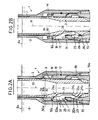
- FIGS. 2A and 2B are sectional views through an axial plane of symmetry and on a larger scale of the lower part of the lifting and handling grab.
- FIG. 2B shows the lower part of the lifting and handling device in the released position of the fuel assembly immersed in the liquid metal.
- the upper part of the lifting and handling grab is generally designated by the reference 1.
- the grapple 1 mainly comprises an external tubular body 2 and a slide 3 disposed inside the tubular body 2 and in its axial direction, with a certain radial clearance, the outside diameter of the slide 3 being substantially less than the inside diameter of the tubular body 2.
- the tubular body 2 is connected at its upper part to a housing 4 secured to the lower part of a lifting mast 5 of tubular shape which can be actuated to lift or lower the entire grapple vertically, by a device such as a winch not shown in FIG. 1 and connected to the upper part of the mast 5.
- the lifting mast 5 is associated with the fuel loading machine of the nuclear reactor in which the lifting grapple is used, the mast 5 passing through a rotating plug 6 rotatably mounted on the horizontal slab for closing the reactor vessel .
- the lifting device such as a winch connected to the upper part of the mast 5 and not shown in FIG. 1 is mounted, in this case, on the frame of the fuel loading machine. This device makes it possible to move the mast 5 and the entire lifting grab 1, in the vertical direction up or down (arrow 7).
- the reactor vessel contains liquid sodium 8 surmounted by a gaseous atmosphere 9 constituted by an inert gas such as argon.
- the housing 4 and the upper part of the tubular body 2 and of the slide 3 remain constantly immersed in the gaseous atmosphere 9.
- the lower part of the lifting grab 1 is introduced into the liquid sodium 8 in order to take up and handle the fuel assemblies in the reactor core submerged below the sodium level.
- the upper end part of the slide 3 disposed above the upper end of the tubular body 2 is engaged in the housing 4 and mounted sliding in the housing 4 by means of bearings 10.
- the upper part of the slide 3 is also connected in an articulated manner to two rods 11 pivotally mounted by means of an axis 12 on the casing 4.
- the end of the rods 11 opposite to the slide 3 is connected in an articulated manner to a rod actuator 13 arranged along the axis of the lifting mast 5. Any other mechanical system causing axial relative movement between the slide 3 and the tube 2 can be used.
- the upper end part of the actuating rod 13, not shown in FIG. 1, is accessible from the platform of the fuel loading machine to which the upper part of the mast 5 is connected, to allow the displacement of the rod 13 in the vertical direction up or down, so as to move the slider 3 in the vertical direction, as shown in the arrow 14.
- FIGS. 2A and 2B the lower part of the lifting and handling grab 1 is shown immersed in the liquid sodium 8 contained in the reactor vessel and in a position above the head 15 of a fuel assembly of the reactor core allowing this assembly to be taken up by the gripper gripping means.
- the lower part of the tubular body 2 of the grapple 1 diametrically widened constitutes a bell 16 open at its lower end 16a.
- three fingers 20 arranged at 120 ° from each other around the axis 19 of the tubular body 2 are mounted in the slots of the support 18 arranged at 120 ° from each other around the axis 19 of the tubular body 2 and bell 16.
- Each of the pivoting fingers 20 has a lower hooking portion 20a which is engaged, in the gripping position, as shown in FIG. 2A, in a groove 23 machined in the internal bore of the assembly head 15.
- the slide 3 is produced in tubular form and has in its lower part an area in which the wall of the tubular envelope of the slide is substantially greater than the thickness of the wall of the slide in its current part.
- cavities such as 24 are machined, at their upper part and at their lower part respectively, by ramps 24a and 24b inclined with respect to the axis 19, in one direction and in the other.
- Each of the fingers 20 comprises an upper actuating ramp 25a and a lower ramp 25b constituting the inner part of the attachment end 20a of the finger 20.
- the ramps 24b of the cavities 24 terminate towards the outside of the slide 3, by a support flange 24c substantially perpendicular to the axis 19 common to the tubular body 2 and to the slide 3.
- the downward movement of the slide 3 inside the tubular body 2 which can be controlled by the actuating rod 13 causes, when the fingers are in their gripping position as shown in FIG. 2A, bringing the ramps 24a and 25a into contact causing the tilting of the upper part of each of the fingers 20 towards the outside of the grapple, to reach the open position of the fingers, as shown in the figure 2B.
- the lower part 20a is then located in the cavity 24 outside the groove 23.
- the upward movement of the slide 3 stops when the support rim 24c of the slide comes to rest on the lower edge of the attachment portion 20a of the fingers 20.
- the grab 1 can then be lifted by means of the lifting mast 5 and of the housing 4 shown in FIG. 1.
- the attachment portion 20a of the fingers 20 comes to bear on the upper edge of the groove 23, so that during the lifting the weight of the assembly is supported by the slide 3 on which the assembly head 15 is supported by the hooking parts 20a of the fingers 20.
- the support of the assembly during lifting can also be provided, in a redundant manner, by the bell-shaped lower part 16 of the tubular body. 2, via the fingers 20 and their hinge pins 21.
- the devices according to the prior art do not allow the movement of an object such as a fuel assembly between a position immersed in a liquid metal and a position emerged in a gaseous atmosphere at a temperature below the temperature of solidification of the liquid metal, the pivoting fingers and their control mechanism being immersed in the liquid metal during the operation of taking the assembly.
- the pivoting fingers and the control mechanism are capable of retaining liquid metal, when the fuel assembly is raised above the level of the liquid metal, the fingers and the control mechanism then being in an atmosphere gas at a temperature below the solidification temperature of the liquid metal. The solidification of the liquid metal retained by the fingers and the control mechanism then risks preventing any possibility of opening the fingers.
- the lower part of the grapple is disposed inside the enlarged part 16 of the tubular casing 2 constituting a bell; the bell 16 is closed in leaktight manner at its upper part by an axially deformable element ensuring the junction between the slide and the internal surface of the bell 16.
- the deformable element 30 is constituted by a bellows comprising two coaxial envelopes 30a and 30b having successive waves in the axial direction.
- the corrugated walls of the bellows can be made, for example, of stainless steel.
- the bell 16 has, in its upper part, a part 16b projecting radially inwards relative to its internal surface, this projecting part 16b having the shape of a crown whose triangular section is visible in FIGS. 2A and 2B.
- the slider 3 comprises, on its external surface, a part 3b projecting radially outwards having the shape of a crown whose triangular section is visible in FIGS. 2A and 2B.
- the double-envelope bellows 30 is fixed by welding between the crowns 3b and 16b, the ends of the envelopes of the bellows 30 being tightly fixed by welding on the crowns 3b and 16b.
- the support 18 and the fingers 20 are fixed inside the bell 16, in the annular space 31, in an axial position intermediate between the bellows 30 and the lower open end 16a of the bell 16.
- the slide can be moved axially to actuate the fingers, as can be seen in FIGS. 2A and 2B.
- the bellows 30 is compressed as it can be seen in FIG. 2B.
- the bellows relaxes by elasticity, during the upward movement of the slide 3 realizing the closing of the fingers as shown in FIG. 2A.
- the slide 3 produced in tubular form can be used for blowing a cooling gas inside an assembly on which the grapple is engaged, during handling of the assembly above the level of the metal liquid.
- the grapple 1 is moved by means of the lifting mast 5 from a position situated above the level of the liquid metal to the position shown in FIG. 2B where the bell covers the head 15 of an assembly, the slide 3 being in its low position and the bellows 30 being compressed.
- the installation of the bell 16 on the assembly head 15 is facilitated by the fact that the bell 16 has a lower part with an enlarged diameter and that its lower opening 16a is chamfered inwards.
- inert gas such as argon fills the annular space 31 and the interior volume of the tubular slide 3.
- the gas contained in the internal volume of the slide 3 can escape inside the slide which is connected at its upper part to a device for blowing cooling gas.
- the gripping fingers 20 and their control means therefore remain constantly immersed in a gaseous atmosphere, during the positioning of the gripper on the assembly head 15 and during the operation of the fingers 20.
- the fingers 20 and their control mechanism are therefore not likely to come into contact with liquid metal which can freeze on the moving parts of the fingers.
- the assembly can therefore be moved thanks to the lifting grab 1, between its submerged position and a position emerged in the gaseous atmosphere located above the level of the liquid metal, without this operation being accompanied by a freezing of metal. liquid on the moving parts of the grapple.
- the assembly can therefore be moved and handled, from its submerged position, using only the lifting grab 1 which can operate successively in the liquid metal and in the gaseous atmosphere surmounting the liquid metal.
- the level of the liquid metal inside the slide remains identical to the upper level 8a of the liquid metal in the reactor vessel.
- the lifting grab according to the invention therefore makes it possible to carry out, in a simple and rapid manner, handling operations consisting in moving fuel assemblies from a position immersed in a liquid metal to an emerged position in which the fuel assembly is immersed in a gaseous atmosphere surmounting the liquid metal.
- the deformable elastic member can be constituted in a different form from a double-envelope bellows, as described above.
- the fingers of the grapple and their control means can be produced in a form different from that which has been described.
- the slide can be associated with an orientation lock variable, articulated on this slide and whose orientation is modified in the lower position of the slide by a fixed finger secured to the tubular body, the given orientation bringing the lock, according to its previous orientation, either to a relaxed position or to a locked position .
- the grapple lifting cable is connected to the slide on which the tubular body rests. When the tubular body comes to bear on the object which is being handled, the slide can move in the tubular body to its low position, by gravity. In this case, the entire grapple only has a lifting cable ensuring the operation of the slide and the transport of the tubular body and the load.
- the grapple according to the invention can be used to carry out any handling operation of any object such as a mechanical part to ensure its movement between a position immersed in a liquid metal or other hot liquid and an emerged position where the object is at least partially immersed in a gaseous atmosphere.
- the grapple according to the invention can be used, outside the field of nuclear reactors cooled by liquid metal and for example in applications using a bath of molten salts.
- lifting grab can be associated with handling means making it possible to move the object not only in the vertical direction but also in one or more horizontal directions.
Landscapes
- Physics & Mathematics (AREA)
- Engineering & Computer Science (AREA)
- Plasma & Fusion (AREA)
- General Engineering & Computer Science (AREA)
- High Energy & Nuclear Physics (AREA)
- Load-Engaging Elements For Cranes (AREA)
- Manipulator (AREA)
Applications Claiming Priority (2)
| Application Number | Priority Date | Filing Date | Title |
|---|---|---|---|
| FR9002046 | 1990-02-20 | ||
| FR9002046A FR2658654B1 (fr) | 1990-02-20 | 1990-02-20 | Grappin de levage et de deplacement d'un objet entre une position immergee dans un liquide chaud tel qu'un metal et une position emergee dans un gaz. |
Publications (1)
| Publication Number | Publication Date |
|---|---|
| EP0443904A1 true EP0443904A1 (de) | 1991-08-28 |
Family
ID=9393921
Family Applications (1)
| Application Number | Title | Priority Date | Filing Date |
|---|---|---|---|
| EP91400327A Withdrawn EP0443904A1 (de) | 1990-02-20 | 1991-02-11 | Greifer für das Heben und die Handhabung eines Gegenstandes zwischen eine in einer heissen Flüssigkeit -z.B. einem Metall- getauchte Stellung und eine in einem Gas aufgetauchte Stellung |
Country Status (5)
| Country | Link |
|---|---|
| US (1) | US5128095A (de) |
| EP (1) | EP0443904A1 (de) |
| JP (1) | JP2945767B2 (de) |
| FR (1) | FR2658654B1 (de) |
| RU (1) | RU1838837C (de) |
Families Citing this family (3)
| Publication number | Priority date | Publication date | Assignee | Title |
|---|---|---|---|---|
| US6327322B1 (en) * | 1999-07-27 | 2001-12-04 | Westinghouse Electric Company Llc | Interlock assembly for burnable poison rod transfer device |
| CN108818590B (zh) * | 2018-07-23 | 2022-12-30 | 中国地质大学(武汉) | 液态金属型机器人灵巧手 |
| CN117620960A (zh) * | 2023-12-22 | 2024-03-01 | 中乌先楚核能科技有限公司 | 一种水下辐照监督设备的拆装工具 |
Citations (4)
| Publication number | Priority date | Publication date | Assignee | Title |
|---|---|---|---|---|
| FR1157964A (fr) * | 1956-09-11 | 1958-06-05 | Commissariat Energie Atomique | Nouveau dispositif de chargement et déchargement des barres actives d'une pile atomique |
| GB1009333A (en) * | 1961-02-17 | 1965-11-10 | Atomic Energy Authority Uk | Improvements relating to handling equipment for radioactive charges |
| FR2410866A1 (fr) * | 1977-11-30 | 1979-06-29 | Savin Nikolai | Reacteur nucleaire |
| FR2582438A1 (fr) * | 1985-05-21 | 1986-11-28 | Commissariat Energie Atomique | Hotte de manutention et de transport d'assemblages de combustible nucleaire et installation comportant une hotte de ce type |
Family Cites Families (4)
| Publication number | Priority date | Publication date | Assignee | Title |
|---|---|---|---|---|
| US3883012A (en) * | 1971-10-21 | 1975-05-13 | Transfer Systems | Dry cask handling system for shipping nuclear fuel |
| US4259153A (en) * | 1977-05-25 | 1981-03-31 | Pryamilov Jury S | Device for removal of fuel assemblies and cans of control and safety system from core of nuclear reactor |
| FR2431907A1 (fr) * | 1978-07-28 | 1980-02-22 | Novatome Ind | Grappin automatique |
| US4713210A (en) * | 1985-11-18 | 1987-12-15 | General Electric Company | Control rod driveline and grapple |
-
1990
- 1990-02-20 FR FR9002046A patent/FR2658654B1/fr not_active Expired - Fee Related
-
1991
- 1991-02-11 EP EP91400327A patent/EP0443904A1/de not_active Withdrawn
- 1991-02-19 RU SU914894433A patent/RU1838837C/ru active
- 1991-02-19 JP JP3024740A patent/JP2945767B2/ja not_active Expired - Fee Related
- 1991-02-20 US US07/658,323 patent/US5128095A/en not_active Expired - Fee Related
Patent Citations (4)
| Publication number | Priority date | Publication date | Assignee | Title |
|---|---|---|---|---|
| FR1157964A (fr) * | 1956-09-11 | 1958-06-05 | Commissariat Energie Atomique | Nouveau dispositif de chargement et déchargement des barres actives d'une pile atomique |
| GB1009333A (en) * | 1961-02-17 | 1965-11-10 | Atomic Energy Authority Uk | Improvements relating to handling equipment for radioactive charges |
| FR2410866A1 (fr) * | 1977-11-30 | 1979-06-29 | Savin Nikolai | Reacteur nucleaire |
| FR2582438A1 (fr) * | 1985-05-21 | 1986-11-28 | Commissariat Energie Atomique | Hotte de manutention et de transport d'assemblages de combustible nucleaire et installation comportant une hotte de ce type |
Also Published As
| Publication number | Publication date |
|---|---|
| FR2658654A1 (fr) | 1991-08-23 |
| FR2658654B1 (fr) | 1994-01-07 |
| JPH0527085A (ja) | 1993-02-05 |
| US5128095A (en) | 1992-07-07 |
| JP2945767B2 (ja) | 1999-09-06 |
| RU1838837C (ru) | 1993-08-30 |
Similar Documents
| Publication | Publication Date | Title |
|---|---|---|
| EP2609029B1 (de) | Vorrichtung zur handhabung von trommeln, gerät zur übertragung von pulverstoffen und übertragungsverfahren | |
| EP2617040B1 (de) | Vorrichtung zur trockenhandhabung von kernbrennstabbündeln | |
| EP2741298B1 (de) | System zum Greifen und Verriegeln / Entriegeln | |
| WO2004066312A1 (fr) | Procede d’elaboration d'un conteneur ferme, ledit conteneur ferme et ses elements constitutifs | |
| EP0443904A1 (de) | Greifer für das Heben und die Handhabung eines Gegenstandes zwischen eine in einer heissen Flüssigkeit -z.B. einem Metall- getauchte Stellung und eine in einem Gas aufgetauchte Stellung | |
| EP2092533B1 (de) | Kernbrennstoff-transporteinrichtung und verfahren zum beladen/entladen der einrichtung | |
| EP2656352B1 (de) | Einrichtung zur langzeitlagerung mit einem belüfteten lagerkanister zum umschliessen eines radioaktive materialien enthaltenden sicherheitskanisters | |
| FR2530366A1 (fr) | Procede pour le confinement etanche au gaz d'elements radioactifs et installation pour la mise en oeuvre dudit procede | |
| EP0238767B1 (de) | Zusammenbau eines abnehmbaren und verriegelbaren Führungsringes mit einem Platte und seine Anwendung für ein Führungsrohr eines Kernreaktors | |
| EP0348250A1 (de) | Vorrichtung zum Öffnen und Schliessen eines Filters in einer Kernanlage und Verfahren zum Auswechseln in einer Filtergarnitur | |
| EP2789550B1 (de) | Handhabungs- und Begrenzungshaube, Anwendung zur Handhabung von Probengefäßen für nukleares Material, insbesondere Kernbrennstoffe | |
| FR2582438A1 (fr) | Hotte de manutention et de transport d'assemblages de combustible nucleaire et installation comportant une hotte de ce type | |
| EP0051241B1 (de) | Verfahren und Vorrichtung zum Handhaben langgestreckter grosser Gegenstände | |
| EP0562913B1 (de) | Gefäss mit mehreren getrennten Betten von Feststoffen mit Schwerkraftentleerung ohne mischen des Materials | |
| EP0463913A1 (de) | Automatische Fördervorrichtung für mehrere Positionier- oder Verbindungselemente | |
| EP0011005B1 (de) | Probenahmekopf für Kühlmittel eines Kernreaktors | |
| EP0463921A1 (de) | Vorrichtung zum Öffnen und zum dichten Verschluss einer Durchführung zwischen dem Hohlraum eines transportierbaren Behälters und einem feststehenden senkrechten Schacht | |
| EP0218485B1 (de) | Handhabungseinrichtung zum Einführen und Herausziehen einer Apparatur durch eine Öffnung in einem dichten Gehäuse | |
| FR2486295A1 (fr) | Coeur de reacteur nucleaire d'axe vertical, notamment pour reacteur du type refroidi par un metal liquide | |
| FR2576291A1 (fr) | Corbeille a papiers a verrouillage automatique | |
| FR2676140A1 (fr) | Dispositif d'insertion d'une capsule d'irradiation dans un panier solidaire des equipements internes d'un reacteur nucleaire. | |
| EP0363266A1 (de) | Kernbrennelement-Transferbaum und solchen Transferbaum aufweisender Kernreaktor | |
| EP3084772B1 (de) | Vorrichtung zur zusammenfügung mit einem behälter mit bestrahltem brennstoff unter einer kernkraftanlagengrube und mit bestrahltem brennstoff | |
| FR2584154A1 (fr) | Crochet a prise et depose automatique fonctionnant par gravite | |
| EP0150148A2 (de) | Kernreaktor mit schnellen Neutronen, der mit einem zentralen Wartungsraum und einem aus Maschinenräumen bestehenden Verschlussteil versehen ist |
Legal Events
| Date | Code | Title | Description |
|---|---|---|---|
| PUAI | Public reference made under article 153(3) epc to a published international application that has entered the european phase |
Free format text: ORIGINAL CODE: 0009012 |
|
| AK | Designated contracting states |
Kind code of ref document: A1 Designated state(s): BE DE GB IT |
|
| 17P | Request for examination filed |
Effective date: 19910807 |
|
| 17Q | First examination report despatched |
Effective date: 19940414 |
|
| STAA | Information on the status of an ep patent application or granted ep patent |
Free format text: STATUS: THE APPLICATION HAS BEEN WITHDRAWN |
|
| 18W | Application withdrawn |
Withdrawal date: 19940824 |