EP0443901A1 - Rotorcraft main gearbox having an emergency lubrication device - Google Patents
Rotorcraft main gearbox having an emergency lubrication device Download PDFInfo
- Publication number
- EP0443901A1 EP0443901A1 EP91400321A EP91400321A EP0443901A1 EP 0443901 A1 EP0443901 A1 EP 0443901A1 EP 91400321 A EP91400321 A EP 91400321A EP 91400321 A EP91400321 A EP 91400321A EP 0443901 A1 EP0443901 A1 EP 0443901A1
- Authority
- EP
- European Patent Office
- Prior art keywords
- emergency
- lubrication
- circuit
- oil
- normal
- Prior art date
- Legal status (The legal status is an assumption and is not a legal conclusion. Google has not performed a legal analysis and makes no representation as to the accuracy of the status listed.)
- Granted
Links
Images

Classifications
-
- F—MECHANICAL ENGINEERING; LIGHTING; HEATING; WEAPONS; BLASTING
- F16—ENGINEERING ELEMENTS AND UNITS; GENERAL MEASURES FOR PRODUCING AND MAINTAINING EFFECTIVE FUNCTIONING OF MACHINES OR INSTALLATIONS; THERMAL INSULATION IN GENERAL
- F16N—LUBRICATING
- F16N29/00—Special means in lubricating arrangements or systems providing for the indication or detection of undesired conditions; Use of devices responsive to conditions in lubricating arrangements or systems
- F16N29/02—Special means in lubricating arrangements or systems providing for the indication or detection of undesired conditions; Use of devices responsive to conditions in lubricating arrangements or systems for influencing the supply of lubricant
-
- B—PERFORMING OPERATIONS; TRANSPORTING
- B64—AIRCRAFT; AVIATION; COSMONAUTICS
- B64C—AEROPLANES; HELICOPTERS
- B64C27/00—Rotorcraft; Rotors peculiar thereto
- B64C27/04—Helicopters
- B64C27/12—Rotor drives
-
- F—MECHANICAL ENGINEERING; LIGHTING; HEATING; WEAPONS; BLASTING
- F16—ENGINEERING ELEMENTS AND UNITS; GENERAL MEASURES FOR PRODUCING AND MAINTAINING EFFECTIVE FUNCTIONING OF MACHINES OR INSTALLATIONS; THERMAL INSULATION IN GENERAL
- F16H—GEARING
- F16H57/00—General details of gearing
- F16H57/04—Features relating to lubrication or cooling or heating
- F16H57/0402—Cleaning of lubricants, e.g. filters or magnets
- F16H57/0404—Lubricant filters
-
- F—MECHANICAL ENGINEERING; LIGHTING; HEATING; WEAPONS; BLASTING
- F16—ENGINEERING ELEMENTS AND UNITS; GENERAL MEASURES FOR PRODUCING AND MAINTAINING EFFECTIVE FUNCTIONING OF MACHINES OR INSTALLATIONS; THERMAL INSULATION IN GENERAL
- F16H—GEARING
- F16H57/00—General details of gearing
- F16H57/04—Features relating to lubrication or cooling or heating
- F16H57/0434—Features relating to lubrication or cooling or heating relating to lubrication supply, e.g. pumps ; Pressure control
- F16H57/0442—Features relating to lubrication or cooling or heating relating to lubrication supply, e.g. pumps ; Pressure control for supply in case of failure, i.e. auxiliary supply
-
- F—MECHANICAL ENGINEERING; LIGHTING; HEATING; WEAPONS; BLASTING
- F16—ENGINEERING ELEMENTS AND UNITS; GENERAL MEASURES FOR PRODUCING AND MAINTAINING EFFECTIVE FUNCTIONING OF MACHINES OR INSTALLATIONS; THERMAL INSULATION IN GENERAL
- F16H—GEARING
- F16H57/00—General details of gearing
- F16H57/04—Features relating to lubrication or cooling or heating
- F16H57/045—Lubricant storage reservoirs, e.g. reservoirs in addition to a gear sump for collecting lubricant in the upper part of a gear case
-
- F—MECHANICAL ENGINEERING; LIGHTING; HEATING; WEAPONS; BLASTING
- F16—ENGINEERING ELEMENTS AND UNITS; GENERAL MEASURES FOR PRODUCING AND MAINTAINING EFFECTIVE FUNCTIONING OF MACHINES OR INSTALLATIONS; THERMAL INSULATION IN GENERAL
- F16H—GEARING
- F16H57/00—General details of gearing
- F16H57/04—Features relating to lubrication or cooling or heating
- F16H57/0456—Lubrication by injection; Injection nozzles or tubes therefor
-
- F—MECHANICAL ENGINEERING; LIGHTING; HEATING; WEAPONS; BLASTING
- F16—ENGINEERING ELEMENTS AND UNITS; GENERAL MEASURES FOR PRODUCING AND MAINTAINING EFFECTIVE FUNCTIONING OF MACHINES OR INSTALLATIONS; THERMAL INSULATION IN GENERAL
- F16H—GEARING
- F16H57/00—General details of gearing
- F16H57/04—Features relating to lubrication or cooling or heating
- F16H57/0467—Elements of gearings to be lubricated, cooled or heated
- F16H57/0469—Bearings or seals
- F16H57/0471—Bearing
Abstract
Description
L'invention a pour objet un dispositif de lubrification de secours destiné à prolonger le temps de fonctionnement, et améliorer la sécurité d'un réducteur à engrenages dans le cas où la lubrification normale est hors service, et concerne plus particulièrement un dispositif pour assurer une lubrification minimale des organes essentiels du réducteur. Elle s'applique plus particulièrement aux boîtes de transmission principales interposées entre le ou les moteurs et le ou les rotors de giravions.The subject of the invention is an emergency lubrication device intended to extend the operating time and improve the safety of a gear reducer in the case where the normal lubrication is out of service, and more particularly relates to a device for ensuring a minimum lubrication of essential gear units. It applies more particularly to the main gearboxes interposed between the engine or engines and the rotors of rotorcraft.
Dans ces boîtes de transmission, les organes de réduction, engrenages et roulements, sont généralement lubrifiés par de l'huile sous pression grâce à une ou à des pompes de lubrification qui sont entraînées par des jeux d'engrenages prenant leur mouvement sur une chaîne principale du réducteur, ou par une source d'entraînement annexe.In these gearboxes, the reduction members, gears and bearings, are generally lubricated by pressurized oil thanks to one or more lubrication pumps which are driven by sets of gears taking their movement on a main chain. of the reducer, or by an additional drive source.
Il est évidemment important, lorsque le système normal de lubrification du réducteur principal est défaillant, soit par épuisement de fluide dû à une fuite, soit par la détérioration du générateur de pression ou de la pompe, qu'un système de lubrification minimale puisse s'y substituer. Ainsi un giravion pourraît, en cas de besoin, rejoindre au minimum de puissance, un point d'atterrissage favorable. Ceci serait particulièrement avantageux pour les giravions amenés à faire des survols maritimes prolongés, par exemple ceux utilisés au profit de l'exploitation pétrolière "offshore".It is obviously important, when the normal lubrication system of the main reducer is faulty, either by exhaustion of fluid due to a leak, or by the deterioration of the pressure generator or the pump, that a minimal lubrication system can be replace it. Thus a rotorcraft could, if necessary, reach at least power, a favorable landing point. This would be particularly advantageous for rotorcraft having to make prolonged maritime overflights, for example those used for the benefit of "offshore" oil exploitation.
Il existe déjà des systèmes de lubrification de sécurité adaptés à des véhicules ou des bateaux, qui consistent à prévoir au moins un réservoir auxiliaire d'huile, disposé en un point plus élevé que les mécanismes à lubrifier. Par exemple dans le US-A 4721185 est décrit un système à réserve d'huile pour véhicules dans lequel un réservoir complémentaire alimenté en huile, sert à fournir de l'huile filtrée, aspirée par une pompe, au système hydraulique du véhicule. Il y a donc, pour extraire l'huile du réservoir, une pompe qui n'est pas à l'abri d'une anomalie de fonctionnement. Dans un autre domaine tel que celui des bateaux, comme montré par exemple dans le US-A 2988 154, un circuit normal de lubrification est apte à alimenter un second réservoir en situation élevée, avec des pompes et vannes permettant de maintenir une pression d'huile égale quelles que soient les conditions d'utilisation.There are already safety lubrication systems suitable for vehicles or boats, which consist in providing at least one auxiliary oil tank, arranged at a point higher than the mechanisms to be lubricated. For example, in US-A 4721185, an oil reserve system for vehicles is described in which an additional oil-supplied tank is used to supply filtered oil, sucked by a pump, to the hydraulic system of the vehicle. So there is, to extract the oil of the tank, a pump which is not immune to an operating anomaly. In another field such as that of boats, as shown for example in US-A 2988 154, a normal lubrication circuit is capable of supplying a second tank in high conditions, with pumps and valves making it possible to maintain a pressure of oil equal whatever the conditions of use.
Tous ces systèmes sont des systèmes de lubrification de sécurité destinés à pallier une défaillance partielle ou totale de la génération de la pression et utilisent le circuit de distribution du dispositif normal pour assurer une lubrification équivalente. Mais un tel système de secours reste inopérant si le circuit normal est lui-même totalement défaillant, par exemple à la suite de la perte totale du fluide de lubrification. C'est pourquoi la Demanderesse a imaginé un dispositif qui assure une lubrification minimale des organes essentiels du réducteur, même s'il y a absence accidentelle d'alimentation du circuit normal et du circuit auxiliaire de sécurité, pour la lubrification sous pression dudit réducteur, y compris lorsque la réserve normale d'huile dans laquelle puise le circuit normal de lubrification est épuisée. Le dispositif en question permet donc un minimum de lubrification pour assurer le fonctionnement du réducteur pendant un temps suffisant pour permettre un atterrissage dans de bonnes conditions de sécurité.All these systems are safety lubrication systems intended to compensate for a partial or total failure in the generation of pressure and use the distribution circuit of the normal device to ensure equivalent lubrication. However, such an emergency system remains inoperative if the normal circuit is itself totally faulty, for example following the total loss of the lubrication fluid. This is why the Applicant has imagined a device which ensures minimum lubrication of the essential organs of the reducer, even if there is an accidental absence of supply to the normal circuit and the auxiliary safety circuit, for the lubrication under pressure of said reducer, including when the normal oil reserve from which the normal lubrication circuit draws is depleted. The device in question therefore allows a minimum of lubrication to ensure the operation of the reduction gear for a sufficient time to allow a landing in good safety conditions.
L'invention a donc pour objet un dispositif de lubrification de secours pour réducteur et plus particulièrement pour une boîte de transmission principale de giravion dans lequel un circuit normal de lubrification alimenté par une pompe puisant dans un réservoir inférieur normal distribue l'huile sous pression, par des gicleurs, en direction du réducteur, dispositif selon lequel au moins un conduit de dérivation provenant du circuit normal alimente en huile au moins un réservoir de secours placé à la partie supérieure du réducteur, ledit réservoir distribuant l'huile en continu par gravité sur les éléments critiques du réducteur.The subject of the invention is therefore a backup lubrication device for a reduction gear and more particularly for a main rotorcraft gearbox in which a normal lubrication circuit supplied by a pump drawing from a normal lower reservoir distributes the oil under pressure, by jets, in the direction of the reducer, device according to which at least one bypass duct coming from the normal circuit supplies oil with at least one emergency reservoir placed at the top of the reducer, said reservoir distributing the oil continuously by gravity on the critical elements of the gearbox.
Selon des caractéristiques particulières de l'invention, la partie supérieure du réservoir de secours est ouverte pour former déversoir pour l'huile et autoriser son retour vers le réservoir inférieur. En outre, le réservoir de secours est pourvu, à sa partie inférieure, de conduits d'alimentation de secours pour lubrifier par gravité les éléments critiques du réducteur. Ce circuit de distribution de secours comporte une limitation de débit de telle sorte que la quantité d'huile distribuée par ce circuit soit minimale mais cependant suffisante pour éviter toute détérioration grave des éléments critiques du réducteur pendant la durée souhaitée pour son fonctionnement en secours, le circuit normal de distribution étant totalement inopérant.According to particular features of the invention, the upper part of the emergency tank is open to form a weir for the oil and allow its return to the lower tank. In addition, the emergency tank is provided, at its lower part, with emergency supply lines to lubricate by gravity the critical elements of the reducer. This emergency distribution circuit includes a flow limitation so that the quantity of oil distributed by this circuit is minimal but nevertheless sufficient to avoid any serious deterioration of the critical elements of the reducer during the period desired for its emergency operation, the normal distribution circuit being totally inoperative.
En variante une pompe de secours est prévue sur au moins un conduit d'alimentation de secours pour alimenter des gicleurs de secours à faible débit.As a variant, an emergency pump is provided on at least one emergency supply duct for supplying emergency nozzles with low flow rate.
D'autres caractéristiques et avantages de l'invention apparaîtront à la lecture de la description qui va suivre de formes de réalisation faisant référence aux dessins annexés qui représentent :
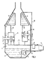
- figure 1 une vue schématique en coupe d'un dispositif de lubrification en fonctionnement normal ;
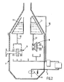
- figure 2 la même vue en fonctionnement de secours ;
- figure 3 une variante de réalisation en fonctionnement de secours.
- Figure 1 a schematic sectional view of a lubrication device in normal operation;
- Figure 2 the same view in emergency operation;
- Figure 3 an alternative embodiment in emergency operation.
On a représenté schématiquement à la figure 1 une boîte 1 de transmission principale d'un giravion disposant à sa partie inférieure d'un réservoir d'huile 2. Le circuit normal de lubrification 3 alimenté par une pompe 4, traverse un échangeur 5 et un filtre 6 et distribue l'huile sous pression par des gicleurs d'alimentation 7, en direction des organes réducteurs 8 et 9 constitués d'engrenages portés par des arbres tournant sur des roulements. Un conduit de dérivation 10 provenant du circuit normal 3 distribue de l'huile filtrée vers un réservoir de secours 11, placé à la partie supérieure de la boîte 1, dont la partie supérieure ouverte forme déversoir et autorise le débordement de l'huile et son retour vers le réservoir normal inférieur 2. Le réservoir de secours est pourvu, à sa partie inférieure, de conduits d'alimentation de secours calibrés 12 qui permettent de lubrifier par gravité et par le dessus, les éléments critiques des réducteurs 8 et 9. Cet apport complémentaire d'huile par les conduits de secours peut doubler l'arrivée normale par les gicleurs 7, ou encore constituer l'unique système d'alimentation locale en huile.There is shown diagrammatically in FIG. 1 a
En fonctionnement normal, c'est-à-dire lorsque le circuit normal de lubrification 3, est alimenté par le réservoir 2, le débit d'huile acheminé par le conduit 10 vers le réservoir de secours 11 est supérieur au débit d'huile s'écoulant par gravité dans les conduits de secours calibrés 12 en direction des réducteurs. Il en résulte que le réservoir de secours 11 est toujours rempli et déborde par son déversoir ce qui assure le retour du trop-plein d'huile vers le réservoir normal inférieur 2.In normal operation, that is to say when the normal lubrication circuit 3, is supplied by the tank 2, the oil flow conveyed by the
S'il y a une perte d'huile au fond de ce réservoir 2 ou une panne du système de lubrification normal (fuite dans le circuit, panne de la pompe 4, colmatage du filtre 6 etc...), comme on le voit à la figure 2, le réservoir de secours 11 va se vider progressivement en continuant de lubrifier par les conduits 12, les éléments critiques des réducteurs. Le réservoir de secours est dimensionné de telle sorte qu'il permet de disposer en permanence d'une réserve d'huile disponible pour alimenter à faible débit les éléments critiques du réducteur, ce faible débit étant obtenu par un dimensionnement approprié des conduits de secours 12 et la présence de gicleurs pour contrôler ce débit. On peut ainsi, puisque le réservoir de secours 11 a une charge de contenance significative et qu'il y a un faible débit de vidange dans le circuit de secours, assurer une lubrification minimale des éléments critiques de la boîte pendant un temps de fonctionnement suffisant pour rejoindre un terrain d'atterrissage adéquat.Ce circuit de distribution de la lubrification de secours est spécialement aménagé et indépendant du circuit normal sous pression de façon à optimiser la répartition du lubrifiant contenu dans le réservoir de secours, aux organes critiques, tant du point de vue du nombre de points à lubrifier et de leur choix, qu'à celui de la quantité de lubrifiant devant être acheminée à chaque point à lubrifier. Pour cela le circuit de distribution est calibré de façon très précise.If there is a loss of oil at the bottom of this tank 2 or a failure of the normal lubrication system (leak in the circuit, failure of the pump 4, clogging of the filter 6 etc ...), as we see in FIG. 2, the
Dans la variante illustrée à la figure 3 est prévue une pompe de secours 13 sur au moins un conduit d'alimentation de secours 12, qui alimente des gicleurs de secours 14 à faible débit. La pompe 13 est entraînée par la boîte de transmission principale et possède une alarme 15 de basse pression d'huile. Celle-ci permet de surveiller en permanence le bon fonctionnement de ce circuit et dans le cas d'un fonctionnement de secours, d'indiquer au pilote l'épuisement de la réserve d'huile de secours.In the variant illustrated in FIG. 3, an
Claims (5)
Applications Claiming Priority (2)
| Application Number | Priority Date | Filing Date | Title |
|---|---|---|---|
| FR9002015 | 1990-02-20 | ||
| FR9002015A FR2658577A1 (en) | 1990-02-20 | 1990-02-20 | EMERGENCY LUBRICATION DEVICE FOR REDUCER, PARTICULARLY FOR A MAIN TRANSMISSION OF A GIRAVION. |
Publications (2)
| Publication Number | Publication Date |
|---|---|
| EP0443901A1 true EP0443901A1 (en) | 1991-08-28 |
| EP0443901B1 EP0443901B1 (en) | 1995-04-19 |
Family
ID=9393904
Family Applications (1)
| Application Number | Title | Priority Date | Filing Date |
|---|---|---|---|
| EP91400321A Expired - Lifetime EP0443901B1 (en) | 1990-02-20 | 1991-02-11 | Rotorcraft main gearbox having an emergency lubrication device |
Country Status (4)
| Country | Link |
|---|---|
| US (1) | US5121815A (en) |
| EP (1) | EP0443901B1 (en) |
| DE (1) | DE69108960T2 (en) |
| FR (1) | FR2658577A1 (en) |
Cited By (8)
| Publication number | Priority date | Publication date | Assignee | Title |
|---|---|---|---|---|
| FR2685758A1 (en) * | 1991-12-26 | 1993-07-02 | Aerospatiale | System for emergency lubrication and cooling of a mechanical stepup/stepdown gearing of the "transmission box" type for a helicopter in the event of failure of the lubrication circuit |
| EP0696697A1 (en) * | 1994-08-12 | 1996-02-14 | Toyota Jidosha Kabushiki Kaisha | Device for effective lubrication of vehicle power transmission system upon starting of vehicle |
| US5643127A (en) * | 1995-03-06 | 1997-07-01 | Toyota Jidosha Kabushiki Kaisha | Vehicle power transmission having fluid-tight enclosure accommodating lubricating points and storing lubricating oil delivered from mechanical oil pump |
| WO2011059450A1 (en) | 2009-11-16 | 2011-05-19 | Bell Helicopter Textron Inc. | Emergency subsystem for a fluid system |
| WO2013007543A1 (en) * | 2011-07-08 | 2013-01-17 | Robert Bosch Gmbh | Lubrication system, internal combustion engine, and method for operating a lubrication system |
| FR3027998A1 (en) * | 2014-10-31 | 2016-05-06 | Airbus Helicopters | DUAL CIRCUIT RELIABLE LUBRICATION METHOD AND DEVICE OF A MAIN POWER TRANSMISSION BOX OF AN AIRCRAFT |
| EP3104044A1 (en) | 2015-06-11 | 2016-12-14 | Airbus Helicopters | A power transmission gearbox and an aircraft |
| US11834165B2 (en) | 2020-10-13 | 2023-12-05 | Airbus Helicopters | Method for improving the aerodynamic behavior of rotorcraft blades during hovering flight by moving the leading edge of the aerodynamic profiles of these blades |
Families Citing this family (59)
| Publication number | Priority date | Publication date | Assignee | Title |
|---|---|---|---|---|
| JPH0483955A (en) * | 1990-07-21 | 1992-03-17 | Nissan Motor Co Ltd | Working pressure circuit for automatic transmission |
| US5189929A (en) * | 1992-03-09 | 1993-03-02 | United Technologies Corporation | System and method for transmission gearbox noise control utilizing localized oil cooling/heating |
| US6131834A (en) * | 1999-03-08 | 2000-10-17 | Teeter; Monty J. | Self-propelled irrigation system |
| DE10051356B4 (en) * | 2000-10-17 | 2004-05-06 | Daimlerchrysler Ag | Transmission for a reciprocating internal combustion engine |
| FR2831938B1 (en) * | 2001-11-07 | 2004-02-20 | Eurocopter France | LUBRICATION SYSTEM FOR TILTING POWER TRANSMISSION BOX |
| DE10206019A1 (en) * | 2002-02-14 | 2003-08-28 | Zahnradfabrik Friedrichshafen | Gearbox especially for vehicle drive, has transport machine that delivers pressure medium to reservoir container arranged above gearbox |
| US7174997B2 (en) * | 2003-07-03 | 2007-02-13 | United Technologies Corporation | Failure tolerant passive lubrication system |
| US7387189B2 (en) * | 2003-08-14 | 2008-06-17 | United Technologies Corp. | Emergency lubrication system |
| US20060231337A1 (en) * | 2005-04-11 | 2006-10-19 | The Falk Corporation | Elevated oil reservoir collection and distribution system |
| JP2006301289A (en) * | 2005-04-20 | 2006-11-02 | Tokyo Ohka Kogyo Co Ltd | Negative resist composition and resist pattern forming method |
| DE602005005658T2 (en) * | 2005-06-30 | 2009-06-18 | Agusta S.P.A. | Helicopter with auxiliary lubricating oil circuit |
| EP1739011B1 (en) * | 2005-06-30 | 2008-05-14 | Agusta S.p.A. | Improved helicopter transmission |
| US8602166B2 (en) * | 2006-01-05 | 2013-12-10 | Sikorsky Aircraft Corporation | Secondary lubrication system with injectable additive |
| US7789200B2 (en) | 2006-11-14 | 2010-09-07 | Rolls-Royce Corporation | Sump housing |
| US7878303B2 (en) * | 2006-11-14 | 2011-02-01 | Rolls-Royce Corporation | Lubrication scavenge system |
| US8020665B2 (en) | 2006-11-22 | 2011-09-20 | United Technologies Corporation | Lubrication system with extended emergency operability |
| US8215454B2 (en) * | 2006-11-22 | 2012-07-10 | United Technologies Corporation | Lubrication system with tolerance for reduced gravity |
| US20090129956A1 (en) * | 2007-11-21 | 2009-05-21 | Jean-Louis Picouet | Compressor System and Method of Lubricating the Compressor System |
| GB2466426B (en) * | 2008-12-05 | 2014-02-05 | Gm Global Tech Operations Inc | Lubrication device |
| EP2501483B1 (en) * | 2009-11-16 | 2015-08-19 | Bell Helicopter Textron Inc. | Dual-path fluid injection jet |
| US9086055B2 (en) * | 2010-01-11 | 2015-07-21 | General Electric Company | Lubrication of fluid turbine gearbox during idling or loss of electric grid |
| US20110168494A1 (en) * | 2010-01-11 | 2011-07-14 | General Electric Company | Lubrication of wind turbine gearbox during idling or loss of electric grid |
| DE102010033228A1 (en) * | 2010-08-03 | 2012-02-09 | Siemens Aktiengesellschaft | Device for spray lubrication of a wind turbine gearbox |
| GB201113821D0 (en) * | 2010-12-13 | 2011-09-28 | Agco Corp | Common power lubricated gearboxes on combine harvester |
| US9458923B2 (en) * | 2011-03-31 | 2016-10-04 | Textron Innovations Inc. | Gearbox with passive lubrication system |
| US8944216B2 (en) * | 2011-04-14 | 2015-02-03 | United Technologies Corporation | Lubricating transfer tube |
| JP5816071B2 (en) * | 2011-12-13 | 2015-11-17 | コベルコ建機株式会社 | Construction machine drive |
| US8651240B1 (en) | 2012-12-24 | 2014-02-18 | United Technologies Corporation | Pressurized reserve lubrication system for a gas turbine engine |
| US8985278B2 (en) | 2012-09-07 | 2015-03-24 | United Technologies Corporation | Lubrication system having segmented anti-backflow feature |
| DE102013224017A1 (en) | 2013-11-25 | 2015-05-28 | Zf Friedrichshafen Ag | Emergency lubrication for wind turbine gearbox |
| FR3027992B1 (en) * | 2014-10-31 | 2016-12-09 | Airbus Helicopters | LUBRICATION DEVICE WITH INCREASED TRIPLE CIRCUIT RELIABILITY OF A MAIN POWER TRANSMISSION BOX OF AN AIRCRAFT |
| DE102014016173A1 (en) * | 2014-11-03 | 2016-05-04 | Audi Ag | Drive device for a motor vehicle |
| WO2016171786A1 (en) * | 2015-04-21 | 2016-10-27 | Sikorsky Aircraft Corporation | Gearbox lubrication system for aircraft |
| US9683652B2 (en) * | 2015-04-22 | 2017-06-20 | Bell Helicopter Textron Inc. | Method for the delivery of lubricant to a rotorcraft gearbox |
| US9909453B2 (en) | 2015-05-19 | 2018-03-06 | General Electric Company | Lubrication system for a turbine engine |
| US10458517B2 (en) * | 2015-05-22 | 2019-10-29 | Dana Heavy Vehicle Systems Group, Llc | Internal lube tank lube level control system |
| US20170138461A1 (en) | 2015-08-12 | 2017-05-18 | Sikorsky Aircraft Corporation | Lubrication systems |
| US10415429B2 (en) | 2015-09-25 | 2019-09-17 | General Electric Company | Planet gearbox with cylindrical roller bearing with high density roller packing |
| US10234018B2 (en) | 2015-10-19 | 2019-03-19 | General Electric Company | Planet gearbox with cylindrical roller bearing with under race lube scheme |
| ITUB20156062A1 (en) | 2015-12-01 | 2017-06-01 | Gen Electric | HOUSING FOR USE IN A MOTOR-DRIVEN ENGINE AND WASHING PROCESS OF FLUID FROM IT. |
| FR3045764B1 (en) * | 2015-12-17 | 2017-12-22 | Airbus Helicopters | SIMPLIFIED ARCHITECTURE BACKUP LUBRICATION DEVICE FOR A MAIN POWER TRANSMISSION BOX OF AN AIRCRAFT |
| DE102016214754A1 (en) * | 2016-08-09 | 2018-02-15 | Zf Friedrichshafen Ag | Transmission and motor vehicle |
| JP6545217B2 (en) * | 2017-03-24 | 2019-07-17 | 本田技研工業株式会社 | Lubricating fluid supply structure of power transmission device |
| JP6929143B2 (en) * | 2017-06-27 | 2021-09-01 | 川崎重工業株式会社 | Lubrication device for helicopters |
| JP6846301B2 (en) * | 2017-06-27 | 2021-03-24 | 川崎重工業株式会社 | Power transmission device for helicopters |
| US10697586B2 (en) * | 2017-08-23 | 2020-06-30 | Bell Helicopter Textron Inc. | Supplemental lubrication pressurized by component or reservoir rotation |
| US10711877B2 (en) | 2018-02-23 | 2020-07-14 | General Electric Company | Passive lubrication system for gas turbine engine gearbox during wind milling |
| US11009116B2 (en) * | 2018-04-24 | 2021-05-18 | Bell Helicopter Textron Inc. | Passive oil system for planetary bearings |
| CN108799473B (en) * | 2018-08-31 | 2021-04-23 | 沃德传动(天津)股份有限公司 | Speed reducer lubricating calandria structure |
| JP7112922B2 (en) * | 2018-09-21 | 2022-08-04 | 川崎重工業株式会社 | Helicopter transmission lubrication structure |
| JP7222639B2 (en) * | 2018-09-21 | 2023-02-15 | 川崎重工業株式会社 | Helicopter transmission lubrication structure |
| FR3086974B1 (en) * | 2018-10-04 | 2021-01-08 | Safran Trans Systems | TURBOMACHINE GEAR BOX |
| GB201816504D0 (en) * | 2018-10-10 | 2018-11-28 | Rolls Royce Plc | Lubrication system |
| US11391363B2 (en) | 2019-04-25 | 2022-07-19 | Lockheed Martin Corporation | Low profile auxiliary lubrication system |
| FR3112835B1 (en) | 2020-07-21 | 2022-06-24 | Airbus Helicopters | Method for monitoring a fluidic system lubricating a mechanical system |
| FR3114861B1 (en) | 2020-10-01 | 2022-08-19 | Airbus Helicopters | Lubrication system with an emergency tank |
| FR3134440B1 (en) | 2022-04-07 | 2024-03-15 | Airbus Helicopters | Mechanical system provided with a casing housing above elements to be lubricated or cooled a reservoir of a lubricating fluid system |
| FR3139196A1 (en) | 2022-08-31 | 2024-03-01 | Airbus Helicopters | METHOD FOR MONITORING A FLUIDIC SYSTEM LUBRICATING A MECHANICAL SYSTEM |
| US11852232B1 (en) * | 2022-11-01 | 2023-12-26 | Textron Innovations Inc. | Persistent lubrication systems for aircraft gearboxes |
Citations (7)
| Publication number | Priority date | Publication date | Assignee | Title |
|---|---|---|---|---|
| DE843186C (en) * | 1942-03-21 | 1952-07-07 | Daimler Benz Ag | Conveyor device, especially for the lubricating oil circuit of internal combustion engines |
| FR1194993A (en) * | 1958-04-22 | 1959-11-13 | Cie Int Machines Agricoles | Closed-circuit spray lubrication system for gear transmissions |
| DE1252017B (en) * | 1967-10-12 | General Electric Company Sehe neetady, NY (V St A) | Makeshift lubrication system for the bearing of a shaft | |
| FR2003737A1 (en) * | 1968-03-12 | 1969-11-14 | Ass Elect Ind | |
| GB2116645A (en) * | 1982-03-16 | 1983-09-28 | Bhs Bayerische Berg | Gear installation |
| US4642604A (en) * | 1985-01-22 | 1987-02-10 | Remco | Auxiliary lubrication pump apparatus |
| DE3730916A1 (en) * | 1987-09-15 | 1989-03-23 | Kloeckner Humboldt Deutz Ag | Emergency lubrication device |
Family Cites Families (7)
| Publication number | Priority date | Publication date | Assignee | Title |
|---|---|---|---|---|
| US2988154A (en) * | 1956-08-10 | 1961-06-13 | Voith Gmbh J M | Blade wheel propeller |
| DE2715771A1 (en) * | 1977-04-07 | 1978-10-12 | Hurth Masch Zahnrad Carl | LUBRICATION DEVICE FOR TRANSMISSION OR DGL. IN STARTING STATE |
| US4683985A (en) * | 1985-01-04 | 1987-08-04 | Dresser Industries, Inc. | Lubrication system for a vertical gear unit |
| DE3516710A1 (en) * | 1985-05-09 | 1986-11-13 | Robert Bosch Gmbh, 7000 Stuttgart | CONTAINER ARRANGEMENT FOR VEHICLES WITH A COMMON OIL BUDGET |
| US4922765A (en) * | 1985-07-25 | 1990-05-08 | Aisin-Warner Kabushiki Kaisha | Lubricating structure for transmission mechanism |
| US4856273A (en) * | 1988-07-21 | 1989-08-15 | General Motors Corporation | Secondary oil system for gas turbine engine |
| US4858427A (en) * | 1988-08-08 | 1989-08-22 | General Motors Corporation | Secondary oil system for gas turbine engine |
-
1990
- 1990-02-20 FR FR9002015A patent/FR2658577A1/en active Granted
-
1991
- 1991-02-11 EP EP91400321A patent/EP0443901B1/en not_active Expired - Lifetime
- 1991-02-11 DE DE69108960T patent/DE69108960T2/en not_active Expired - Fee Related
- 1991-02-19 US US07/656,889 patent/US5121815A/en not_active Expired - Lifetime
Patent Citations (7)
| Publication number | Priority date | Publication date | Assignee | Title |
|---|---|---|---|---|
| DE1252017B (en) * | 1967-10-12 | General Electric Company Sehe neetady, NY (V St A) | Makeshift lubrication system for the bearing of a shaft | |
| DE843186C (en) * | 1942-03-21 | 1952-07-07 | Daimler Benz Ag | Conveyor device, especially for the lubricating oil circuit of internal combustion engines |
| FR1194993A (en) * | 1958-04-22 | 1959-11-13 | Cie Int Machines Agricoles | Closed-circuit spray lubrication system for gear transmissions |
| FR2003737A1 (en) * | 1968-03-12 | 1969-11-14 | Ass Elect Ind | |
| GB2116645A (en) * | 1982-03-16 | 1983-09-28 | Bhs Bayerische Berg | Gear installation |
| US4642604A (en) * | 1985-01-22 | 1987-02-10 | Remco | Auxiliary lubrication pump apparatus |
| DE3730916A1 (en) * | 1987-09-15 | 1989-03-23 | Kloeckner Humboldt Deutz Ag | Emergency lubrication device |
Cited By (19)
| Publication number | Priority date | Publication date | Assignee | Title |
|---|---|---|---|---|
| FR2685758A1 (en) * | 1991-12-26 | 1993-07-02 | Aerospatiale | System for emergency lubrication and cooling of a mechanical stepup/stepdown gearing of the "transmission box" type for a helicopter in the event of failure of the lubrication circuit |
| EP0696697A1 (en) * | 1994-08-12 | 1996-02-14 | Toyota Jidosha Kabushiki Kaisha | Device for effective lubrication of vehicle power transmission system upon starting of vehicle |
| US5662188A (en) * | 1994-08-12 | 1997-09-02 | Toyota Jidosha Kabushiki Kaisha | Device for effective lubrication of vehicle power transmission system upon starting of vehicle |
| EP0895002A2 (en) * | 1994-08-12 | 1999-02-03 | Toyota Jidosha Kabushiki Kaisha | Device for effective lubrication of vehicle power transmission system upon starting of vehicle |
| EP0895002A3 (en) * | 1994-08-12 | 1999-10-20 | Toyota Jidosha Kabushiki Kaisha | Device for effective lubrication of vehicle power transmission system upon starting of vehicle |
| US5643127A (en) * | 1995-03-06 | 1997-07-01 | Toyota Jidosha Kabushiki Kaisha | Vehicle power transmission having fluid-tight enclosure accommodating lubricating points and storing lubricating oil delivered from mechanical oil pump |
| EP2501983A4 (en) * | 2009-11-16 | 2012-10-17 | Bell Helicopter Textron Inc | Emergency subsystem for a fluid system |
| EP2501983A1 (en) * | 2009-11-16 | 2012-09-26 | Bell Helicopter Textron Inc. | Emergency subsystem for a fluid system |
| WO2011059450A1 (en) | 2009-11-16 | 2011-05-19 | Bell Helicopter Textron Inc. | Emergency subsystem for a fluid system |
| EP2672165A1 (en) | 2009-11-16 | 2013-12-11 | Bell Helicopter Textron Inc. | Emergency subsystem for a fluid system |
| US9599212B2 (en) | 2009-11-16 | 2017-03-21 | Textron Innovations Inc. | Emergency subsystem for a fluid system |
| WO2013007543A1 (en) * | 2011-07-08 | 2013-01-17 | Robert Bosch Gmbh | Lubrication system, internal combustion engine, and method for operating a lubrication system |
| FR3027998A1 (en) * | 2014-10-31 | 2016-05-06 | Airbus Helicopters | DUAL CIRCUIT RELIABLE LUBRICATION METHOD AND DEVICE OF A MAIN POWER TRANSMISSION BOX OF AN AIRCRAFT |
| EP3021030A1 (en) * | 2014-10-31 | 2016-05-18 | Airbus Helicopters | A dual circuit lubrication method and device with increased reliability for a main power transmission gearbox of an aircraft |
| US9732840B2 (en) | 2014-10-31 | 2017-08-15 | Airbus Helicopters | Dual circuit lubrication method and device with increased reliability for a main power transmission gearbox of an aircraft |
| EP3104044A1 (en) | 2015-06-11 | 2016-12-14 | Airbus Helicopters | A power transmission gearbox and an aircraft |
| FR3037355A1 (en) * | 2015-06-11 | 2016-12-16 | Airbus Helicopters | TRANSMISSION BOX OF POWER AND AIRCRAFT |
| US10012305B2 (en) | 2015-06-11 | 2018-07-03 | Airbus Helicopters | Power transmission gearbox and an aircraft |
| US11834165B2 (en) | 2020-10-13 | 2023-12-05 | Airbus Helicopters | Method for improving the aerodynamic behavior of rotorcraft blades during hovering flight by moving the leading edge of the aerodynamic profiles of these blades |
Also Published As
| Publication number | Publication date |
|---|---|
| DE69108960T2 (en) | 1995-11-16 |
| EP0443901B1 (en) | 1995-04-19 |
| FR2658577A1 (en) | 1991-08-23 |
| DE69108960D1 (en) | 1995-05-24 |
| FR2658577B1 (en) | 1995-01-20 |
| US5121815A (en) | 1992-06-16 |
Similar Documents
| Publication | Publication Date | Title |
|---|---|---|
| EP0443901B1 (en) | Rotorcraft main gearbox having an emergency lubrication device | |
| CA2949818C (en) | Gearbox of aircraft turbine engine | |
| EP1442238B1 (en) | Lubricating installation for rocking power transmission box | |
| KR100243889B1 (en) | Lubrication system for tandem axle assembly | |
| JP4785374B2 (en) | "Return" type oil supply / discharge system | |
| EP3693636B1 (en) | Gearbox for a vehicle and associated vehicle | |
| FR2827346A1 (en) | Hydraulic circuit architecture for actuators in aircraft, with tapping connecting return circuit directly to principal reserve and including electric valve on line, closed during normal operation | |
| EP0270444B1 (en) | Turbo machine starter lubrification system | |
| EP1021665A1 (en) | Method and device for controlling the supply of an automatic transmission hydraulic actuators | |
| FR3074848A1 (en) | LUBRICATION CIRCUIT, IN PARTICULAR IN AN AIRCRAFT ENGINE | |
| EP3978784B1 (en) | Lubrication system with a back-up tank | |
| JPS59183191A (en) | Method and device for lubricating gearing | |
| FR2547621A1 (en) | Gear pump or motor with axially pressurised bearing members | |
| FR3095243A1 (en) | TURBOMACHINE SPEED REDUCER | |
| EP3301331B1 (en) | Lubricating device having a plurality of vessels for recovering lubricating liquid and optimised, reliable means for routing to a main vessel | |
| EP0121456B1 (en) | Submersible propeller pump | |
| WO2015040308A1 (en) | Method for controlling the lubrication of a speed reducer of a motor vehicle and related lubrication device | |
| FR2468043A1 (en) | DEVICE FOR SEALING THE CRANKCASES | |
| FR2887003A1 (en) | GEARBOX WITH PUMP LUBRICATING PUMP | |
| WO2023194126A1 (en) | Powertrain with dual lubricant tanks | |
| FR2529622A1 (en) | HIGH-DROP MULTI-STAGE PUMP TURBINE | |
| US4844217A (en) | Brake reservoir make-up system | |
| BE898259A (en) | Underwater pipeline drilling machine - with pressure equalising reservoir connected to oil circuits | |
| FR3086974A1 (en) | TURBOMACHINE GEARBOX | |
| EP0082891A1 (en) | Pumping system |
Legal Events
| Date | Code | Title | Description |
|---|---|---|---|
| PUAI | Public reference made under article 153(3) epc to a published international application that has entered the european phase |
Free format text: ORIGINAL CODE: 0009012 |
|
| AK | Designated contracting states |
Kind code of ref document: A1 Designated state(s): DE GB IT |
|
| 17P | Request for examination filed |
Effective date: 19910925 |
|
| 17Q | First examination report despatched |
Effective date: 19930203 |
|
| GRAA | (expected) grant |
Free format text: ORIGINAL CODE: 0009210 |
|
| ITF | It: translation for a ep patent filed |
Owner name: BARZANO' E ZANARDO MILANO S.P.A. |
|
| AK | Designated contracting states |
Kind code of ref document: B1 Designated state(s): DE GB IT |
|
| REF | Corresponds to: |
Ref document number: 69108960 Country of ref document: DE Date of ref document: 19950524 |
|
| GBT | Gb: translation of ep patent filed (gb section 77(6)(a)/1977) |
Effective date: 19950728 |
|
| PLBE | No opposition filed within time limit |
Free format text: ORIGINAL CODE: 0009261 |
|
| STAA | Information on the status of an ep patent application or granted ep patent |
Free format text: STATUS: NO OPPOSITION FILED WITHIN TIME LIMIT |
|
| 26N | No opposition filed | ||
| REG | Reference to a national code |
Ref country code: GB Ref legal event code: IF02 |
|
| PGFP | Annual fee paid to national office [announced via postgrant information from national office to epo] |
Ref country code: IT Payment date: 20060228 Year of fee payment: 16 |
|
| PGFP | Annual fee paid to national office [announced via postgrant information from national office to epo] |
Ref country code: DE Payment date: 20070131 Year of fee payment: 17 |
|
| PG25 | Lapsed in a contracting state [announced via postgrant information from national office to epo] |
Ref country code: DE Free format text: LAPSE BECAUSE OF NON-PAYMENT OF DUE FEES Effective date: 20080902 |
|
| PGFP | Annual fee paid to national office [announced via postgrant information from national office to epo] |
Ref country code: GB Payment date: 20090128 Year of fee payment: 19 |
|
| PG25 | Lapsed in a contracting state [announced via postgrant information from national office to epo] |
Ref country code: IT Free format text: LAPSE BECAUSE OF NON-PAYMENT OF DUE FEES Effective date: 20070211 |
|
| GBPC | Gb: european patent ceased through non-payment of renewal fee |
Effective date: 20100211 |
|
| PG25 | Lapsed in a contracting state [announced via postgrant information from national office to epo] |
Ref country code: GB Free format text: LAPSE BECAUSE OF NON-PAYMENT OF DUE FEES Effective date: 20100211 |