JP6846301B2 - Power transmission device for helicopters - Google Patents
Power transmission device for helicopters Download PDFInfo
- Publication number
- JP6846301B2 JP6846301B2 JP2017124892A JP2017124892A JP6846301B2 JP 6846301 B2 JP6846301 B2 JP 6846301B2 JP 2017124892 A JP2017124892 A JP 2017124892A JP 2017124892 A JP2017124892 A JP 2017124892A JP 6846301 B2 JP6846301 B2 JP 6846301B2
- Authority
- JP
- Japan
- Prior art keywords
- oil
- lubrication
- passage
- case
- power transmission
- Prior art date
- Legal status (The legal status is an assumption and is not a legal conclusion. Google has not performed a legal analysis and makes no representation as to the accuracy of the status listed.)
- Active
Links
- 230000005540 biological transmission Effects 0.000 title claims description 58
- 238000005461 lubrication Methods 0.000 claims description 231
- 238000011144 upstream manufacturing Methods 0.000 claims description 31
- 239000007788 liquid Substances 0.000 claims description 6
- 238000001816 cooling Methods 0.000 claims description 4
- 238000007599 discharging Methods 0.000 claims description 3
- 239000003921 oil Substances 0.000 description 292
- 239000003595 mist Substances 0.000 description 10
- 230000000149 penetrating effect Effects 0.000 description 9
- 238000010586 diagram Methods 0.000 description 6
- 230000007423 decrease Effects 0.000 description 5
- 230000005484 gravity Effects 0.000 description 5
- 230000007547 defect Effects 0.000 description 3
- 230000001050 lubricating effect Effects 0.000 description 2
- 239000010687 lubricating oil Substances 0.000 description 2
- 238000007792 addition Methods 0.000 description 1
- 238000012217 deletion Methods 0.000 description 1
- 230000037430 deletion Effects 0.000 description 1
- 230000000694 effects Effects 0.000 description 1
- 238000005516 engineering process Methods 0.000 description 1
- 239000012530 fluid Substances 0.000 description 1
- 230000017525 heat dissipation Effects 0.000 description 1
- 238000000034 method Methods 0.000 description 1
- 230000035515 penetration Effects 0.000 description 1
- 230000000630 rising effect Effects 0.000 description 1
Images


Classifications
-
- B—PERFORMING OPERATIONS; TRANSPORTING
- B64—AIRCRAFT; AVIATION; COSMONAUTICS
- B64C—AEROPLANES; HELICOPTERS
- B64C27/00—Rotorcraft; Rotors peculiar thereto
- B64C27/04—Helicopters
- B64C27/12—Rotor drives
-
- F—MECHANICAL ENGINEERING; LIGHTING; HEATING; WEAPONS; BLASTING
- F16—ENGINEERING ELEMENTS AND UNITS; GENERAL MEASURES FOR PRODUCING AND MAINTAINING EFFECTIVE FUNCTIONING OF MACHINES OR INSTALLATIONS; THERMAL INSULATION IN GENERAL
- F16N—LUBRICATING
- F16N29/00—Special means in lubricating arrangements or systems providing for the indication or detection of undesired conditions; Use of devices responsive to conditions in lubricating arrangements or systems
-
- B—PERFORMING OPERATIONS; TRANSPORTING
- B64—AIRCRAFT; AVIATION; COSMONAUTICS
- B64D—EQUIPMENT FOR FITTING IN OR TO AIRCRAFT; FLIGHT SUITS; PARACHUTES; ARRANGEMENTS OR MOUNTING OF POWER PLANTS OR PROPULSION TRANSMISSIONS IN AIRCRAFT
- B64D35/00—Transmitting power from power plant to propellers or rotors; Arrangements of transmissions
-
- F—MECHANICAL ENGINEERING; LIGHTING; HEATING; WEAPONS; BLASTING
- F16—ENGINEERING ELEMENTS AND UNITS; GENERAL MEASURES FOR PRODUCING AND MAINTAINING EFFECTIVE FUNCTIONING OF MACHINES OR INSTALLATIONS; THERMAL INSULATION IN GENERAL
- F16H—GEARING
- F16H57/00—General details of gearing
- F16H57/04—Features relating to lubrication or cooling or heating
- F16H57/0412—Cooling or heating; Control of temperature
- F16H57/0415—Air cooling or ventilation; Heat exchangers; Thermal insulations
- F16H57/0417—Heat exchangers adapted or integrated in the gearing
-
- F—MECHANICAL ENGINEERING; LIGHTING; HEATING; WEAPONS; BLASTING
- F16—ENGINEERING ELEMENTS AND UNITS; GENERAL MEASURES FOR PRODUCING AND MAINTAINING EFFECTIVE FUNCTIONING OF MACHINES OR INSTALLATIONS; THERMAL INSULATION IN GENERAL
- F16H—GEARING
- F16H57/00—General details of gearing
- F16H57/04—Features relating to lubrication or cooling or heating
- F16H57/0434—Features relating to lubrication or cooling or heating relating to lubrication supply, e.g. pumps ; Pressure control
- F16H57/0435—Pressure control for supplying lubricant; Circuits or valves therefor
-
- F—MECHANICAL ENGINEERING; LIGHTING; HEATING; WEAPONS; BLASTING
- F16—ENGINEERING ELEMENTS AND UNITS; GENERAL MEASURES FOR PRODUCING AND MAINTAINING EFFECTIVE FUNCTIONING OF MACHINES OR INSTALLATIONS; THERMAL INSULATION IN GENERAL
- F16H—GEARING
- F16H57/00—General details of gearing
- F16H57/04—Features relating to lubrication or cooling or heating
- F16H57/0434—Features relating to lubrication or cooling or heating relating to lubrication supply, e.g. pumps ; Pressure control
- F16H57/0436—Pumps
-
- F—MECHANICAL ENGINEERING; LIGHTING; HEATING; WEAPONS; BLASTING
- F16—ENGINEERING ELEMENTS AND UNITS; GENERAL MEASURES FOR PRODUCING AND MAINTAINING EFFECTIVE FUNCTIONING OF MACHINES OR INSTALLATIONS; THERMAL INSULATION IN GENERAL
- F16H—GEARING
- F16H57/00—General details of gearing
- F16H57/04—Features relating to lubrication or cooling or heating
- F16H57/0434—Features relating to lubrication or cooling or heating relating to lubrication supply, e.g. pumps ; Pressure control
- F16H57/0442—Features relating to lubrication or cooling or heating relating to lubrication supply, e.g. pumps ; Pressure control for supply in case of failure, i.e. auxiliary supply
-
- F—MECHANICAL ENGINEERING; LIGHTING; HEATING; WEAPONS; BLASTING
- F16—ENGINEERING ELEMENTS AND UNITS; GENERAL MEASURES FOR PRODUCING AND MAINTAINING EFFECTIVE FUNCTIONING OF MACHINES OR INSTALLATIONS; THERMAL INSULATION IN GENERAL
- F16H—GEARING
- F16H57/00—General details of gearing
- F16H57/04—Features relating to lubrication or cooling or heating
- F16H57/0456—Lubrication by injection; Injection nozzles or tubes therefor
-
- F—MECHANICAL ENGINEERING; LIGHTING; HEATING; WEAPONS; BLASTING
- F16—ENGINEERING ELEMENTS AND UNITS; GENERAL MEASURES FOR PRODUCING AND MAINTAINING EFFECTIVE FUNCTIONING OF MACHINES OR INSTALLATIONS; THERMAL INSULATION IN GENERAL
- F16H—GEARING
- F16H57/00—General details of gearing
- F16H57/04—Features relating to lubrication or cooling or heating
- F16H57/0458—Oil-mist or spray lubrication; Means to reduce foam formation
- F16H57/046—Oil-mist or spray lubrication
-
- F—MECHANICAL ENGINEERING; LIGHTING; HEATING; WEAPONS; BLASTING
- F16—ENGINEERING ELEMENTS AND UNITS; GENERAL MEASURES FOR PRODUCING AND MAINTAINING EFFECTIVE FUNCTIONING OF MACHINES OR INSTALLATIONS; THERMAL INSULATION IN GENERAL
- F16N—LUBRICATING
- F16N19/00—Lubricant containers for use in lubricators or lubrication systems
- F16N19/006—Maintaining oil level
-
- F—MECHANICAL ENGINEERING; LIGHTING; HEATING; WEAPONS; BLASTING
- F16—ENGINEERING ELEMENTS AND UNITS; GENERAL MEASURES FOR PRODUCING AND MAINTAINING EFFECTIVE FUNCTIONING OF MACHINES OR INSTALLATIONS; THERMAL INSULATION IN GENERAL
- F16N—LUBRICATING
- F16N23/00—Special adaptations of check valves
-
- F—MECHANICAL ENGINEERING; LIGHTING; HEATING; WEAPONS; BLASTING
- F16—ENGINEERING ELEMENTS AND UNITS; GENERAL MEASURES FOR PRODUCING AND MAINTAINING EFFECTIVE FUNCTIONING OF MACHINES OR INSTALLATIONS; THERMAL INSULATION IN GENERAL
- F16N—LUBRICATING
- F16N7/00—Arrangements for supplying oil or unspecified lubricant from a stationary reservoir or the equivalent in or on the machine or member to be lubricated
- F16N7/38—Arrangements for supplying oil or unspecified lubricant from a stationary reservoir or the equivalent in or on the machine or member to be lubricated with a separate pump; Central lubrication systems
- F16N7/40—Arrangements for supplying oil or unspecified lubricant from a stationary reservoir or the equivalent in or on the machine or member to be lubricated with a separate pump; Central lubrication systems in a closed circulation system
-
- F—MECHANICAL ENGINEERING; LIGHTING; HEATING; WEAPONS; BLASTING
- F16—ENGINEERING ELEMENTS AND UNITS; GENERAL MEASURES FOR PRODUCING AND MAINTAINING EFFECTIVE FUNCTIONING OF MACHINES OR INSTALLATIONS; THERMAL INSULATION IN GENERAL
- F16N—LUBRICATING
- F16N2210/00—Applications
- F16N2210/08—Aircraft
-
- F—MECHANICAL ENGINEERING; LIGHTING; HEATING; WEAPONS; BLASTING
- F16—ENGINEERING ELEMENTS AND UNITS; GENERAL MEASURES FOR PRODUCING AND MAINTAINING EFFECTIVE FUNCTIONING OF MACHINES OR INSTALLATIONS; THERMAL INSULATION IN GENERAL
- F16N—LUBRICATING
- F16N2210/00—Applications
- F16N2210/12—Gearings
-
- F—MECHANICAL ENGINEERING; LIGHTING; HEATING; WEAPONS; BLASTING
- F16—ENGINEERING ELEMENTS AND UNITS; GENERAL MEASURES FOR PRODUCING AND MAINTAINING EFFECTIVE FUNCTIONING OF MACHINES OR INSTALLATIONS; THERMAL INSULATION IN GENERAL
- F16N—LUBRICATING
- F16N2280/00—Valves
Description
本発明は、ヘリコプタ用の動力伝達装置(トランスミッション)に関するものである。 The present invention relates to a power transmission device (transmission) for a helicopter.
ヘリコプタ用の動力伝達装置は、変速歯車のような回転部材を収容するケースを備え、このケースにオイルを貯留するオイルサンプが設けられている。オイルサンプ内のオイルは、潤滑通路を介して回転部材に噴射される。噴射されたオイルの一部は、オイルミストとして、ケースの内部空間に留まる。オイルの残部は、オイルサンプに回収される。また、オイルを放熱により冷却する必要性、ケース内の配置スペースの関係等の理由から、潤滑通路の一部がケースの外部に配置されている。 The power transmission device for a helicopter includes a case for accommodating a rotating member such as a transmission gear, and an oil sump for storing oil is provided in this case. The oil in the oil sump is injected into the rotating member through the lubrication passage. A part of the injected oil stays in the internal space of the case as an oil mist. The rest of the oil is collected in the oil sump. Further, a part of the lubrication passage is arranged outside the case because of the necessity of cooling the oil by heat dissipation and the relationship of the arrangement space inside the case.
このようなヘリコプタ用の動力伝達装置において、オイルが遮断された状態でも運行可能なドライラン能力が要求されている。現状の技術でも必要なドライラン能力は確保されているが、洋上運行の増加などの昨今の動向から、さらなるドライラン能力の向上が望まれる。ドライラン対策として、非常用のオイルを備蓄して非常時に補給を継続するものがある(例えば、特許文献1)。 In such a power transmission device for a helicopter, a dry run capability that can operate even when the oil is cut off is required. Although the necessary dry run capacity is secured even with the current technology, further improvement of the dry run capacity is desired due to recent trends such as an increase in offshore operations. As a measure against dry run, there is a method of storing emergency oil and continuing replenishment in an emergency (for example, Patent Document 1).
ドライラン(オイル遮断)に至る原因は種々あるが、その中でも、対策が難しいのは、潤滑通路中の部品の不具合や脱落等により配管からケース外部へのオイル漏れが発生し、潤滑ポンプの吐出圧によりオイルがケースの外部に排出されることである。この状態が継続すると、ケース内部のオイルミストまでがケースの外部に排出される可能性がある。上記特許文献1では、非常用のオイルを確保できるが、ケース外部へのオイルの流出を防ぐことはできない。 There are various causes that lead to dry run (oil shutoff), but the most difficult countermeasure is that oil leaks from the piping to the outside of the case due to a defect or dropout of parts in the lubrication passage, and the discharge pressure of the lubrication pump. This means that the oil is discharged to the outside of the case. If this condition continues, even the oil mist inside the case may be discharged to the outside of the case. In Patent Document 1, emergency oil can be secured, but oil cannot be prevented from flowing out to the outside of the case.
本発明は、ドライラン時にケース外部にオイルが流出するのを防ぐことができる動力伝達装置を提供することを目的とする。 An object of the present invention is to provide a power transmission device capable of preventing oil from flowing out to the outside of a case during a dry run.
上記目的を達成するために、本発明の第1構成に係るヘリコプタ用の動力伝達装置は、回転部材を収納して液体状のオイルを貯留するオイルサンプを有するケースと、前記オイルサンプからオイルを吸引して吐出する潤滑ポンプと、前記潤滑ポンプからのオイルを前記回転部材へ噴射する供給口と、前記潤滑ポンプと前記供給口を接続する潤滑通路と、前記潤滑通路における前記ケースの外部に配置された部分に設けられた接続部と、前記潤滑通路における前記潤滑ポンプの下流側で前記接続部の上流側に設けられた方向制御弁とを備えている。前記ケースの内部空間には、霧状のオイルを含まれている。前記潤滑ポンプ、前記供給口および前記方向制御弁は、前記ケースの内部空間に配置されている。前記方向制御弁は、前記潤滑通路内の油圧が所定値を超えた状態では前記潤滑通路を開放し、所定値以下の状態では前記潤滑通路を閉止するように構成されている。 In order to achieve the above object, the power transmission device for a helicopter according to the first configuration of the present invention has a case having an oil pump for accommodating a rotating member and storing liquid oil, and oil from the oil pump. A lubrication pump that sucks and discharges, a supply port that injects oil from the lubrication pump to the rotating member, a lubrication passage that connects the lubrication pump and the supply port, and an arrangement outside the case in the lubrication passage. It is provided with a connection portion provided in the provided portion and a directional control valve provided on the downstream side of the lubrication pump in the lubrication passage and on the upstream side of the connection portion. The internal space of the case contains mist-like oil. The lubrication pump, the supply port, and the directional control valve are arranged in the internal space of the case. The directional control valve is configured to open the lubrication passage when the oil pressure in the lubrication passage exceeds a predetermined value and close the lubrication passage when the oil pressure in the lubrication passage exceeds a predetermined value.
ここで、「潤滑通路におけるケースの外部に配置された部分」とは、不具合が発生した際に、ケースの外部にオイルが漏れる部分をいう。つまり、「ケースの外部に配置された部分」以外の潤滑通路部分では、部品の脱落のような不具合が発生した際に、ケースの内部にオイルが漏れる。油圧が所定値以下の状態となるのは、例えば、ヘリコプタがドライラン状態となったときである。また、方向制御弁は、例えば、その上流側の圧力が所定値を超えた状態では潤滑通路を開放する逆止弁である。 Here, the "portion arranged outside the case in the lubrication passage" means a portion where oil leaks to the outside of the case when a problem occurs. That is, in the lubrication passage portion other than the "portion arranged outside the case", oil leaks to the inside of the case when a problem such as a part falling off occurs. The oil pressure falls below a predetermined value, for example, when the helicopter is in a dry run state. Further, the directional control valve is, for example, a check valve that opens the lubrication passage when the pressure on the upstream side thereof exceeds a predetermined value.
ケースの外部に配置された接続部に不具合が発生したり、接続部が脱落したりして、オイルがケースの外部に流出すると、潤滑通路内の圧力が低下する。この構成によれば、潤滑通路内の油圧が所定値以下になると、方向制御弁が潤滑通路を閉止する。これにより、潤滑ポンプの吐出圧が潤滑通路に作用するのを防ぐことができるので、オイルがそれ以上ケースの外部に流出するのを防ぐことができる。 If a defect occurs in the connection portion arranged outside the case or the connection portion falls off and the oil flows out to the outside of the case, the pressure in the lubrication passage is reduced. According to this configuration, when the oil pressure in the lubrication passage becomes equal to or less than a predetermined value, the directional control valve closes the lubrication passage. As a result, it is possible to prevent the discharge pressure of the lubrication pump from acting on the lubrication passage, so that it is possible to prevent the oil from further flowing out of the case.
前記方向制御弁が逆止弁の場合、さらに、前記潤滑通路における前記潤滑ポンプと前記逆止弁の間から分岐し、前記潤滑通路における前記逆止弁の上流側のオイルを前記ケースの内部空間に放出する放出通路を備えていてもよい。この構成によれば、放出通路により逆止弁の上流側の圧力がさがるので、逆止力を小さくして逆止弁を小形化できるうえに、逆止弁が開放作動する圧力を下げることが可能となり、通常運転時の圧力損失が抑制される。 When the directional control valve is a check valve, it further branches from between the lubrication pump and the check valve in the lubrication passage, and oil on the upstream side of the check valve in the lubrication passage is applied to the internal space of the case. It may be provided with a discharge passage for discharging to. According to this configuration, the pressure on the upstream side of the check valve is reduced by the discharge passage, so that the check valve can be made smaller by reducing the check force, and the pressure at which the check valve opens can be reduced. This makes it possible and suppresses pressure loss during normal operation.
前記放出通路を備える場合、前記放出通路が絞り部を有していてもよい。この構成によれば、絞り部により、逆止弁の上流側の圧力を調整できる。この場合、前記絞り部は、前記放出通路の内部に所定の設定圧を発生させ、前記所定の設定圧は、前記方向制御弁が閉止する前記所定値よりも低くてもよい。この構成によれば、絞り部により、通常運転時の潤滑通路の圧力低下が抑制される。 When the discharge passage is provided, the discharge passage may have a throttle portion. According to this configuration, the pressure on the upstream side of the check valve can be adjusted by the throttle portion. In this case, the throttle portion may generate a predetermined set pressure inside the discharge passage, and the predetermined set pressure may be lower than the predetermined value at which the directional control valve is closed. According to this configuration, the throttle portion suppresses the pressure drop in the lubrication passage during normal operation.
本発明の第1構成において、前記接続部は、例えば、前記潤滑通路のオイルを冷却するオイルクーラである。オイルクーラは、ケースの外部に配置するほうが、熱交換効率がよい。このように、潤滑通路の一部がケースの外側に配置された場合でも、上記構成によれば、ドライラン時には、方向制御弁によりオイルがオイルクーラに供給されないので、オイルクーラからケースの外部にオイルが流出しない。 In the first configuration of the present invention, the connection portion is, for example, an oil cooler that cools the oil in the lubrication passage. The heat exchange efficiency is better when the oil cooler is placed outside the case. In this way, even when a part of the lubrication passage is arranged outside the case, according to the above configuration, the oil is not supplied to the oil cooler by the directional control valve during the dry run, so that the oil is supplied from the oil cooler to the outside of the case. Does not leak.
本発明の第1構成において、前記潤滑通路が、前記供給口の上流側に設けられたオイルリザーバと、前記オイルリザーバの出口よりも上流側で、前記オイルリザーバの出口よりも上方に設けられた開口とを有していてもよい。この構成によれば、潤滑通路の不具合により潤滑通路内の油圧が低下したときに、開口から潤滑通路内に空気が取り入れられる。これにより、オイルリザーバ内のオイルが下流の潤滑対象に滴下される。このように、ドライラン時に専用のタンクを設けることなく、通常のオイル潤滑も、ドライラン時の滴下潤滑も実現できる。これにより、ドライラン時に、ケースの内部空間のオイルミストの減少を抑制しつつ、滴下潤滑によりオイル供給を継続することができる。 In the first configuration of the present invention, the lubrication passage is provided on the upstream side of the supply port and on the upstream side of the outlet of the oil reservoir and above the outlet of the oil reservoir. It may have an opening. According to this configuration, when the oil pressure in the lubrication passage drops due to a defect in the lubrication passage, air is taken into the lubrication passage through the opening. As a result, the oil in the oil reservoir is dropped onto the downstream lubrication target. In this way, normal oil lubrication and dripping lubrication during dry run can be realized without providing a dedicated tank during dry run. As a result, during a dry run, it is possible to continue oil supply by dripping lubrication while suppressing a decrease in oil mist in the internal space of the case.
本発明の第2構成に係るヘリコプタ用の動力伝達装置は、回転部材を収納して液体状のオイルを貯留するオイルサンプを有するケースと、前記オイルサンプからオイルを吸引して吐出する潤滑ポンプと、前記潤滑ポンプからのオイルを前記回転部材へ噴射する供給口と、前記潤滑ポンプと前記供給口を接続する潤滑通路と、前記潤滑通路に設けられた方向制御弁とを備えている。前記ケースの内部空間には、霧状のオイルを含まれている。前記潤滑ポンプ、前記供給口および前記方向制御弁は、前記ケースの内部空間に配置されている。前記潤滑通路は、前記ケースの外部に配置される外部通路部分と、前記ケースの内部に配置されて前記潤滑ポンプの下流側で前記外部通路部分の上流側に位置する第1内部通路部分と、前記ケースの内部に配置されて前記外部通路部分の下流側で前記供給口の上流側に位置する第2内部通路部分とを有している。前記方向制御弁は、前記第1内部通路部分に設けられ、前記第1内部通路部分内の油圧が所定値を超えた状態では前記潤滑通路を開放し、所定値以下の状態では前記第1内部通路部分を閉止するように構成されている。 The power transmission device for the helicopter according to the second configuration of the present invention includes a case having an oil sump for accommodating a rotating member and storing liquid oil, and a lubrication pump for sucking and discharging oil from the oil sump. A supply port for injecting oil from the lubrication pump to the rotating member, a lubrication passage connecting the lubrication pump and the supply port, and a direction control valve provided in the lubrication passage are provided. The internal space of the case contains mist-like oil. The lubrication pump, the supply port, and the directional control valve are arranged in the internal space of the case. The lubrication passage includes an external passage portion arranged outside the case, a first internal passage portion arranged inside the case and located on the downstream side of the lubrication pump and upstream side of the external passage portion. It has a second internal passage portion that is arranged inside the case and is located on the downstream side of the external passage portion and on the upstream side of the supply port. The directional control valve is provided in the first internal passage portion, opens the lubrication passage when the oil pressure in the first internal passage portion exceeds a predetermined value, and opens the lubrication passage when the oil pressure in the first internal passage portion exceeds a predetermined value. It is configured to close the passage section.
この第2構成によれば、上述の第1構成と同様に、オイルがケースの外部に流出するのを防ぐことができる。 According to this second configuration, it is possible to prevent the oil from flowing out of the case as in the first configuration described above.
本発明によれば、ドライラン時に、オイルがケースの外部に流出するのを防ぐことができる。 According to the present invention, it is possible to prevent oil from flowing out of the case during a dry run.
以下、本発明の好ましい実施形態について図面を参照しながら説明する。以下の説明において、「通常時」とは、ヘリコプタの動力伝達装置(トランスミッション)において潤滑オイルが正常に供給、循環された状態で、ヘリコプタが運転している時をいう。「ドライラン時」とは、ヘリコプタの動力伝達装置に内包された潤滑オイルが漏れた状態で、ヘリコプタが運転している時をいう。 Hereinafter, preferred embodiments of the present invention will be described with reference to the drawings. In the following description, the "normal time" means a time when the helicopter is operating in a state where the lubricating oil is normally supplied and circulated in the power transmission device (transmission) of the helicopter. "Dry run" means that the helicopter is operating with the lubricating oil contained in the power transmission device of the helicopter leaking.
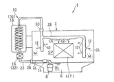
図1は、本発明の第1実施形態に係るヘリコプタ用の動力伝達装置1の潤滑系統図を示す。動力伝達装置1は、ケース2と、変速歯車4とを備えている。ケース2は、動力伝達装置1の外郭を構成する。ケース2に、オイルサンプ6が形成されている。オイルサンプ6は、潤滑用の液体状のオイルOLを貯留する。本実施形態では、オイルサンプ6は、ケース2の底壁の一部(中央部)を下方へ凹ませて形成されている。本実施形態では、オイルサンプ6は、ケース2と一体に形成されている。なお、オイルサンプ6の構成は、これに限定されない。例えば、ケース2の側壁の一部に窪みを設けて、その窪みをオイルサンプ6としてもよい。
FIG. 1 shows a lubrication system diagram of a power transmission device 1 for a helicopter according to the first embodiment of the present invention. The power transmission device 1 includes a
変速歯車4は、ケース2の内部に収納されている。変速歯車4は、動力伝達装置1の回転部材を構成する。変速歯車4は、エンジン(図示せず)の回転を変速して、メインロータ(図示せず)およびテールロータ(図示せず)に伝達する。
The
本実施形態の潤滑対象Tは、ヘリコプタのトランスミッション1の回転部材である。詳細には、潤滑対象Tは、変速歯車4や、歯車が設けられる回転軸体の軸受部である。特に、潤滑対象Tが変速歯車4である場合、その噛合い部にオイルOLを供給することが好ましい。
The lubrication target T of the present embodiment is a rotating member of the transmission 1 of the helicopter. Specifically, the lubrication target T is a
動力伝達装置1は、さらに、潤滑ポンプ8と、潤滑通路10と、供給口12とを備えている。潤滑ポンプ8は、オイルサンプ6からオイルOLを吸引して吐出する。潤滑ポンプ8は、オイルサンプ6内に配置されている。ただし、潤滑ポンプ8は、その全体がオイルサンプ6内に配置されている必要はなく、その吸込口または吸込口に接続される配管がオイルサンプ6内に配置されていればよい。潤滑ポンプ8は、特に限定されるものではないが、例えば、ギヤポンプである。潤滑ポンプ8から吐出されたオイルOLは、潤滑通路10を通って潤滑対象Tに供給される。
The power transmission device 1 further includes a
潤滑通路10を通過したオイルOLは、供給口12から潤滑対象Tに供給される。供給口12は、ケース2の内部空間SPに形成されている。供給口12は、例えば、ジェットノズルである。ただし、供給口12は、これに限定されない。例えば、供給口12は、潤滑通路10を構成する配管に形成される貫通孔であってもよい。供給口12から噴射されたオイルOLの一部は、霧状のオイルミストMとして、ケース2の内部空間SPに留まる。つまり、ケース2の内部空間SPには、オイルミストMが含まれている。オイルOLの残部は、オイルサンプ6に回収される。
The oil OL that has passed through the
潤滑通路10は、潤滑ポンプ8から潤滑対象Tへの供給口12に至るオイルOLの通路である。潤滑通路10は、その途中に種々の機器が設けられ、主として配管で構成されている。ただし、潤滑通路10は、ケース2の壁と一体に形成された内部通路を含んでいてもよい。
The
潤滑通路10は、外部通路部分22と、第1内部通路部分24と、第2内部通路部分26とを有している。外部通路部分22は、ケース2の外部に配置されている。第1内部通路部分24は、ケース2の内部に配置されている。詳細には、第1内部通路部分24は、潤滑ポンプ8の下流側で外部通路部分22の上流側に位置する。第2内部通路部分26も、ケース2の内部に配置されている。詳細には、第2内部通路部分26は、外部通路部分22の下流側で供給口12の上流側に位置する。
The
本実施形態では、外部通路部分22と第1内部通路部分24とが第1貫通部分28を介して連通している。また、外部通路部分22と第2内部通路部分26とが第2貫通部分30を介して連通している。第1および第2貫通部分28,30は、ケース2の壁を貫通する部分である。つまり、本実施形態では、潤滑通路10における潤滑ポンプ8から第1貫通部分28までの部分が第1内部通路部分24を構成する。また、第1貫通部分28から第2貫通部分30までの部分が外部通路部分22を構成する。さらに、第2貫通部分30よりも下流側部分が第2内部通路部分26を構成する。ただし、後述のように、外部通路部分22と内部通路部分24,26との間に、必ずしも貫通部分28,30がある必要はない。
In the present embodiment, the
動力伝達装置1は、さらに、方向制御弁14を備えている。方向制御弁14は、通路内の流体の流れ方向を制御する。方向制御弁14の詳細は後述する。また、動力伝達装置1は、オイルフィルタ16と、オイルクーラ18とを備えている。方向制御弁14は、潤滑ポンプ8の下流側に設けられている。オイルフィルタ16は、オイルOLを濾過する。オイルフィルタ16は、方向制御弁14の下流側に設けられている。オイルクーラ18は、オイルOLを冷却する。オイルクーラ18は、オイルフィルタ16の下流側に配置されている。なお、使用条件によっては、オイルフィルタ16、オイルクーラ18を省略してもよい。
The power transmission device 1 further includes a
本実施形態では、オイルフィルタ16およびオイルクーラ18は、潤滑通路10におけるケース2の外部に配置された部分に設けられている。一方、潤滑ポンプ8、方向制御弁14および供給口12は、ケース2の内部に配置されている。つまり、潤滑ポンプ8と方向制御弁14との間の通路部分も、ケース2の内部に配置されている。
In the present embodiment, the
「潤滑通路10におけるケース2の外部に配置された部分」とは、不具合が発生した際に、ケース2の外部にオイルOLが漏れる部分をいう。つまり、「ケース2の外部に配置された部分」以外の潤滑通路部分では、部品の脱落のような不具合が発生した際に、ケースの内部にオイルが漏れる。外部通路部分22は、前記「潤滑通路10におけるケース2の外部に配置された部分」を含む。例えば、ケース2の側壁に潤滑通路10が一体形成されている場合、ケース2の外側からセンサ、ゲージ等の部品が潤滑通路10に取り付けられると、この通路部分は、「ケース2の外部に配置された部分」、すなわち外部通路部分22に相当する。この場合、外部通路部分22と内部通路部分24,26との間に、貫通部分が存在しないことがある。
The “portion arranged outside the
本実施形態では、接続部32が、ケース2の外部に配置されている。詳細には、潤滑通路10におけるケース2の外部に配置された部分、すなわち外部通路部分22に接続部32が設けられている。本実施形態では、オイルフィルタ16およびオイルクーラ18が接続部32を構成する。接続部32は、例えば、通路の途中に介在される装置、または通路の一部を開口して取り付けられる機器、あるいは通路を構成する配管同士を接続する部分を含む。通路の途中に介在される装置は、例えば、本実施形態のオイルフィルタ16およびオイルクーラ18である。通路の一部を開口して取り付けられる機器は、例えば、外部通路部分22に設けられるオイルジェット(ノズル)、圧力センサ、温度センサ、オイルの流れを視認するための配管窓である。また、前記配管同士を接続する部分は、例えば、配管を接続するフランジ、継手(ジョイント)である。ただし、これらは一例であり、接続部32は、これに限定されない。
In this embodiment, the connecting
方向制御弁14は、接続部32の上流側に設けられている。詳細には、方向制御弁14は、ケース2内の第1内部通路部分24に配置されている。方向制御弁14は、ヘリコプタが運転している状態で、潤滑通路10(第1内部通路部分24)内の油圧P1が所定値V1を超えた状態では潤滑通路10を開放する。方向制御弁14は、ヘリコプタが運転している状態で、潤滑通路10内の油圧P1が所定値V1以下の状態では潤滑通路10(第1内部通路部分24)を閉止する。油圧P1が所定値V1以下となるのは、例えば、ヘリコプタが、通常時からドライラン時となる場合である。ドライランの一例としては、潤滑ポンプ8からのオイルが外部に漏れてオイルサンプ6内の油面が低下し、潤滑ポンプ8の吐出圧が低下したときである。
The
本実施形態では、方向制御弁14は逆止弁である。つまり、方向制御弁(逆止弁)14は、その上流側の圧力が所定値V1を超えたときに潤滑通路10を開放する。この逆止弁14は、図2に示す弁体14aと、閉止力付加部材14bとを有する。閉止力付加部材14bは、弁体14aを閉弁方向に押圧する。閉止力付加部材14bは、例えば、ばねである。ただし、方向制御弁14は、逆止弁に限定されない。方向制御弁14は、オイルOLの流れ方向を制御する弁であればよく、例えば、電磁切換弁であってもよい。
In this embodiment, the
図2は、潤滑通路10の潤滑系統を簡略化して示す。本実施形態では、動力伝達装置1は、さらに、放出通路34を備えている。放出通路34は、潤滑通路10における潤滑ポンプ8と方向制御弁14の間から分岐されている。放出通路34は、潤滑通路10における方向制御弁14の上流側のオイルOLをケース2の内部に放出する。ただし、放出通路34は省略してもよい。
FIG. 2 shows a simplified lubrication system of the
図2に二点鎖線で示すように、放出通路34に絞り部36を設けてもよい。絞り部36は、放出通路34の内部に所定の設定圧V2を発生させる。絞り部36は、例えば、オリフィスである。絞り部36の設定圧V2は、方向制御弁14の所定値V1よりも小さく設定される。放出通路34に絞り部36を設けると、逆止弁(方向制御弁)14の上流側の圧力を、所定値V1よりも高くなるように調整できる。
As shown by the alternate long and short dash line in FIG. 2, the
また、絞り部36の設定圧V2を方向制御弁14の所定値V1よりも小さく設定することで、通常運転時の圧力低下が抑制される。潤滑ポンプ8で昇圧されたオイルOLの圧力は、設定圧V2までは圧力低下なしに速やかに上昇する。オイルOLの圧力が設定圧V2を超えると、オイルOLの一部が絞り部36を通過して放出通路34からケース2内に放出される。オイルOLの圧力が所定値V1を超えると、逆止弁14が開弁される。ただし、絞り部36は省略してもよい。
Further, by setting the set pressure V2 of the
つぎに、本実施形態の動力伝達装置1のオイルOLの流れを詳細に述べる。通常時、オイルサンプ6内のオイルOLが、潤滑ポンプ8により吸引され吐出される。このとき、オイルOLの圧力が設定圧V2に達すると、オイルOLの一部が放出通路34からケース2の内部に放出される。これにより、逆止弁14の入口の圧力が上昇し過ぎるのを防止する。放出通路34から放出されたオイルOLはオイルサンプ6に回収される。オイルOLの圧力が所定値V1に達するまでは、方向制御弁14によりオイルOLは堰き止められる。オイルOLの圧力が所定値V1を超えると、オイルOLは、方向制御弁14を通過し、ケース2の外部のオイルフィルタ16でろ過された後、オイルクーラ18で冷却される。
Next, the flow of the oil OL of the power transmission device 1 of the present embodiment will be described in detail. Normally, the oil OL in the
オイルクーラ18で冷却されたオイルOLは、ケース2の内部に戻され、供給口12から潤滑対象T(変速歯車4)に供給される。供給口12から供給されたオイルOLは、潤滑対象Tを潤滑したのちオイルサンプ6に回収される。また、オイルOLの一部は、供給口12からケース2の内部空間SPに噴射され、内部空間SPにオイルミストMとして残留する。
The oil OL cooled by the
例えば、図2に二点鎖線で示すように、ケース2の外部のオイルクーラ18からオイル漏れが発生した場合、潤滑通路10内の油圧P1が低下し、ドライラン状態になる。この状態で、潤滑通路10内の油圧P1が、所定値V1まで低下すると方向制御弁14が閉止する。これにより、潤滑ポンプ8から潤滑通路10へのオイル供給が方向制御弁14により堰き止められるので、オイルOLがケース2の外部に流出するのを防ぐことができる。その結果、オイルサンプ6内のオイルOLおよび内部空間SPのオイルミストMが流出するのが抑制される。したがって、ドライラン能力の向上(飛行継続時間の増大)を図ることができる。
For example, as shown by the alternate long and short dash line in FIG. 2, when oil leaks from the
また、放出通路34により逆止弁(方向制御弁)14の上流側の圧力が下がる。これにより、逆止弁14の閉止力付加部材14bを小さくすることで、逆止弁14全体を小形化できる。さらに、逆止弁14が作動する圧力V1を下げることが可能となる。したがって、通常運転時の圧力損失が抑制される。
Further, the pressure on the upstream side of the check valve (direction control valve) 14 is reduced by the
オイルクーラ18は、スペース上の問題からケース2内部に配置するのが難しいうえに、ケース2の外部に配置するほうが、熱交換効率がよい。このように、潤滑通路10の一部がケース2の外部に配置された場合でも、上記構成によれば、ドライラン時には、方向制御弁14が閉止することにより、オイルOLがケース2の外部に供給されない。したがって、ケース2の外部にオイルOLが流出しない。
It is difficult to dispose the
図3は、本発明の第2実施形態に係る動力伝達装置1Aの潤滑系統を簡略化して示す系統図である。第2実施形態の動力伝達装置1Aは、潤滑通路10に、後述のオイルリザーバ38および開口40が設けられる点で、第1実施形態の動力伝達装置1と異なっている。以下にその詳細を説明するが、第1実施形態との共通部分については同一の符号を付し、説明を省略する。
FIG. 3 is a system diagram showing a simplified lubrication system of the
第2実施形態の潤滑対象Tは、第1潤滑対象42と、第2潤滑対象44とに分けて示されている。なお、潤滑対象Tの数は、これに限られない。例えば、第2潤滑対象44を省略してもよい。また、潤滑対象Tの数は、3つ以上であってもよい。本実施形態では、第1潤滑対象42は、第2潤滑対象44よりも高速で回転している。特に、第1潤滑対象42は、変速歯車4で最も高速で回転する部分であることが好ましい。例えば、第1潤滑対象42は、エンジン(図示せず)の回転が入力される歯車と、その軸受であることが好ましい。
The lubrication target T of the second embodiment is shown separately as a
第2実施形態の供給口12は、オイルOLを第1潤滑対象42に供給する第1供給口46と、オイルOLを第2潤滑対象44に供給する第2供給口48とを有している。なお、供給口12の数は、これに限らない。例えば、第2潤滑対象44を省略する場合には、第2供給口48を省略してもよい。また、潤滑対象Tの数が3つ以上である場合には、供給口12を3つ以上としてもよい。第1供給口46は、第1潤滑対象42の直上に配置されている。ここで、「直上に配置される」とは、第1潤滑対象42の上方であって、ドライラン時に第1供給口46から重力の影響を受けて滴下されるオイルOLが第1潤滑対象42に到達する範囲に、第1供給口46が配置されることをいう。つまり、「直上」とは、重力により滴下されるオイルOLが第1潤滑対象42に到達する範囲の水平方向のずれを含む。第2実施形態では、第1供給口46は、ドライラン時にオイルOLを第1潤滑対象42に滴下するように構成されている。
潤滑通路10における第1供給口46の上流側に、前記オイルリザーバ38が設けられている。詳細には、潤滑通路10における第1供給口46の上流側で第2供給口48の下流側に、オイルリザーバ38が設けられている。オイルリザーバ38は、ケース2の内部に配置されている。詳細には、オイルリザーバ38は、第2内部通路部分26に設けられている。通常時に、オイルリザーバ38は、内部にオイルOLを保持する。ドライラン時に、オイルリザーバ38の内部のオイルOLが、第1供給口46を介して第1潤滑対象42に滴下される。オイルリザーバ38の容量は、要求されるドライラン能力に応じて適宜設定される。
The
第2実施形態では、オイルリザーバ38は、箱状のタンクとして構成されている。ただし、オイルリザーバ38の構成は、これに限られない。例えば、オイルリザーバ38は、潤滑通路10を構成する配管を拡径して形成されていてもよい。このように、オイルリザーバ38は、その前後の配管よりも通路面積(断面積)が大きく形成され、単位長さ当たり(同一の長さ)のオイルOLの貯留量が、その前後の配管よりも大きく形成されている。また、オイルリザーバ38は、ケース2の側壁や上壁と一体に設けてもよい。
In the second embodiment, the
第2実施形態では、箱状のオイルリザーバ38の上壁38aに入口37が形成され、下壁38bに出口39が形成されている。つまり、開口40に繋がる潤滑通路10がオイルリザーバ38の上壁38aに接続され、第1供給口46に繋がる潤滑通路10がオイルリザーバ38の下壁38bに接続されている。ただし、オイルリザーバ38の構成は、これに限定されない。例えば、オイルリザーバ38の出口39を、下壁38bではなく、側壁38cの下部に設けてもよい。
In the second embodiment, the
潤滑通路10におけるオイルリザーバ38の出口39よりも上流側でオイルリザーバ38の出口39よりも上方に、開口40が設けられている。本実施形態では、潤滑通路10におけるオイルリザーバ38の上流側でオイルリザーバ38よりも上方に、前述の開口40が設けられている。開口40は、ケース2の内部に配置されている。詳細には、開口40は、内部空間SPに形成されている。開口40は、オイルリザーバ38の出口39よりも高い位置にあればよく、オイルリザーバ38自体に設けてもよい。本実施形態のように開口40がオイルリザーバ38よりも上流の潤滑通路10に設けられる場合でも、オイルリザーバ38の直上にある必要はない。すなわち、ここでの「上方」は、鉛直方向における上方(高い位置にあること)を意味し、オイルリザーバ38と開口40は水平方向にずれて配置されていてもよい。第2実施形態では、開口40は、オイルクーラ18の下流側で、第2供給口48とオイルリザーバ38との間に設けられている。
An
開口40は、通常時、オイルOLを噴出するように構成されている。そのため、開口40の下流に潤滑対象Tを配置すれば、通常時に、その潤滑対象Tを潤滑することができる。一方で、開口40は、潤滑通路10内の油圧P1が低下したとき、具体的には、潤滑通路10内の油圧P1がオイルサンプ6(内部空間SP)の圧力P2まで低下したときに、この開口40から潤滑通路10内に空気が取り入れられるように構成されている。第2実施形態では、開口40は、潤滑通路10を構成する配管に設けられた貫通孔である。ただし、開口40は、これに限定されず、配管に設けられた突起状のノズルの孔であってもよい。開口40をノズルで構成すれば、通常時に、開口40から潤滑対象Tにオイルの一部を正確に供給することができる。
The
オイルリザーバ38および開口40は、動力伝達装置1Aのケース2内に収納されている。開口40は、オイルリザーバ38の少なくとも底面(下壁38b)よりも上方で、且つ、第1供給口46よりも上方に配置される。開口40はオイルリザーバ38の上面(上壁38a)よりも上方に配置されることが好ましい。これにより、オイルリザーバ38に保持されたすべてのオイルOLを、ドライラン時に第1潤滑対象42に供給できる。開口40とオイルリザーバ38との間の潤滑通路10は、その一部が開口40よりも上方に位置していてもよい。ただし、この場合、ドライラン時に、潤滑通路10における開口40よりも上方に位置する部分のオイルOLが逆流して、開口40から流出する。したがって、開口40とオイルリザーバ38との間の潤滑通路10は、開口40よりも下方に配置されるのが好ましい。
The
第1供給口46は、オイルリザーバ38の少なくとも上面(上壁38a)よりも下方で、且つ、開口40よりも下方に配置される。なお、ここでの下方は、鉛直方向における下方の位置を指すものであり、水平方向の位置は問わない。ただし、第1供給口46がオイルリザーバ38の底面(下壁38b)よりも上方に配置されると、ドライラン時に、オイルリザーバ38における第1供給口46よりも下方に保持されたオイルOLが第1潤滑対象42に供給されない。したがって、第1供給口46は、オイルリザーバ38の底面(下壁38b)よりも下方に配置されることが好ましい。以上より、開口40がオイルリザーバ38の上面よりも上方に配置され、第1供給口46がオイルリザーバ38の底面よりも下方に配置されることが好ましい。これにより、ドライラン時に、オイルリザーバ38のすべてのオイルOLを第1潤滑対象42に供給できる。第2実施形態の放出通路34にも、第1実施形態と同様の絞り部36を設けてもよい。
The
つぎに、図3、4を用いて、第2実施形態の動力伝達装置1Aの動作を説明する。図3は通常時のオイルOLの流れを示し、図4はドライラン時のオイルOLの流れを示している。図3に示す通常時、オイルサンプ6内のオイルOLが、潤滑ポンプ8により吸引され吐出される。潤滑ポンプ8から吐出されたオイルOLは、潤滑通路10を通って潤滑対象Tに供給される。
Next, the operation of the
本実施形態における、通常時のオイルOLの流れを詳細に述べる。潤滑ポンプ8により吐出されたオイルOLは、ケース2の外部のオイルフィルタ16でろ過された後、オイルクーラ18で冷却される。オイルクーラ18で冷却されたオイルOLは、ケース2の内部に戻され、その一部が第2供給口48から第2潤滑対象44に供給される。なお、通常時には、オイルOLは、潤滑通路10内の油圧を受けて、第2供給口48から噴射される。
The flow of oil OL in the normal state in this embodiment will be described in detail. The oil OL discharged by the
オイルOLは、さらに、潤滑通路10内を流れて、その一部が開口40からケース2の内部空間SPに噴射される。オイルOLの残部は、潤滑通路10内をさらに流れ、オイルリザーバ38に到達する。ここでは、オイルリザーバ38に所定量のオイルOLが保持される。オイルリザーバ38を通過したオイルOLは、第1供給口46から第1潤滑対象42に供給される。なお、通常時には、オイルOLは、潤滑通路10内の油圧を受けて、第1供給口46から噴射される。第1および第2供給口46,48から供給されたオイルOLは、第1潤滑対象42および第2潤滑対象44を潤滑したのちオイルサンプ6に回収される。また、オイルOLの一部は、供給口46,48および開口40から内部空間SPに噴射され、内部空間SPにオイルミストMとして残留する。
The oil OL further flows through the
図4に示すように、ケース2の外部のオイルクーラ18からオイル漏れが発生した場合、潤滑通路10内の油圧P1が低下する。潤滑通路10内の油圧P1が、所定値V1まで低下すると方向制御弁14が閉止する。これにより、潤滑ポンプ8からのオイル供給が停止されるので、オイルOLがケース2の外部にそれ以上流出するのを防ぐことができる。
As shown in FIG. 4, when an oil leak occurs from the
さらに、潤滑通路10内の油圧P1がオイルサンプ6(内部空間SP)の圧力P2まで低下すると、開口40から潤滑通路10内に空気Aが取り入れられる。これにより、潤滑通路10の開口40よりも下流側にあるオイルOLは、重力の影響を受けて、オイルリザーバ38内に入る。また、オイルリザーバ38内のオイルOLは、重力の影響を受けて、第1供給口46から第1潤滑対象42に滴下される。オイルリザーバ38内の油圧P3は、開口40を介してオイルサンプ6(内部空間SP)の圧力P2と同じ状態に保たれるので、安定した滴下潤滑が実現される。
Further, when the oil pressure P1 in the
第2実施形態は、上述の第1実施形態と同様の効果を奏する。さらに、第2実施形態によれば、図3の通常時、潤滑通路10のオイルOLは、オイルリザーバ38を介して第1供給口46から第1潤滑対象42に供給される。また、通常時に、オイルリザーバ38に所定量のオイルOLが保持される。図4のドライラン時、開口40から潤滑通路10内に空気Aが取り入れられる。そうすると、オイルリザーバ38内のオイルOLおよび開口40とオイルリザーバ38の間の潤滑通路10内のオイルOLが、重力の影響を受けて、第1供給口46から第1潤滑対象42に滴下される。このように、共通のオイルリザーバ38で、通常時のオイル潤滑も、ドライラン時の滴下潤滑も可能となる。したがって、簡単な構成で、ドライラン能力の向上を図ることができる。
The second embodiment has the same effect as that of the first embodiment described above. Further, according to the second embodiment, in the normal state of FIG. 3, the oil OL of the
つまり、第2実施形態によれば、ドライラン時に、方向制御弁14を閉止することによりオイルサンプ6内のオイルOLおよび内部空間SPのオイルミストMがケース外部に流出するのを抑制しつつ、オイルリザーバ38内のオイルOLで第1潤滑対象42を滴下潤滑することができる。これにより、ドライラン能力の向上を実現できる。なお、オイルリザーバ38による滴下潤滑は、外部のオイル漏れだけでなく、ケース内部でオイル漏れが発生した場合にも同様に実行される。
That is, according to the second embodiment, during the dry run, the oil OL in the
また、オイルサンプ6、潤滑ポンプ8、潤滑対象Tおよびオイルリザーバ38が、ケース2に収納され、開口40がケース2の内部に配置されている。これにより、図3の通常時は、開口40から噴射されるオイルOLにより、ケース2の内部空間SPに配置された潤滑対象Tに供給することができる。
Further, the
潤滑通路10の開口40が、ケース2の外側に設けられたオイルクーラ18の下流側に設けられている。したがって、通常時、オイルクーラ18で冷却後のオイルOLを第1潤滑対象42に供給することができるほか、潤滑通路10におけるオイルクーラ18とオイルリザーバ38との間から、第2潤滑対象44に冷却後のオイルOLを供給することができる。
The
潤滑通路10におけるオイルリザーバ38の上流側に、第2潤滑対象44にオイルOLを供給する第2供給口48が設けられ、開口40が第2供給口48とオイルリザーバ38との間に設けられている。これにより、ドライラン時に、潤滑の優先度が高い第1潤滑対象42を効果的に潤滑することができる。
A
第1潤滑対象42および第2潤滑対象44が動力伝達装置1Aの回転部材(変速歯車4)であり、第2潤滑対象44よりも高速で回転している高速回転部材を第1潤滑対象42とすることで、ドライラン時に、特に潤滑の優先度が高い高速回転部材を重点的に潤滑することができる。
The
潤滑ポンプ8および方向制御弁14が、オイルサンプ6と第2供給口48との間に設けられ、開口40が第2供給口48とオイルリザーバ38との間に設けられていている。したがって、第2供給口48を開口40よりも下方に配置することで、ドライラン時に、戻りオイルOLにより第2潤滑対象44を潤滑することができる。
A
図3,4の第2実施形態では、開口40は、オイルリザーバ38よりも上流側の潤滑通路10に設けられていたが、開口40は、オイルリザーバ38の上面(上壁38a)に形成されていてもよい。さらに、開口40は、オイルリザーバ38の側壁38cの上部、好ましくは、オイルリザーバ38の高さの2/3よりも上方に形成されてもよい。
In the second embodiment of FIGS. 3 and 4, the
本発明は、以上の実施形態に限定されるものでなく、本発明の要旨を逸脱しない範囲内で、種々の追加、変更または削除が可能である。したがって、そのようなものも本発明の範囲内に含まれる。 The present invention is not limited to the above embodiments, and various additions, changes, or deletions can be made without departing from the gist of the present invention. Therefore, such things are also included within the scope of the present invention.
1,1A 動力伝達装置
2 ケース
4 変速歯車(回転部材)
6 オイルサンプ
8 潤滑ポンプ
10 潤滑通路
12 供給口
14 方向制御弁(逆止弁)
18 オイルクーラ
22 外部通路部分
24 第1内部通路部分
26 第2内部通路部分
32 接続部
34 放出通路
36 絞り部
38 オイルリザーバ
39 オイルリザーバの出口
40 開口
42 第1潤滑対象
44 第2潤滑対象
46 第1供給口
48 第2供給口
M オイルミスト(霧状のオイル)
OL 液体状のオイル
P1 潤滑通路内の油圧
SP 内部空間
V1 所定値
1,1A
6
18 Oil cooler 22
OL Liquid oil P1 Flood control in the lubrication passage SP Internal space V1 Predetermined value
Claims (9)
前記ケースの内部空間に配置されて、前記オイルサンプからオイルを吸引して吐出する潤滑ポンプと、
前記ケースの内部空間に配置されて、前記潤滑ポンプからのオイルを前記回転部材へ噴射する供給口と、
前記潤滑ポンプと前記供給口を接続する潤滑通路と、
前記潤滑通路のうち、前記ケースの外部に配置された部分に設けられた接続部と、
前記ケースの内部空間に配置され、前記潤滑通路における前記潤滑ポンプの下流側で前記接続部の上流側に設けられて、前記潤滑通路内の油圧が所定値を超えた状態では前記潤滑通路を開放し、所定値以下の状態では前記潤滑通路を閉止するように構成された方向制御弁と、
を備えたヘリコプタ用の動力伝達装置。 A case that houses a rotating member and contains mist-like oil in the internal space, and a case that has an oil sump that stores liquid oil.
A lubrication pump that is arranged in the internal space of the case and sucks and discharges oil from the oil sump.
A supply port that is arranged in the internal space of the case and injects oil from the lubrication pump into the rotating member.
A lubrication passage connecting the lubrication pump and the supply port,
A connection portion provided in a portion of the lubrication passage provided outside the case, and
It is arranged in the internal space of the case, is provided on the downstream side of the lubrication pump in the lubrication passage and on the upstream side of the connection portion, and opens the lubrication passage when the oil pressure in the lubrication passage exceeds a predetermined value. However, a directional control valve configured to close the lubrication passage when the value is below a predetermined value,
Power transmission device for helicopters equipped with.
前記所定の設定圧は、前記方向制御弁が閉止する前記所定値よりも低いヘリコプタ用の動力伝達装置。 In the power transmission device according to claim 5, the throttle portion generates a predetermined set pressure inside the discharge passage.
The predetermined set pressure is a power transmission device for a helicopter that is lower than the predetermined value at which the directional control valve is closed.
前記供給口の上流側に設けられたオイルリザーバと、
前記オイルリザーバの出口よりも上流側で、前記オイルリザーバの出口よりも上方に設けられた開口と、を有しているヘリコプタ用の動力伝達装置。 In the power transmission device according to any one of claims 1 to 7, the lubrication passage is
An oil reservoir provided on the upstream side of the supply port and
A power transmission device for a helicopter having an opening provided on the upstream side of the outlet of the oil reservoir and above the outlet of the oil reservoir.
前記ケースの内部空間に配置されて、前記オイルサンプからオイルを吸引して吐出する潤滑ポンプと、
前記ケースの内部空間に配置されて、前記潤滑ポンプからのオイルを前記回転部材へ噴射する供給口と、
前記潤滑ポンプと前記供給口を接続する潤滑通路と、
前記ケースの内部空間に配置されて、前記潤滑通路に設けられた方向制御弁と、を備え、
前記潤滑通路は、前記ケースの外部に配置される外部通路部分と、前記ケースの内部に配置されて前記潤滑ポンプの下流側で前記外部通路部分の上流側に位置する第1内部通路部分と、前記ケースの内部に配置されて前記外部通路部分の下流側で前記供給口の上流側に位置する第2内部通路部分と、を有し、
前記方向制御弁は、前記第1内部通路部分に設けられ、前記第1内部通路部分内の油圧が所定値を超えた状態では前記潤滑通路を開放し、所定値以下の状態では前記第1内部通路部分を閉止するように構成されているヘリコプタ用の動力伝達装置。 A case that houses a rotating member and contains mist-like oil in the internal space, and a case that has an oil sump that stores liquid oil.
A lubrication pump that is arranged in the internal space of the case and sucks and discharges oil from the oil sump.
A supply port that is arranged in the internal space of the case and injects oil from the lubrication pump into the rotating member.
A lubrication passage connecting the lubrication pump and the supply port,
A directional control valve arranged in the internal space of the case and provided in the lubrication passage is provided.
The lubrication passage includes an external passage portion arranged outside the case, a first internal passage portion arranged inside the case and located on the downstream side of the lubrication pump and upstream side of the external passage portion. It has a second internal passage portion that is arranged inside the case and is located on the downstream side of the external passage portion and on the upstream side of the supply port.
The directional control valve is provided in the first internal passage portion, opens the lubrication passage when the oil pressure in the first internal passage portion exceeds a predetermined value, and opens the lubrication passage when the oil pressure in the first internal passage portion exceeds a predetermined value. A power transmission device for a helicopter that is configured to close the passage section.
Priority Applications (5)
| Application Number | Priority Date | Filing Date | Title |
|---|---|---|---|
| JP2017124892A JP6846301B2 (en) | 2017-06-27 | 2017-06-27 | Power transmission device for helicopters |
| EP18824698.7A EP3647206B1 (en) | 2017-06-27 | 2018-06-26 | Power transmission device for helicopter |
| PCT/JP2018/024132 WO2019004178A1 (en) | 2017-06-27 | 2018-06-26 | Power transmission device for helicopter |
| US16/722,354 US11618556B2 (en) | 2017-06-27 | 2019-12-20 | Lubrication pressue control of a power transmission device for helicopter |
| US18/091,102 US20230137698A1 (en) | 2017-06-27 | 2022-12-29 | Power transmission device for helicopter |
Applications Claiming Priority (1)
| Application Number | Priority Date | Filing Date | Title |
|---|---|---|---|
| JP2017124892A JP6846301B2 (en) | 2017-06-27 | 2017-06-27 | Power transmission device for helicopters |
Publications (3)
| Publication Number | Publication Date |
|---|---|
| JP2019006292A JP2019006292A (en) | 2019-01-17 |
| JP2019006292A5 JP2019006292A5 (en) | 2020-04-30 |
| JP6846301B2 true JP6846301B2 (en) | 2021-03-24 |
Family
ID=64741624
Family Applications (1)
| Application Number | Title | Priority Date | Filing Date |
|---|---|---|---|
| JP2017124892A Active JP6846301B2 (en) | 2017-06-27 | 2017-06-27 | Power transmission device for helicopters |
Country Status (4)
| Country | Link |
|---|---|
| US (2) | US11618556B2 (en) |
| EP (1) | EP3647206B1 (en) |
| JP (1) | JP6846301B2 (en) |
| WO (1) | WO2019004178A1 (en) |
Families Citing this family (4)
| Publication number | Priority date | Publication date | Assignee | Title |
|---|---|---|---|---|
| CN111365601A (en) * | 2020-03-31 | 2020-07-03 | 江西晶昊盐化有限公司 | Lime process equipment lubricating system |
| CN112407302A (en) * | 2020-10-30 | 2021-02-26 | 中国直升机设计研究所 | Active anti-bounce oil loss system and method for helicopter transmission system |
| CN112283328B (en) * | 2020-11-04 | 2022-04-12 | 福建中维动力科技股份有限公司 | Oil pump transfer case for pure electric truck |
| FR3134440B1 (en) | 2022-04-07 | 2024-03-15 | Airbus Helicopters | Mechanical system provided with a casing housing above elements to be lubricated or cooled a reservoir of a lubricating fluid system |
Family Cites Families (23)
| Publication number | Priority date | Publication date | Assignee | Title |
|---|---|---|---|---|
| FR2658577A1 (en) * | 1990-02-20 | 1991-08-23 | Aerospatiale | EMERGENCY LUBRICATION DEVICE FOR REDUCER, PARTICULARLY FOR A MAIN TRANSMISSION OF A GIRAVION. |
| US5411116A (en) * | 1994-06-22 | 1995-05-02 | United Technologies Corporation | Self-scavenging, hybrid lubrication subsystem |
| DE19756018A1 (en) * | 1997-12-17 | 1999-06-24 | Porsche Ag | Device for pressurizing and / or lubricating a hydraulic consumer in an internal combustion engine |
| JP3827926B2 (en) * | 1999-07-29 | 2006-09-27 | 本田技研工業株式会社 | Hydraulic circuit and hydraulic control device for automatic transmission of automatic engine stop vehicle |
| FR2831938B1 (en) * | 2001-11-07 | 2004-02-20 | Eurocopter France | LUBRICATION SYSTEM FOR TILTING POWER TRANSMISSION BOX |
| ATE390349T1 (en) | 2005-06-30 | 2008-04-15 | Agusta Spa | HELICOPTER WITH AUXILIARY LUBRICANT OIL CIRCUIT |
| US8459413B2 (en) * | 2007-01-19 | 2013-06-11 | Sirkorsky Aircraft Corporation | Lubrication system with prolonged loss of lubricant operation |
| JP5546311B2 (en) * | 2010-03-29 | 2014-07-09 | アイシン・エィ・ダブリュ株式会社 | Vehicle drive device |
| US20120061184A1 (en) * | 2010-09-14 | 2012-03-15 | Eaton Corporation | Transmission Pump |
| US8702562B2 (en) * | 2010-10-11 | 2014-04-22 | Gm Global Technology Operations | System and method for controlling an automatic engine stop-start based on transmission conditions |
| CA2827626C (en) * | 2011-02-17 | 2018-05-15 | Allison Transmission, Inc. | Modulation control system and method for a hybrid transmission |
| AU2012273001B2 (en) * | 2011-06-22 | 2015-04-23 | Allison Transmission, Inc. | Low level oil detection system and method |
| DE102012214495B3 (en) * | 2012-08-14 | 2013-12-24 | Zf Friedrichshafen Ag | Device for ensuring oil supply of secondary circuit of hydraulic system of gearbox of hybrid powertrain of motor car, has bypass valve closed at predetermined pressure to allow predetermined volumetric flow into secondary circuit |
| JP5899594B2 (en) * | 2012-08-23 | 2016-04-06 | アイシン・エィ・ダブリュ株式会社 | Hydraulic control device for vehicle |
| ITPD20130112A1 (en) * | 2013-04-24 | 2014-10-25 | Carraro Drive Tech S P A | HYDRAULIC CIRCUIT FOR TRANSMISSIONS OF INDUSTRIAL AND AGRICULTURAL VEHICLES |
| JP5967053B2 (en) * | 2013-10-28 | 2016-08-10 | トヨタ自動車株式会社 | Hydraulic control device |
| FR3027998B1 (en) * | 2014-10-31 | 2017-08-25 | Airbus Helicopters | DUAL CIRCUIT RELIABLE LUBRICATION METHOD AND DEVICE OF A MAIN POWER TRANSMISSION BOX OF AN AIRCRAFT |
| US10746284B2 (en) * | 2015-04-21 | 2020-08-18 | Sikorsky Aircraft Corporation | Gearbox lubrication system for aircraft |
| FR3037355B1 (en) * | 2015-06-11 | 2017-05-19 | Airbus Helicopters | TRANSMISSION BOX OF POWER AND AIRCRAFT |
| JP6288059B2 (en) * | 2015-12-09 | 2018-03-07 | トヨタ自動車株式会社 | Power transmission device for vehicle |
| FR3045764B1 (en) * | 2015-12-17 | 2017-12-22 | Airbus Helicopters | SIMPLIFIED ARCHITECTURE BACKUP LUBRICATION DEVICE FOR A MAIN POWER TRANSMISSION BOX OF AN AIRCRAFT |
| US10837329B2 (en) * | 2017-11-16 | 2020-11-17 | GM Global Technology Operations LLC | Flow control system to eliminate air ingestion |
| US11585429B2 (en) * | 2019-09-25 | 2023-02-21 | Neapco Intellectual Property Holdings, Llc | Lubricant supply system and methods for a lubricant supported electric motor |
-
2017
- 2017-06-27 JP JP2017124892A patent/JP6846301B2/en active Active
-
2018
- 2018-06-26 WO PCT/JP2018/024132 patent/WO2019004178A1/en unknown
- 2018-06-26 EP EP18824698.7A patent/EP3647206B1/en active Active
-
2019
- 2019-12-20 US US16/722,354 patent/US11618556B2/en active Active
-
2022
- 2022-12-29 US US18/091,102 patent/US20230137698A1/en active Pending
Also Published As
| Publication number | Publication date |
|---|---|
| EP3647206A4 (en) | 2021-03-24 |
| JP2019006292A (en) | 2019-01-17 |
| US11618556B2 (en) | 2023-04-04 |
| WO2019004178A1 (en) | 2019-01-03 |
| EP3647206B1 (en) | 2023-02-22 |
| EP3647206A1 (en) | 2020-05-06 |
| US20230137698A1 (en) | 2023-05-04 |
| US20200122824A1 (en) | 2020-04-23 |
Similar Documents
| Publication | Publication Date | Title |
|---|---|---|
| JP6846301B2 (en) | Power transmission device for helicopters | |
| US8997935B2 (en) | Continuous supply fluid reservoir | |
| JP4880382B2 (en) | Helicopter with preliminary lubrication circuit | |
| US4169519A (en) | Lubricating device for transmissions or the like in starting condition | |
| EP2261539B1 (en) | Gravity operated valve | |
| CA2688674C (en) | Flow restrictor for lubrication line | |
| CN102734448A (en) | Gearbox with passive lubrication system | |
| JP2005024093A (en) | Device and method for lubrication | |
| EP3854681B1 (en) | Helicopter | |
| EP2166195B1 (en) | Fluid reservoir in a gas turbine engine | |
| US11365800B2 (en) | Lubrication device for helicopter | |
| US20190178119A1 (en) | Lubrication circuit, particularly in an aircraft engine | |
| US11965591B2 (en) | Lubrication device for helicopter | |
| US11835126B2 (en) | Mechanical system provided with a sump receiving, above components to be lubricated or cooled, a tank of a lubricating fluid system | |
| KR101781731B1 (en) | Lubricant circuit having ventilation pipe preventing oil leakage considering position variation | |
| JP5937130B2 (en) | Oil supply system | |
| JP2019011759A (en) | Exhaust turbine supercharger having chamber-shaped oil distribution space | |
| JP2016098845A (en) | Bearing oil supply apparatus and bearing oil supply method | |
| JPS5920917B2 (en) | Emergency oil mist supply device |
Legal Events
| Date | Code | Title | Description |
|---|---|---|---|
| A521 | Request for written amendment filed |
Free format text: JAPANESE INTERMEDIATE CODE: A523 Effective date: 20200318 |
|
| A621 | Written request for application examination |
Free format text: JAPANESE INTERMEDIATE CODE: A621 Effective date: 20200318 |
|
| TRDD | Decision of grant or rejection written | ||
| A01 | Written decision to grant a patent or to grant a registration (utility model) |
Free format text: JAPANESE INTERMEDIATE CODE: A01 Effective date: 20210202 |
|
| A61 | First payment of annual fees (during grant procedure) |
Free format text: JAPANESE INTERMEDIATE CODE: A61 Effective date: 20210301 |
|
| R150 | Certificate of patent or registration of utility model |
Ref document number: 6846301 Country of ref document: JP Free format text: JAPANESE INTERMEDIATE CODE: R150 |
|
| R250 | Receipt of annual fees |
Free format text: JAPANESE INTERMEDIATE CODE: R250 |