EP0443382A1 - Method for cleaning the filtration element of a filter centrifuge - Google Patents
Method for cleaning the filtration element of a filter centrifuge Download PDFInfo
- Publication number
- EP0443382A1 EP0443382A1 EP91101733A EP91101733A EP0443382A1 EP 0443382 A1 EP0443382 A1 EP 0443382A1 EP 91101733 A EP91101733 A EP 91101733A EP 91101733 A EP91101733 A EP 91101733A EP 0443382 A1 EP0443382 A1 EP 0443382A1
- Authority
- EP
- European Patent Office
- Prior art keywords
- base layer
- liquid
- filter
- drum
- filter medium
- Prior art date
- Legal status (The legal status is an assumption and is not a legal conclusion. Google has not performed a legal analysis and makes no representation as to the accuracy of the status listed.)
- Granted
Links
Images
Classifications
-
- B—PERFORMING OPERATIONS; TRANSPORTING
- B04—CENTRIFUGAL APPARATUS OR MACHINES FOR CARRYING-OUT PHYSICAL OR CHEMICAL PROCESSES
- B04B—CENTRIFUGES
- B04B15/00—Other accessories for centrifuges
- B04B15/06—Other accessories for centrifuges for cleaning bowls, filters, sieves, inserts, or the like
Definitions
- the invention relates to a method for cleaning filter media in filter centrifuges according to the preamble of patent claim 1.
- Filter media from filter centrifuges in which the filter cake is removed in batches by means of a peeling and discharge device, have a tendency to increase the filtration resistance, since the base layer remaining after the peeling becomes denser with each peeling process. The base layer must therefore be completely removed from the filter medium after a certain number of peeling or discharge processes.
- the invention is therefore based on the object of specifying a method of the aforementioned type, in which a particular one without additional additional equipment and only with small amounts of liquid thorough cleaning of the filter medium from product residues can be achieved.
- the invention is based on the knowledge that on the one hand the adhesive effect of the solid constituents and on the filter medium is reduced by the saturating penetration and flooding of the base layer with liquid and on the other hand due to the inertia when the drum is braked strongly between the filter medium on the one hand and the solid residues and the liquid on the other hand, shear forces are generated, which cause the base layer to be largely completely detached from the filter medium.
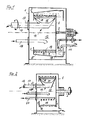
- Fig. 1 shows a filter centrifuge of the type with a siphon or backwashing device.
- a drum 3 is mounted in a housing 1 with a horizontal drum axis of rotation 2.
- the drum consists of a drum base 4, a solid casing 5, a ring cup 6, a rim 7 and a filter medium 8.
- the solid shell 5 and the filter medium 8 enclose a filtrate collecting space 9, which has a through opening 10 arranged in the drum base 4 with the ring cup 6 communicates.
- a liquid supply pipe 11 and a peeling pipe 11a open into the ring cup 6.
- a discharge device 14 Extending into the drum interior 12 is a discharge device 14 which can be pivoted about a pivot axis 13 and carries a peeling knife 15 which extends over the axial length of the drum 3.
- a discharge hopper 16 adjoins the peeling knife 15 and opens into a discharge pipe 17 equipped with a discharge screw (not shown).
- a suspension feed pipe 18 also projects into the drum interior 12.
- suspension is filled into the drum 3 via the suspension feed tube 18, whereupon the solid layer settles on the filter medium 8 during centrifugation and the filtrate flows through the filter medium 8 via the filtrate collecting space 9 and the passage opening 10 into the ring cup 6 where the filtrate can be completely drawn off by means of the peeling tube 11a which can be pivoted to the bottom of the ring cup.
- the solid layer deposited on the filter medium 8 can then be peeled off by swiveling in the peeling knife 15 and discharged via the discharge funnel 16 and the discharge tube 17, the base layer 19 remaining on the filter medium 8, which in particular compresses after repeated peeling processes while increasing the filtration resistance.
- liquid is poured into the ring cup 6 via the liquid feed pipe 16, which passes through the through opening 10 into the filtrate collecting space 9 and then the filter medium 8 and the base layer radially from the outside flows through until the base layer is flooded.
- the drum speed is then reduced with strong negative acceleration, so that the liquid-saturated base layer 19 detaches from the filter medium 8 with all solid particles and slides over the filter medium 8.
- the intensity of the cleaning effect depends on the rotation difference between the liquid loaded with solids in the base layer and the drum.
- product residues that have become lodged under the filter medium or on its support structure (not shown) or on the inner wall of the full casing 5 can also be washed away and removed from the ring cup 6 together with the liquid with the peeling tube 11a.
- the drum speed is determined by how strongly the residues of the base layer adhere to the filter medium.
- the liquid loaded with the solids of the base layer can be discharged in such a way that the solid-liquid mixture collecting in the lower region when the drum speed is slowed down is suctioned off.
- the procedure according to claim 4 is more rational, in which suspension is again filled onto the mixture consisting of solids of the base layer and the liquid, whereupon a normal operating cycle for dewatering a batch of suspension is started.
- the emptying process is particularly simple for centrifuges with a vertical axis of rotation and bottom emptying, in which the mixture consisting of solids of the base layer and liquid is used after braking the drum slowly sinks down and falls out of the drum.
- FIG. 2 shows a filter centrifuge of simple design without a siphon or backwashing device, but the components which correspond to the embodiment according to FIG. 1 are provided with the same reference numerals.
- the liquid supply pipe 20 does not open into a ring cup, but into the drum interior 12.
- the liquid is applied to the base layer 19 from the inside via the liquid supply pipe 20, the speed of the drum 3 and the number of previous peeling processes in accordance with the measures according to claim 2 is determined.
- the procedure for completely cleaning the filter medium from components of the base layer is to be carried out as in the filter centrifuge described with the embodiment according to FIG. 1 with a siphon or backwashing drum.
- the mixture consisting of base layer components and liquid can be discharged, whereby instead of discharging, a renewed supply of suspension can be started for a subsequent normal functional cycle for dewatering a batch of suspension.
Abstract
Description
Die Erfindung betrifft ein Verfahren zur Reinigung von Filtermitteln in Filterzentrifugen gemäß Oberbegriff des Patentanspruchs 1.The invention relates to a method for cleaning filter media in filter centrifuges according to the preamble of
Filtermittel von Filterzentrifugen, bei denen der Filterkuchen chargenweise durch eine Schäl- und Austragvorrichtung entfernt wird, haben die Tendenz eines steigenden Filtrationswiderstandes, da sich die nach dem Schälen verbleibende Grundschicht mit jedem Schälvorgang stärker verdichtet. Die Grundschicht muß daher nach einer bestimmten Anzahl von Schäl- bzw. Austragvorgängen restlos vom Filtermittel entfernt werden.Filter media from filter centrifuges, in which the filter cake is removed in batches by means of a peeling and discharge device, have a tendency to increase the filtration resistance, since the base layer remaining after the peeling becomes denser with each peeling process. The base layer must therefore be completely removed from the filter medium after a certain number of peeling or discharge processes.
Hierzu ist es bekannt, die Grundschicht durch Beaufschlagung mit Druckgas abzublasen. Dabei werden die auf der Oberfläche des Filtermittels befindlichen Produktreste zwar weitgehend entfernt, es bleiben jedoch in das Filtermittel eingedrungene Produktpartikel zurück. Außerdem muß das gasförmige Ausblasmittel wieder vom Feststoff getrennt werden.For this purpose, it is known to blow off the base layer by applying compressed gas. Although the product residues on the surface of the filter medium are largely removed, product particles which have penetrated into the filter medium remain. In addition, the gaseous blowing agent must be separated from the solid.
Aufgrund der Tatsache, daß die unteren Bereiche des Filterkuchens wegen der gegebenen Kapillarkräfte besonders naß sind, bestehen auch starke Haft- bzw. Klebewirkungen, durch die sich das Abblasen der Grundschicht problematisch gestalten kann.Due to the fact that the lower areas of the filter cake are particularly wet due to the given capillary forces, there are also strong adhesive or adhesive effects, which can make the blowing off of the base layer problematic.
Es ist auch bekannt, die Grundschicht durch Aufspritzen von Flüssigkeit unter hohem Druck aus dem Filtermittel zu entfernen. Dabei sind jedoch verhältnismäßig große Flüssigkeitsmengen erforderlich, um den gewünschten Effekt zu erzielen. In der Regel sind große Flüssigkeitsmengen jedoch unerwünscht, weil diese wiederum von Feststoff getrennt oder sogar verdampft werden müssen.It is also known to remove the base layer from the filter medium by spraying liquid under high pressure. However, relatively large amounts of liquid are required to achieve the desired effect. However, large amounts of liquid are generally undesirable because they in turn have to be separated from the solid or even evaporated.
Der Erfindung liegt daher die Aufgabe zugrunde, ein Verfahren der vorgenanten Art anzugeben, bei dem ohne zusätzlichen gerätetechnischen Mehraufwand und nur mit geringen Flüssigkeitsmengen eine besonders gründliche Reinigung des Filtermittels von Produktresten erzielt werden kann.The invention is therefore based on the object of specifying a method of the aforementioned type, in which a particular one without additional additional equipment and only with small amounts of liquid thorough cleaning of the filter medium from product residues can be achieved.
Die Lösung dieser Aufgabe erfolgt durch die im Patentanspruch 1 angegebenen Maßnahmen und Merkmale; die Unteransprüche betreffen vorteilhafte Ausgestaltungen der Erfindung.This object is achieved by the measures and features specified in
Die Erfindung geht dabei von der Erkenntnis aus, daß sich zum einen durch die sättigende Durchsetzung und Überflutung der Grundschicht mit Flüssigkeit die Haftwirkung der Feststoffbestandteile untereinander und am Filtermittel reduziert und zum anderen aufgrund der Massenträgheit beim starken Abbremsen der Trommel zwischen dem Filtermittel einerseits und den Feststoffresten sowie der Flüssigkeit andererseits, Scherkräfte erzeugt werden, die ein weitestgehend vollständiges Ablösen der Grundschicht vom Filtermittel bewirken.The invention is based on the knowledge that on the one hand the adhesive effect of the solid constituents and on the filter medium is reduced by the saturating penetration and flooding of the base layer with liquid and on the other hand due to the inertia when the drum is braked strongly between the filter medium on the one hand and the solid residues and the liquid on the other hand, shear forces are generated, which cause the base layer to be largely completely detached from the filter medium.
Ausführungsformen der Erfindung werden anhand der Zeichnung erläutert; es zeigen:
- Fig. 1
- in schematischer Darstellung eine Filterzentrifuge mit einem das Filtermittel umgebenden Vollmantel und einer Ringtasse und
- Fig. 2
- in schematischer Darstellung eine Filterzentrifuge mit einfachem Aufbau
- Fig. 1
- a schematic representation of a filter centrifuge with a solid jacket surrounding the filter medium and a ring cup and
- Fig. 2
- a filter centrifuge with a simple structure in a schematic representation
Die Fig. 1 zeigt eine Filterzentrifuge der Bauart mit einer Siphon- oder Rückspüleinrichtung. In einem Gehäuse 1 ist mit horizontaler Trommel-Drehachse 2 eine Trommel 3 gelagert. Die Trommel besteht dabei aus einem Trommelboden 4, einem Vollmantel 5, einer Ringtasse 6, einem Bordring 7 sowie einem Filtermittel 8. Der Vollmantel 5 und das Filtermittel 8 schließen einen Filtratsammelraum 9 ein, der über eine im Trommelboden 4 angeordnete Durchgangsöffnung 10 mit der Ringtasse 6 in Verbindung steht. In die Ringtasse 6 mündet ein Flüssigkeitszufuhrrohr 11 sowie ein Schälrohr 11a.Fig. 1 shows a filter centrifuge of the type with a siphon or backwashing device. A drum 3 is mounted in a
In den Trommelinnenraum 12 ragt eine um eine Schwenkachse 13 schwenkbare Austragsvorrichtung 14, die ein über die axiale Länge der Trommel 3 sich erstreckendes Schälmesser 15 trägt. An das Schälmesser 15 schließt sich ein Austragstrichter 16 an, der in ein mit einer Austragschnecke (nicht dargestellt) bestücktes Austragrohr 17 mündet. In den Trommelinnnenraum 12 ragt ferner ein Suspensionszufuhrrohr 18.Extending into the
Auf dem Filtermittel 8 befindet sich eine Grundschicht 19 aus Feststoffmaterial, deren Stärke sich durch die radial äußerste Schwenkstellung des Schälmessers 15 beim Austragvorgang bestimmt. In der dargestellten Stellung befindet sich das Schälmesser 15 in einer von der Grundschichtoberfläche wieder zurückgeschwenkten Stellung.There is a
Im Betrieb der Filterzentrifuge wird über das Suspensionszufuhrrohr 18 Suspension in die Trommel 3 gefüllt, worauf sich während des zentrifugierens auf dem Filtermittel 8 die Feststoffschicht absetzt und das Filtrat durch das Filtermittel 8 über den Filtratsammelraum 9 und die Durchgangsöffnung 10 in die Ringtasse 6 strömt, von wo das Filtrat mittels des bis zum Grund der Ringtasse einschwenkbaren Schälrohres 11a vollständig abgezogen werden kann. Die sich auf dem Filtermittel 8 abgesetzte Feststoffschicht kann anschließend durch Einschwenken des Schälmessers 15 abgeschält und über den Austragtrichter 16 und das Austragrohr 17 ausgetragen werden, wobei auf dem Filtermittel 8 die Grundschicht 19 verbleibt, die sich insbesondere nach mehrmaligen Schälvorgängen unter Erhöhung des Filtrationswiderstandes verdichtet.During operation of the filter centrifuge, suspension is filled into the drum 3 via the
In der Betriebsphase, in der die Grundschicht 19 vom Filtermittel 8 entfernt werden soll, wird über das Flüssigkeitszufuhrrohr 16 in die Ringtasse 6 Flüssigkeit eingefüllt, die über die Durchgangsöffnung 10 in den Filtratsammelraum 9 gelangt und sodann das Filtermittel 8 und die Grundschicht radial von außen nach innen durchströmt, bis die Grundschicht überflutet ist.In the operating phase, in which the
Die Trommeldrehzahl wird anschließend mit starker negativer Beschleunigung reduziert, so daß sich die mit Flüssigkeit gesättigte Grundschicht 19 vom Filtermittel 8 mit allen Feststoffpartikeln löst und über das Filtermittel 8 gleitet. Die Intensität der Reinigungswirkung hängt dabei von der Rotationsdifferenz zwischen der mit Feststoffen der Grundschicht beladenen Flüssigkeit und der Trommel ab.The drum speed is then reduced with strong negative acceleration, so that the liquid-
Bei diesem Vorgang können auch Produktreste, die sich unter dem Filtermittel oder an dessen Stützstruktur (nicht dargestellt) oder an der Innenwandung des Vollmantels 5 festgesetzt haben, weggespült und zusammen mit der Flüssigkeit mit dem Schälrohr 11a aus der Ringtasse 6 abgezogen werden.During this process, product residues that have become lodged under the filter medium or on its support structure (not shown) or on the inner wall of the
Während des Rückspülens, bzw. während der überflutung der Grundschicht mit Flüssigkeit bestimmt sich die Trommeldrehzahl danach, wie stark die Rückstände der Grundschicht auf dem Filtermittel haften.During backwashing or during the flooding of the base layer with liquid, the drum speed is determined by how strongly the residues of the base layer adhere to the filter medium.
In hartnäckigen Fällen kann das erfindungsgemäße Verfahren wiederholt werden.In stubborn cases, the method according to the invention can be repeated.
Der Austrag der mit den Feststoffen der Grundschicht beladenen Flüssigkeit kann in der Weise erfolgen, daß das bei verlangsamter Trommeldrehzahl sich im unteren Bereich sammelnde Feststoff-Flüssigkeitsgemisch abgesaugt wird. Rationeller ist jedoch die Verfahrensweise nach Patentanspruch 4, bei dem auf das aus Feststoffen der Grundschicht und der Flüssigkeit bestehende Gemisch erneut Suspension gefüllt wird, worauf ein normaler Funktionszyklus zum Entwässern einer Charge von Suspension in Gang gesetzt wird.The liquid loaded with the solids of the base layer can be discharged in such a way that the solid-liquid mixture collecting in the lower region when the drum speed is slowed down is suctioned off. However, the procedure according to claim 4 is more rational, in which suspension is again filled onto the mixture consisting of solids of the base layer and the liquid, whereupon a normal operating cycle for dewatering a batch of suspension is started.
In besonders einfacher Weise gestaltet sich der Entleerungsvorgang bei Zentrifugen mit vertikaler Drehachse und Untenentleerung, bei der das aus Feststoffen der Grundschicht und aus Flüssigkeit bestehende Gemisch nach dem Abbremsen der Trommel langsam nach unten sinkt und aus der Trommel fällt.The emptying process is particularly simple for centrifuges with a vertical axis of rotation and bottom emptying, in which the mixture consisting of solids of the base layer and liquid is used after braking the drum slowly sinks down and falls out of the drum.
Die Fig. 2 zeigt eine Filterzentrifuge einfacher Bauart ohne Siphon- oder Rückspüleinrichtung, wobei aber die Bauteile, die der Ausführungsform nach Fig. 1 entsprechen, mit den gleichen Bezugszeichen versehen sind. In Abweichung zu der Ausführungsform nach Fig. 1 mündet das Flüssigkeitszufuhrrohr 20 nicht in eine Ringtasse, sondern in den Trommelinnenraum 12.FIG. 2 shows a filter centrifuge of simple design without a siphon or backwashing device, but the components which correspond to the embodiment according to FIG. 1 are provided with the same reference numerals. In contrast to the embodiment according to FIG. 1, the
In der Betriebsphase, in der die Grundschicht 19 vom Filtermittel 8 entfernt werden soll, wird die Flüssigkeit über das Flüssigkeitszufuhrrohr 20 von innen auf die Grundschicht 19 aufgegeben, wobei die Drehzahl der Trommel 3 und die Anzahl der vorangegangenen Schälvorgänge nach Maßgabe der Maßnahmen nach Patentanspruch 2 bestimmt wird. Nach der sättigenden Beaufschlagung und Überflutung der Grundschicht 19 mit Flüssigkeit ist das Vefahren zur vollständigen Reinigung des Filtermittels von Bestandteilen der Grundschicht wie bei der zu der Ausführungsform nach Fig 1 beschriebenen Filterzentrifuge mit Siphon - oder Rückspültrommel durchzuführen.In the operating phase, in which the
In zur Ausführungsform nach Fig. 1 entsprechender Weise kann das Austragen des aus Grundschichtbestandteilen und Flüssigkeit bestehenden Gemisches erfolgen, wobei anstelle des Austragens auch eine erneute Zuführung von Suspension für einen nachfolgenden normalen Funktionszyklus zum Entwässern einer Charge von Suspension in Gang gesetzt werden kann.In a manner corresponding to the embodiment according to FIG. 1, the mixture consisting of base layer components and liquid can be discharged, whereby instead of discharging, a renewed supply of suspension can be started for a subsequent normal functional cycle for dewatering a batch of suspension.
Claims (4)
Applications Claiming Priority (2)
| Application Number | Priority Date | Filing Date | Title |
|---|---|---|---|
| DE4004763 | 1990-02-15 | ||
| DE4004763 | 1990-02-15 |
Publications (2)
| Publication Number | Publication Date |
|---|---|
| EP0443382A1 true EP0443382A1 (en) | 1991-08-28 |
| EP0443382B1 EP0443382B1 (en) | 1994-07-27 |
Family
ID=6400254
Family Applications (1)
| Application Number | Title | Priority Date | Filing Date |
|---|---|---|---|
| EP91101733A Expired - Lifetime EP0443382B1 (en) | 1990-02-15 | 1991-02-08 | Method for cleaning the filtration element of a filter centrifuge |
Country Status (4)
| Country | Link |
|---|---|
| EP (1) | EP0443382B1 (en) |
| JP (1) | JPH04219156A (en) |
| DE (1) | DE59102298D1 (en) |
| ES (1) | ES2057619T3 (en) |
Cited By (4)
| Publication number | Priority date | Publication date | Assignee | Title |
|---|---|---|---|---|
| WO2002076621A1 (en) * | 2001-03-23 | 2002-10-03 | Aventis Pharma Deutschland Gmbh | Horizontal solid-bowl centrifuge with cleaning-in-place nozzles |
| CN106694246A (en) * | 2016-12-26 | 2017-05-24 | 江苏迈达新材料股份有限公司 | Centrifugal material conveying device for 2,6-Di-tert-butyl-4-methylphenol |
| CN113286922A (en) * | 2019-01-17 | 2021-08-20 | 松下知识产权经营株式会社 | Washing machine and control method thereof |
| CN114011591A (en) * | 2021-09-18 | 2022-02-08 | 安徽东至广信农化有限公司 | Centrifugal machine for producing glyphosate and use method thereof |
Citations (4)
| Publication number | Priority date | Publication date | Assignee | Title |
|---|---|---|---|---|
| US1761593A (en) * | 1927-03-12 | 1930-06-03 | Sharples Specialty Co | Centrifugal treatment of substances |
| DE1062633B (en) * | 1958-07-14 | 1959-07-30 | Westfalia Separator Ag | Method and device for cleaning centrifuge drums with outlet openings on the drum circumference |
| FR2380820A1 (en) * | 1977-02-22 | 1978-09-15 | Escher Wyss Sa | METHOD AND DEVICE FOR REGENERATION OF THE FILTER LAYER OF A SCALING CENTRIFUGE |
| GB2129327A (en) * | 1982-10-29 | 1984-05-16 | Sulzer Escher Wyss Ltd | Centrifugal strainer cleaning |
Family Cites Families (4)
| Publication number | Priority date | Publication date | Assignee | Title |
|---|---|---|---|---|
| JPS5617497B1 (en) * | 1978-06-26 | 1981-04-22 | ||
| JPS6172144A (en) * | 1984-09-13 | 1986-04-14 | 東陶機器株式会社 | Toilet bowl washing apparatus |
| JPS6417935A (en) * | 1987-07-14 | 1989-01-20 | Inax Corp | Washer for closet |
| JPH0437676U (en) * | 1990-07-20 | 1992-03-30 |
-
1991
- 1991-02-08 EP EP91101733A patent/EP0443382B1/en not_active Expired - Lifetime
- 1991-02-08 ES ES91101733T patent/ES2057619T3/en not_active Expired - Lifetime
- 1991-02-08 DE DE59102298T patent/DE59102298D1/en not_active Expired - Fee Related
- 1991-02-12 JP JP3018790A patent/JPH04219156A/en active Pending
Patent Citations (4)
| Publication number | Priority date | Publication date | Assignee | Title |
|---|---|---|---|---|
| US1761593A (en) * | 1927-03-12 | 1930-06-03 | Sharples Specialty Co | Centrifugal treatment of substances |
| DE1062633B (en) * | 1958-07-14 | 1959-07-30 | Westfalia Separator Ag | Method and device for cleaning centrifuge drums with outlet openings on the drum circumference |
| FR2380820A1 (en) * | 1977-02-22 | 1978-09-15 | Escher Wyss Sa | METHOD AND DEVICE FOR REGENERATION OF THE FILTER LAYER OF A SCALING CENTRIFUGE |
| GB2129327A (en) * | 1982-10-29 | 1984-05-16 | Sulzer Escher Wyss Ltd | Centrifugal strainer cleaning |
Cited By (6)
| Publication number | Priority date | Publication date | Assignee | Title |
|---|---|---|---|---|
| WO2002076621A1 (en) * | 2001-03-23 | 2002-10-03 | Aventis Pharma Deutschland Gmbh | Horizontal solid-bowl centrifuge with cleaning-in-place nozzles |
| US8574143B2 (en) | 2001-03-23 | 2013-11-05 | Sanofi-Aventis Deutschland Gmbh | Compliant design of a horizontal solid-bowl centrifuge with cleaning-in-place nozzles |
| CN106694246A (en) * | 2016-12-26 | 2017-05-24 | 江苏迈达新材料股份有限公司 | Centrifugal material conveying device for 2,6-Di-tert-butyl-4-methylphenol |
| CN106694246B (en) * | 2016-12-26 | 2019-04-23 | 江苏迈达新材料股份有限公司 | A kind of centrifugal material conveying device for 2,6 di tert butyl 4 methyl phenol |
| CN113286922A (en) * | 2019-01-17 | 2021-08-20 | 松下知识产权经营株式会社 | Washing machine and control method thereof |
| CN114011591A (en) * | 2021-09-18 | 2022-02-08 | 安徽东至广信农化有限公司 | Centrifugal machine for producing glyphosate and use method thereof |
Also Published As
| Publication number | Publication date |
|---|---|
| ES2057619T3 (en) | 1994-10-16 |
| DE59102298D1 (en) | 1994-09-01 |
| JPH04219156A (en) | 1992-08-10 |
| EP0443382B1 (en) | 1994-07-27 |
Similar Documents
| Publication | Publication Date | Title |
|---|---|---|
| DE2260461C3 (en) | Filter centrifuge | |
| DE4023497C2 (en) | Continuous pressure filter | |
| EP0454045B1 (en) | Centrifugal drier | |
| DE1088469B (en) | Method and device for the continuous separation of solids from liquids and their removal from the filter | |
| EP1468744B1 (en) | Pusher centrifuge with rotatable cone for pre-accelerating the mixture | |
| DE102011010621A1 (en) | Solid bowl centrifuge with drying of the solids cake | |
| DE2328258A1 (en) | PROCESS FOR SEPARATING LIQUIDS FROM A SOLID-LIQUID MIXTURE AND DEVICE FOR CARRYING OUT THE PROCESS | |
| DE3626314C2 (en) | Device for separating suspensions | |
| EP0672459B1 (en) | Filter centrifuge | |
| WO1994001219A1 (en) | Process and device of gravity concentration of solid materials | |
| EP0443382A1 (en) | Method for cleaning the filtration element of a filter centrifuge | |
| DE2834491C2 (en) | Sieve centrifuge with curved sieve pockets | |
| DE3817126C2 (en) | ||
| DE4104752C2 (en) | ||
| EP0155632B1 (en) | Method and apparatus for separating material mixtures | |
| DE3336132C2 (en) | ||
| DE19616040C2 (en) | Filtrate discharge for a solid bowl centrifuge | |
| DE2008831A1 (en) | Move the rotary filter device and filter | |
| DE4215061A1 (en) | Sludge drying - using centrifuge for initial water extn. followed by feeding DC current through electrodes pressed against caked sludge for scraper extn. | |
| DE976357C (en) | Horizontal solid bowl centrifuge | |
| DE2930312C2 (en) | Sieve centrifuge | |
| DE4231820A1 (en) | Screen drum-type centrifuge - has fluid blasting system for residual layer removal from screen drum | |
| DE10228231C1 (en) | Device for washing filter bag of pushing bag centrifuge comprises washing nozzle for liquid washing medium in solid material chamber of housing just in front of end of drum | |
| DE1021297B (en) | Centrifuge drum for screw separator centrifuges | |
| DE1773147B2 (en) | Method and device for separating the insoluble constituents of a bitumen sample to determine the content and the granulometric composition |
Legal Events
| Date | Code | Title | Description |
|---|---|---|---|
| PUAI | Public reference made under article 153(3) epc to a published international application that has entered the european phase |
Free format text: ORIGINAL CODE: 0009012 |
|
| AK | Designated contracting states |
Kind code of ref document: A1 Designated state(s): CH DE ES FR GB IT LI |
|
| 17P | Request for examination filed |
Effective date: 19920125 |
|
| 17Q | First examination report despatched |
Effective date: 19921221 |
|
| GRAA | (expected) grant |
Free format text: ORIGINAL CODE: 0009210 |
|
| AK | Designated contracting states |
Kind code of ref document: B1 Designated state(s): CH DE ES FR GB IT LI |
|
| ET | Fr: translation filed | ||
| GBT | Gb: translation of ep patent filed (gb section 77(6)(a)/1977) |
Effective date: 19940727 |
|
| REF | Corresponds to: |
Ref document number: 59102298 Country of ref document: DE Date of ref document: 19940901 |
|
| REG | Reference to a national code |
Ref country code: ES Ref legal event code: FG2A Ref document number: 2057619 Country of ref document: ES Kind code of ref document: T3 |
|
| ITF | It: translation for a ep patent filed |
Owner name: SOCIETA' ITALIANA BREVETTI S.P.A. |
|
| PLBE | No opposition filed within time limit |
Free format text: ORIGINAL CODE: 0009261 |
|
| STAA | Information on the status of an ep patent application or granted ep patent |
Free format text: STATUS: NO OPPOSITION FILED WITHIN TIME LIMIT |
|
| 26N | No opposition filed | ||
| PGFP | Annual fee paid to national office [announced via postgrant information from national office to epo] |
Ref country code: GB Payment date: 19970121 Year of fee payment: 7 |
|
| PGFP | Annual fee paid to national office [announced via postgrant information from national office to epo] |
Ref country code: FR Payment date: 19970214 Year of fee payment: 7 |
|
| PGFP | Annual fee paid to national office [announced via postgrant information from national office to epo] |
Ref country code: ES Payment date: 19970219 Year of fee payment: 7 |
|
| PG25 | Lapsed in a contracting state [announced via postgrant information from national office to epo] |
Ref country code: GB Free format text: LAPSE BECAUSE OF NON-PAYMENT OF DUE FEES Effective date: 19980208 |
|
| PG25 | Lapsed in a contracting state [announced via postgrant information from national office to epo] |
Ref country code: ES Free format text: LAPSE BECAUSE OF EXPIRATION OF PROTECTION Effective date: 19980209 |
|
| PG25 | Lapsed in a contracting state [announced via postgrant information from national office to epo] |
Ref country code: FR Free format text: THE PATENT HAS BEEN ANNULLED BY A DECISION OF A NATIONAL AUTHORITY Effective date: 19980228 |
|
| GBPC | Gb: european patent ceased through non-payment of renewal fee |
Effective date: 19980208 |
|
| REG | Reference to a national code |
Ref country code: FR Ref legal event code: ST |
|
| REG | Reference to a national code |
Ref country code: CH Ref legal event code: PUE Owner name: KRAUSS-MAFFEI AKTIENGESELLSCHAFT TRANSFER- MANNESM |
|
| REG | Reference to a national code |
Ref country code: ES Ref legal event code: FD2A Effective date: 20000301 |
|
| PGFP | Annual fee paid to national office [announced via postgrant information from national office to epo] |
Ref country code: CH Payment date: 20020220 Year of fee payment: 12 |
|
| PGFP | Annual fee paid to national office [announced via postgrant information from national office to epo] |
Ref country code: DE Payment date: 20020422 Year of fee payment: 12 |
|
| REG | Reference to a national code |
Ref country code: CH Ref legal event code: PUE Owner name: MANNESMANN DEMAG KRAUSS-MAFFEI AG TRANSFER- KRAUSS |
|
| PG25 | Lapsed in a contracting state [announced via postgrant information from national office to epo] |
Ref country code: LI Free format text: LAPSE BECAUSE OF NON-PAYMENT OF DUE FEES Effective date: 20030228 Ref country code: CH Free format text: LAPSE BECAUSE OF NON-PAYMENT OF DUE FEES Effective date: 20030228 |
|
| PG25 | Lapsed in a contracting state [announced via postgrant information from national office to epo] |
Ref country code: DE Free format text: LAPSE BECAUSE OF NON-PAYMENT OF DUE FEES Effective date: 20030902 |
|
| REG | Reference to a national code |
Ref country code: CH Ref legal event code: PL |
|
| PG25 | Lapsed in a contracting state [announced via postgrant information from national office to epo] |
Ref country code: IT Free format text: LAPSE BECAUSE OF NON-PAYMENT OF DUE FEES Effective date: 20050208 |