EP0442741B1 - Solid oxide fuel cell - Google Patents
Solid oxide fuel cell Download PDFInfo
- Publication number
- EP0442741B1 EP0442741B1 EP91301209A EP91301209A EP0442741B1 EP 0442741 B1 EP0442741 B1 EP 0442741B1 EP 91301209 A EP91301209 A EP 91301209A EP 91301209 A EP91301209 A EP 91301209A EP 0442741 B1 EP0442741 B1 EP 0442741B1
- Authority
- EP
- European Patent Office
- Prior art keywords
- fuel
- gas flow
- oxidizing gas
- gas supply
- flow passages
- Prior art date
- Legal status (The legal status is an assumption and is not a legal conclusion. Google has not performed a legal analysis and makes no representation as to the accuracy of the status listed.)
- Expired - Lifetime
Links
Images


Classifications
-
- H—ELECTRICITY
- H01—ELECTRIC ELEMENTS
- H01M—PROCESSES OR MEANS, e.g. BATTERIES, FOR THE DIRECT CONVERSION OF CHEMICAL ENERGY INTO ELECTRICAL ENERGY
- H01M8/00—Fuel cells; Manufacture thereof
- H01M8/24—Grouping of fuel cells, e.g. stacking of fuel cells
- H01M8/241—Grouping of fuel cells, e.g. stacking of fuel cells with solid or matrix-supported electrolytes
- H01M8/2425—High-temperature cells with solid electrolytes
- H01M8/2435—High-temperature cells with solid electrolytes with monolithic core structure, e.g. honeycombs
-
- Y—GENERAL TAGGING OF NEW TECHNOLOGICAL DEVELOPMENTS; GENERAL TAGGING OF CROSS-SECTIONAL TECHNOLOGIES SPANNING OVER SEVERAL SECTIONS OF THE IPC; TECHNICAL SUBJECTS COVERED BY FORMER USPC CROSS-REFERENCE ART COLLECTIONS [XRACs] AND DIGESTS
- Y02—TECHNOLOGIES OR APPLICATIONS FOR MITIGATION OR ADAPTATION AGAINST CLIMATE CHANGE
- Y02E—REDUCTION OF GREENHOUSE GAS [GHG] EMISSIONS, RELATED TO ENERGY GENERATION, TRANSMISSION OR DISTRIBUTION
- Y02E60/00—Enabling technologies; Technologies with a potential or indirect contribution to GHG emissions mitigation
- Y02E60/30—Hydrogen technology
- Y02E60/50—Fuel cells
Definitions
- the present invention relates to solid oxide fuel cells.
- fuel cells have been noted as power generating equipments. Since the fuel cell is an equipment capable of directly converting chemical energy possessed by fuel to electric energy, and the fuel cell is free from limitation of Carnot's cycle, the cell is a very promising technique owing to its high energy conversion efficiency, wide latitude of fuels to be used (naphtha, natural gas, methanol, coal reformed gas, heavy oil and the like), less public nuisance, and high electric power generating efficiency without being affected by scales of installations.
- the solid oxide fuel cell (referred to as "SOFC” hereinafter) operates at high temperatures of 1,000°C or more, reaction on electrodes is extremely high. Thus, completely no catalyst of a noble metal such as expensive platinum is necessary. In addition, since the SOFC has low polarization and relatively high output voltage, its energy conversion efficiency is conspicuously higher than that in the other fuel cells. Furthermore, since their constituent materials are all solid, the SOFC is stable and has long use life.
- the SOFC is composed of an air electrode, a solid electrolyte and a fuel electrode.
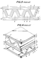
- Fig. 5 is a partial front elevation illustrating one example of such a solid oxide fuel cell.
- This SOFC is of a monolithic design referred to as "Co-flow model" of Argonne type first proposed by Argonne National Laboratory.
- a number of air electrode films 6, which nave an inverted V-shaped section, are provided in opposition to the flat plate-like air electrode films 1 to form a number of oxidizing gas flow passages 8 in a direction orthogonal to the paper.
- These fuel gas flow passages 7 and the oxidizing gas flow passages 8 are combined with one another in the form of a mosaic, and a wavy solid electrolyte film 5 is formed between the fuel electrode films 4 and the air electrode films 6.
- a wavy solid electrolyte film 5 is formed between the fuel electrode films 4 and the air electrode films 6.
- the power generation is performed among these films.
- the films are shown only in one row for the sake of simplicity in Fig. 5, a number of the laminates shown in Fig. 5 are piled one upon another to form a number of gas flow passages in the form of a honeycomb.
- Fig. 6 illustrates a SOFC of the Argonne type which is similar to that of Fig. 5, but referred to as "Cross flow model”.
- This SOFC is composed of flat plate-like laminates 50 and 51 alternately laminated.
- the former laminate 50 is similar to that shown in Fig. 5, and the laminate 51 is formed by arranging successively a flat plate-like fuel electrode film 3, a flat plate-like solid electrolyte film 15 and a flat plate-like air electrode film 1 arranged in parallel with one another with a predetermined interval.
- a wavy fuel electrode film 14 In each space between the two flat plate-like fuel electrode films 3 is arranged a wavy fuel electrode film 14 to form fuel gas flow passages 17 into which a fuel gas is supplied as shown by arrows A.
- a wavy air electrode film 16 to form oxidizing gas flow passages 18 into which an oxidizing gas is supplied as shown by arrows B.
- the fuel gas flow passage 17 and the oxidizing gas flow passage 18 are crossed by a predetermined angle, for example, 90°.
- the flat plate-like fuel electrode film 3 there are interposed the flat plate-like solid electrolyte film 15 and the flat plate-like air electrode film 1 in this order. The power generation is performed in these interposed films.
- the present invention is to provide the solid oxide fuel cell comprising a plurality of flat plate-like laminates spaced substantially in parallel with one another, each of the laminates having one surface covered with a flat plate-like air electrode film and the other surface covered with a flat plate-like fuel electrode film, a plurality of oxidizing gas flow passages arranged between the adjacent flat plate-like laminates and facing the flat plate-like air electrode film, a plurality of fuel gas flow passages arranged between the adjacent flat plate-like laminates and facing the flat plate-like fuel electrode film, and at least air electrode films, solid electrolyte films and fuel electrode films interposed between the oxidizing gas flow passage and the adjacent fuel gas flow passage, wherein oxidizing gas supply pipes are each extended from one end opening of each of the oxidizing gas flow passages into the interior thereof to feed oxidizing gas into the oxidizing gas flow passage so that the oxidizing gas flows back along the passage in contact with the air electrode films, closure members each close the other end of each of the oxidizing gas
- the "air electrode films” are identical with or different from the “flat plate-like air electrode films", and further the “fuel electrode films” are identical with or different from the “flat plate-like fuel electrode films”.
- the "solid electrolyte film” is located between the flat plate-like air electrode film and the flat plate-like fuel electrode film, and constitutes a part of the "flat plate-like laminates".
- the "solid electrolyte film” does not constitute a part of the "flat plate-like laminate", but is located between the adjacent flat plate-like laminates.
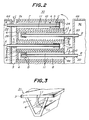
- Fig. 1 is a perspective view of the SOFC according to an embodiment of the present invention, snowing only part of one layer in an enlarged scale for the sake of convenience in explanation.
- Fig. 2 is a partial sectional view of this SOFC.
- a fuel gas supply pipe 10 is provided extending from an opening 7a at one end (on the side of a viewer in Fig. 1 and on the left side of Fig. 2) of each of fuel gas flow passages 7 to the other end thereof.
- the fuel gas supply pipe 10 is supported by three radial ribs 11 in this embodiment. The number of the ribs 11 is of course arbitrary.
- a closure member 24 is provided at the other end of each of the fuel gas flow passages 7 having the fuel gas supply pipe 10 inserted therein, and prevents the fuel gas from escaping therefrom.
- a base portion of the fuel gas supply pipe 10 is exposed in a fuel gas supply chamber 34 defined by a partition wall 64, and a forward end of the fuel gas supply pipe 10 is fixed close to the closure member 24.
- an oxidizing gas supply pipe 20 is provided extending from an opening 8a at one end of each of the oxidizing gas flow passages 8 toward the other end, and supported by three radial ribs 11.
- a closure member 26 is provided at the other end of the oxidizing gas flow passage 8 having the oxidizing gas supply pipe 20 inserted thereinto, and prevents the oxidizing gas from escaping.
- a base portion of the oxidizing gas supply pipe 20 is exposed in an oxidizing gas supply chamber 36 defined by a partition wall 66, and a forward end of the oxidizing gas supply pipe 20 is fixed close to the closure member 26.
- an oxidizing gas is supplied from the oxidizing gas supply chamber 36 into the oxidizing supply pipes 20 as shown by arrows B.
- the oxidizing gas leaves the forward ends of the oxidizing gas supply pipe 20 and is turned at the closure member in the reverse directions.
- the oxidizing gas then flows between the oxidizing gas supply pipe 20 and the air electrode 6, and leaves the end opening 8a as shown by arrows D.
- This fuel cell is so designed that the oxidizing gas is caused to flow by pressure difference between the exhaust gas combustion chamber 30 and the oxidizing gas supply chamber 36.
- the used oxidizing gas whose concentration has been lowered owing to utilization for the generation of the electric power is thus caused to flow into the exhaust gas combustion chamber 30.
- An interconnector 2 is provided between the flat plate-like fuel electrode film 3 and the flat plate-like air electrode film 1 to connect respective layers in series. Finally, a load is connected between upper and lower ends of the stack to extract electric power.
- the air electrode films 1 and 6 may be made of LaMnO3, CaMnO3, LaNiO3, LaCoO3, LaCrO3 or the like doped or not doped. Among them, LaMnO3 doped with strontium is preferred.
- the solid electrolyte films 5 may be generally made of yttria-stabilized zirconia or the like.
- the fuel electrode films 3 and 4 are preferably made of nickel-zirconia cermet or cobalt-zirconia cermet.
- the fuel gas supply pipes 10, the ribs 11 and the closure members 24 may be made of materials different from that of the fuel electrode films 3 and 4 surrounding them, but are preferably made of the same material as that of the electrodes 3 and 4 as described later.
- the oxidizing gas supply pipes 20, the ribs supporting them and the closure members 26 may also be made of materials different from that of the air electrode films 1 and 6, but are preferably made of the same material as that of the latter.
- the SOFC according to this embodiment brings about the following effects.
- the fuel gas and the oxidizing gas can be certainly fed into the entire gas flow passages 7 and 8 with high efficiency by combining the fuel gas supply pipes 10 and the oxidizing gas supply pipes 20 with the closure members 24 and 26 of the gas flow passages provided at the proximity of the open ends of the relevant supply pipes. Consequently, this arrangement solves the problems arising with the supply of the fuel gas and the oxidizing gas into the Argonne type SOFC whose power generating efficiency is high. As a result of this, the practical applicability is enhanced.
- blocks forming the gas flow passages 7 and 8, respectively are produced separately, and then combined together.
- a fuel electrode material is extruded to form blocks 31 each comprising a flat plate-like fuel electrode film 3, a fuel electrode film 4 having a substantially V-shaped section, three ribs 11 and a fuel gas supply pipe 10. Thereafter, these blocks are fired.
- An air electrode material is also extruded to obtain similar blocks for air electrodes.
- the blocks thus produced are successively combined in a mosaic-like fashion with solid electrolyte films 5 and interconnectors 2 to obtain the arrangement shown in Fig. 1.
- the blocks may be individually fired and then combined, or the blocks may be combined on shaping and then fired.
- Fig. 4 is a partially cut-away perspective view illustrating an embodiment which is an application of the present invention to the Argonne type cross flow model.
- each of the fuel gas flow passages is provided with a fuel gas supply pipe (not shown) and each of the oxidizing gas flow passages 18 is provided with an oxidizing gas supply pipe 20.
- These gas supply pipes are each supported by three ribs 11, respectively, in the same manner as in the SOFC shown in Fig. 1.
- each of the gas flow passages is provided with a closure member 44 at the other end (on the side of the fuel gas flow passage) to prevent the gas from flowing out therefrom.
- similar closure members 44 are of course provided for the oxidizing gas flow passages (not shown).
- the oxidizing gas is supplied into the oxidizing gas supply pipes 20 shown by an arrow B.
- the gas When the oxidizing gas arrives at the closure member (not shown), the gas is turned in the reverse direction so that the oxidizing gas used for generating power with the electrode reaction is emitted through the open end 18a shown by an arrow D.
- the fuel gas also flows and is then omitted through the fuel gas flow passage in the same manner as the oxidizing gas.
- one gas flow passage may be provided with plural fuel gas supply pipes or oxidizing gas supply pipes, respectively.
- these gas supply pipes may be provided with openings on the midway so that the fuel gas or the oxidizing gas is partially emitted through the openings.
- the entire solid oxide fuel cell may be vertically arranged, although horizontally fixed in Figs. 1 and 4.
- the fuel gas flow passages and the oxidizing gas flow passages intersect with each other at a predetermined angle in the prior art as indicated by its name. In the application of the present invention, however, it is not necessary to make them intersect with each other.
- the fuel gas and the oxidizing gas may be flown in the reverse directions as shown in Fig. 1 or in the same direction.
- the oxidizing gas supply pipe is provided in the oxidizing gas flow passage, and this passage has a closed end on the side opposites to the insertion side.
- the fuel gas supply pipe is provided in the fuel gas flow passage, and this pipe also has a closed end on the side opposite to the insertion side. Therefore, the gas supplied into the oxidizing gas supply pipe or the fuel gas supply pipe is interrupted and turned by the closed end of the supply pipe in the reverse direction so that the oxidizing gas or the fuel gas having the concentrations lowered owing to the electrode reaction is exhausted from the open end of the oxidizing gas flow passage or the fuel gas flow pipe.
- the oxidizing gas and the fuel gas can be supplied into the oxidizing gas flow passage and the fuel gas flow passage, respectively, with a great certainty. Consequently, with the solid oxide fuel cell including a plurality of the oxidizing gas flow passages and the fuel gas flow passages formed between the flat plate-like laminates and operating with high electric power generating efficiency, it is possible to solve the problems arising in the case of the supply of the fuel gas and the oxidizing gas and the exhaustion of the reacted gases to enhance the practical applicability of the fuel cell.
- the fuel cell according to the invention is high in reliability as a structural body.
Description
- The present invention relates to solid oxide fuel cells.
- Recently, fuel cells have been noted as power generating equipments. Since the fuel cell is an equipment capable of directly converting chemical energy possessed by fuel to electric energy, and the fuel cell is free from limitation of Carnot's cycle, the cell is a very promising technique owing to its high energy conversion efficiency, wide latitude of fuels to be used (naphtha, natural gas, methanol, coal reformed gas, heavy oil and the like), less public nuisance, and high electric power generating efficiency without being affected by scales of installations.
- Particularly, as the solid oxide fuel cell (referred to as "SOFC" hereinafter) operates at high temperatures of 1,000°C or more, reaction on electrodes is extremely high. Thus, completely no catalyst of a noble metal such as expensive platinum is necessary. In addition, since the SOFC has low polarization and relatively high output voltage, its energy conversion efficiency is conspicuously higher than that in the other fuel cells. Furthermore, since their constituent materials are all solid, the SOFC is stable and has long use life.
- In general, the SOFC is composed of an air electrode, a solid electrolyte and a fuel electrode.
- Fig. 5 is a partial front elevation illustrating one example of such a solid oxide fuel cell. This SOFC is of a monolithic design referred to as "Co-flow model" of Argonne type first proposed by Argonne National Laboratory.
- As shown in Fig. 5, with the SOFC of this type, a flat plate-like
air electrode film 1, aninterconnector 2 and a flat plate-likefuel electrode film 3 are arranged in this order from above to below to form a flat plate-like laminate 50. Such flat plate-like laminates 50 are then arranged in parallel with one another with a predetermined interval. A number offuel electrode films 4, which have a substantially V-shaped section as shown in the drawing, are arranged in opposition to the flat plate-like fuel electrodes 3 to form a number of fuelgas flow passages 7 in a direction orthogonal to the paper as viewed in the drawing. Moreover, a number ofair electrode films 6, which nave an inverted V-shaped section, are provided in opposition to the flat plate-likeair electrode films 1 to form a number of oxidizinggas flow passages 8 in a direction orthogonal to the paper. These fuelgas flow passages 7 and the oxidizinggas flow passages 8 are combined with one another in the form of a mosaic, and a wavysolid electrolyte film 5 is formed between thefuel electrode films 4 and theair electrode films 6. Between the adjacent fuelgas flow passages 7 and oxidizinggas flow passages 8 are interposed thefuel electrode film 4, the wavysolid electrolyte film 5 and theair electrode film 6 in this order. The power generation is performed among these films. Although the films are shown only in one row for the sake of simplicity in Fig. 5, a number of the laminates shown in Fig. 5 are piled one upon another to form a number of gas flow passages in the form of a honeycomb. - Fig. 6 illustrates a SOFC of the Argonne type which is similar to that of Fig. 5, but referred to as "Cross flow model".
- This SOFC is composed of flat plate-
like laminates former laminate 50 is similar to that shown in Fig. 5, and thelaminate 51 is formed by arranging successively a flat plate-likefuel electrode film 3, a flat plate-likesolid electrolyte film 15 and a flat plate-likeair electrode film 1 arranged in parallel with one another with a predetermined interval. In each space between the two flat plate-likefuel electrode films 3 is arranged a wavyfuel electrode film 14 to form fuelgas flow passages 17 into which a fuel gas is supplied as shown by arrows A. On the other hand, in each space between the two flat plate-likeair electrode films 1 is arranged a wavyair electrode film 16 to form oxidizinggas flow passages 18 into which an oxidizing gas is supplied as shown by arrows B. The fuelgas flow passage 17 and the oxidizinggas flow passage 18 are crossed by a predetermined angle, for example, 90°. Between the fuelgas flow passages 17 and the oxidizinggas flow passages 18 there are interposed the flat plate-likefuel electrode film 3, the flat plate-likesolid electrolyte film 15 and the flat plate-likeair electrode film 1 in this order. The power generation is performed in these interposed films. - Inasmuch as such a monolithic solid oxide fuel cells of the Argonne type needs no inert structural support members, it exhibits a high output density and a high energy density, and has a wide active surface area. Therefore, it is expected, as a promising technique, which can improves its electric power generating efficiency.
- With the construction having the number of oxidizing gas flow passages and the fuel gas flow passages in the form of a honeycomb, however, it is very difficult to appropriately supply the oxidizing gas and the fuel gas into the respective flow passages and to prevent any leakage and mixing of the oxidizing gas and the fuel gas. Still less, lack of suitable gas supplying means makes it difficult to put the technique to practical use.
- In documents US-A-4476198 and US-A-4499663 the spent fuel and oxidant gas are released at the same place in the fuel cell. The spent fuel and spent air flow mix at the outlet from the respective flow passages.
- Document US-A-4476197 discloses a fuel cell in which the spent fuel gas and spent oxidant gas are released on opposite sides of the fuel cell.
- It is an object of the invention to provide a solid oxide fuel cell comprising a number of oxidizing gas flow passages and fuel gas flow passages provided in the form of a honeycomb structure, which can suitably supply the oxidizing gas and the fuel gas into these passages, and prevent any leakage and mixing of these oxidizing and fuel gases.
- In order to accomplish this object, the present invention is to provide the solid oxide fuel cell comprising a plurality of flat plate-like laminates spaced substantially in parallel with one another, each of the laminates having one surface covered with a flat plate-like air electrode film and the other surface covered with a flat plate-like fuel electrode film, a plurality of oxidizing gas flow passages arranged between the adjacent flat plate-like laminates and facing the flat plate-like air electrode film, a plurality of fuel gas flow passages arranged between the adjacent flat plate-like laminates and facing the flat plate-like fuel electrode film, and at least air electrode films, solid electrolyte films and fuel electrode films interposed between the oxidizing gas flow passage and the adjacent fuel gas flow passage, wherein oxidizing gas supply pipes are each extended from one end opening of each of the oxidizing gas flow passages into the interior thereof to feed oxidizing gas into the oxidizing gas flow passage so that the oxidizing gas flows back along the passage in contact with the air electrode films, closure members each close the other end of each of the oxidizing gas flow passage, fuel gas supply pipes are each extended from one end opening of each of the fuel gas flow passages into the interior thereof to feed fuel gas into the fuel gas flow passage so that the fuel gas flows back along the passage in contact with the fuel electrode films, and closure members each close the other end of each of the fuel gas flow passages.
- In the above, the "air electrode films" are identical with or different from the "flat plate-like air electrode films", and further the "fuel electrode films" are identical with or different from the "flat plate-like fuel electrode films".
- In the case that the "air electrode film" and the "fuel electrode film" are the "flat plate-like fuel electrode film" and the "flat plate-like air electrode film", respectively, the "solid electrolyte film" is located between the flat plate-like air electrode film and the flat plate-like fuel electrode film, and constitutes a part of the "flat plate-like laminates". One example of this case is the flat plate-
like laminates 51 shown in Fig. 6. Moreover, in the other case that the "air electrode films" and the "fuel electrode films" are different from the "flat plate-like air electrode films" and the "flat plate-like air electrode films", respectively, the "solid electrolyte film" does not constitute a part of the "flat plate-like laminate", but is located between the adjacent flat plate-like laminates. One example of this case is the SOFC shown in Fig. 5. - These and other objects, features and advantages of the invention will be appreciated upon reading of the following description of the invention when taken in conjunction with the attached drawings.
- For a better understanding of the present invention, reference is made to the drawings:
- Fig. 1 is a partial perspective view illustrating one embodiment according to the present invention in the form of a Co-flow type SOFC;
- Fig. 2 is a sectional view of the SOFC shown in Fig. 1;
- Fig. 3 is a partial perspective view illustrating one block made of a fuel electrode material in the present invention;
- Fig. 4 is a partial perspective view illustrating another embodiment according to the present invention in the form of a Cross flow type SOFC; and
- Fig. 5 is a partial front elevation illustrating one layer of the Co-flow type SOFC (Argonne type) of the prior art;
- Fig. 6 is a partial perspective view illustrating the Cross flow type SOFC (Argonne type) of the prior art.
- Fig. 1 is a perspective view of the SOFC according to an embodiment of the present invention, snowing only part of one layer in an enlarged scale for the sake of convenience in explanation. Fig. 2 is a partial sectional view of this SOFC.
- In the SOFC of this embodiment, since the laminate constructions of electrodes, the shape of gas flow passages themselves, etc. are similar to those shown in Fig. 5, explanation thereof is omitted.
- In the SOFC of this embodiment, a fuel
gas supply pipe 10 is provided extending from an opening 7a at one end (on the side of a viewer in Fig. 1 and on the left side of Fig. 2) of each of fuelgas flow passages 7 to the other end thereof. The fuelgas supply pipe 10 is supported by threeradial ribs 11 in this embodiment. The number of theribs 11 is of course arbitrary. Aclosure member 24 is provided at the other end of each of the fuelgas flow passages 7 having the fuelgas supply pipe 10 inserted therein, and prevents the fuel gas from escaping therefrom. A base portion of the fuelgas supply pipe 10 is exposed in a fuelgas supply chamber 34 defined by apartition wall 64, and a forward end of the fuelgas supply pipe 10 is fixed close to theclosure member 24. - On generating the electric power, a fuel gas is supplied from the fuel
gas supply chamber 34 into the fuelgas supply pipes 10. The fuel gas leaves the forward end of thefuel supply pipe 10 and is turned at theclosure member 24 in a reverse direction. Then, the fuel gas flows between the fuelgas supply pipe 10 and thefuel electrode 4, and leaves the end opening 7a of thepassage 7 as shown by arrows C. This fuel cell is so designed that the fuel gas is caused to flow by pressure difference between an exhaustgas combustion chamber 30 and the fuelgas supply chamber 34. The used fuel gas whose concentration has been lowered owing to utilization for the generation of the electric power is thus caused to flow into the exhaustgas combustion chamber 30. - On the other hand, an oxidizing
gas supply pipe 20 is provided extending from an opening 8a at one end of each of the oxidizinggas flow passages 8 toward the other end, and supported by threeradial ribs 11. Aclosure member 26 is provided at the other end of the oxidizinggas flow passage 8 having the oxidizinggas supply pipe 20 inserted thereinto, and prevents the oxidizing gas from escaping. A base portion of the oxidizinggas supply pipe 20 is exposed in an oxidizinggas supply chamber 36 defined by apartition wall 66, and a forward end of the oxidizinggas supply pipe 20 is fixed close to theclosure member 26. - On generating the electric power, an oxidizing gas is supplied from the oxidizing
gas supply chamber 36 into the oxidizingsupply pipes 20 as shown by arrows B. The oxidizing gas leaves the forward ends of the oxidizinggas supply pipe 20 and is turned at the closure member in the reverse directions. The oxidizing gas then flows between the oxidizinggas supply pipe 20 and theair electrode 6, and leaves theend opening 8a as shown by arrows D. This fuel cell is so designed that the oxidizing gas is caused to flow by pressure difference between the exhaustgas combustion chamber 30 and the oxidizinggas supply chamber 36. The used oxidizing gas whose concentration has been lowered owing to utilization for the generation of the electric power is thus caused to flow into the exhaustgas combustion chamber 30. - The oxidizing gas produces oxygen ions at an interface between the
air electrode film 6 and thesolid electrolyte film 5. These oxygen ions move through thesolid electrolyte film 5 into thefuel electrode film 4 where the oxygen ions react with the fuel and emit electrons to thefuel electrode films 4. - An
interconnector 2 is provided between the flat plate-likefuel electrode film 3 and the flat plate-likeair electrode film 1 to connect respective layers in series. Finally, a load is connected between upper and lower ends of the stack to extract electric power. - The
air electrode films solid electrolyte films 5 may be generally made of yttria-stabilized zirconia or the like. In general, thefuel electrode films - The fuel
gas supply pipes 10, theribs 11 and theclosure members 24 may be made of materials different from that of thefuel electrode films electrodes gas supply pipes 20, the ribs supporting them and theclosure members 26 may also be made of materials different from that of theair electrode films - The SOFC according to this embodiment brings about the following effects.
- (1) As above described, the fuel gas and the oxidizing gas can be certainly fed into the entire
gas flow passages gas supply pipes 10 and the oxidizinggas supply pipes 20 with theclosure members - (2) The fuel gas and the oxidizing gas having their concentrations lowered owing to electrical reaction are exhausted through the
end openings gas combustion chamber 30. Therefore, theend openings gas flow passages - (3) The forward ends of the
gas supply pipes closure members gas flow passages end openings - Moreover, even if the gas should slightly leak through spaces between the
partition wall gas supply pipe - (4) All the
gas supply pipes ribs 11 so that they are held with high holding strength in a stable condition. Moreover, thegas supply pipes gas flow passages ribs 11. Therefore, there are neither difficulty in locatinggas supply pipes gas supply pipes - In manufacturing the
closure members gas flow passages passages closure members gas flow passages - There are a number of ways for forming the structure shown in Fig. 1. For example, it is preferable that blocks forming the
gas flow passages - That is, as shown in Fig. 3, a fuel electrode material is extruded to form
blocks 31 each comprising a flat plate-likefuel electrode film 3, afuel electrode film 4 having a substantially V-shaped section, threeribs 11 and a fuelgas supply pipe 10. Thereafter, these blocks are fired. An air electrode material is also extruded to obtain similar blocks for air electrodes. The blocks thus produced are successively combined in a mosaic-like fashion withsolid electrolyte films 5 andinterconnectors 2 to obtain the arrangement shown in Fig. 1. The blocks may be individually fired and then combined, or the blocks may be combined on shaping and then fired. - With such producing methods using the extruding, it is possible to accurately produce the
blocks 31 having a relatively complicated shape including theribs 11 and the fuelgas supply pipes 10 with high efficiency. - Fig. 4 is a partially cut-away perspective view illustrating an embodiment which is an application of the present invention to the Argonne type cross flow model.
- In this embodiment, each of the fuel gas flow passages is provided with a fuel gas supply pipe (not shown) and each of the oxidizing
gas flow passages 18 is provided with an oxidizinggas supply pipe 20. These gas supply pipes are each supported by threeribs 11, respectively, in the same manner as in the SOFC shown in Fig. 1. Moreover, each of the gas flow passages is provided with aclosure member 44 at the other end (on the side of the fuel gas flow passage) to prevent the gas from flowing out therefrom. In Fig. 4,similar closure members 44 are of course provided for the oxidizing gas flow passages (not shown). In the similar manner to the embodiment of Fig. 1, the oxidizing gas is supplied into the oxidizinggas supply pipes 20 shown by an arrow B. When the oxidizing gas arrives at the closure member (not shown), the gas is turned in the reverse direction so that the oxidizing gas used for generating power with the electrode reaction is emitted through theopen end 18a shown by an arrow D. The fuel gas also flows and is then omitted through the fuel gas flow passage in the same manner as the oxidizing gas. - With this embodiment, substantially the same effects can be brought about as those in the SOFC of Fig. 3.
- The structure shown in Fig. 4 may be produced by forming blocks through extruding a material for the air electrode and combining the blocks in the same manner as shown in Fig. 3. Each block consists of an oxidizing
gas supply pipe 20, threeribs 11 and anair electrode films - While the embodiments of the present invention have been explained, the above embodiments can be modified in various manner as described hereafter.
- For example, one gas flow passage may be provided with plural fuel gas supply pipes or oxidizing gas supply pipes, respectively.
- Moreover, although the fuel gas and the oxidizing gas are emitted from the forward ends of the fuel gas supply pipe and the oxidizing gas supply pipe, respectively, it may be in the above embodiments that these gas supply pipes may be provided with openings on the midway so that the fuel gas or the oxidizing gas is partially emitted through the openings.
- Furthermore, the entire solid oxide fuel cell may be vertically arranged, although horizontally fixed in Figs. 1 and 4. With the cross flow type SOFC shown in Fig. 4, the fuel gas flow passages and the oxidizing gas flow passages intersect with each other at a predetermined angle in the prior art as indicated by its name. In the application of the present invention, however, it is not necessary to make them intersect with each other. The fuel gas and the oxidizing gas may be flown in the reverse directions as shown in Fig. 1 or in the same direction.
- Although each of the gas supply pipes is supported by the three ribs in the above embodiments, the number of the ribs is arbitrary. Further, the ribs are not necessarily essential. In the event that such ribs are dispensed with, gas supply pipes made of a ceramic material or corrosion-resistant metal are inserted into corresponding gas flow passages and fixed at determined positions independently from the SOFC main body.
- As can be seen from the above explanation, according to the solid oxide fuel cell of the present invention, the oxidizing gas supply pipe is provided in the oxidizing gas flow passage, and this passage has a closed end on the side opposites to the insertion side. On the other hand, the fuel gas supply pipe is provided in the fuel gas flow passage, and this pipe also has a closed end on the side opposite to the insertion side. Therefore, the gas supplied into the oxidizing gas supply pipe or the fuel gas supply pipe is interrupted and turned by the closed end of the supply pipe in the reverse direction so that the oxidizing gas or the fuel gas having the concentrations lowered owing to the electrode reaction is exhausted from the open end of the oxidizing gas flow passage or the fuel gas flow pipe. Accordingly, the oxidizing gas and the fuel gas can be supplied into the oxidizing gas flow passage and the fuel gas flow passage, respectively, with a great certainty. Consequently, with the solid oxide fuel cell including a plurality of the oxidizing gas flow passages and the fuel gas flow passages formed between the flat plate-like laminates and operating with high electric power generating efficiency, it is possible to solve the problems arising in the case of the supply of the fuel gas and the oxidizing gas and the exhaustion of the reacted gases to enhance the practical applicability of the fuel cell.
- Moreover, since the oxidizing gas and the fuel gas having their concentrations reduced are exhausted from the ends of the oxidizing gas flow passage and the fuel gas flow passage, respectively, fresh oxidizing and fuel gases are prevented from flowing into these ends of the gas flow passages. Therefore, it is no need to independently seal the end openings of the gas flow passages. Since this is effective to enhance the practical applicability of the fuel cell, and the fuel cell is free from stresses and strains due to fixation in the sealing, the fuel cell according to the invention is high in reliability as a structural body.
Claims (9)
- A solid oxide fuel cell comprising a plurality of flat plate-like laminates (50) spaced apart substantially parallel to one another, each of the laminates having one surface covered with a flat air electrode film (1) and the other surface covered with a flat fuel electrode film (3), a plurality of oxidizing gas flow passages (8) each arranged between an adjacent pair of said laminates (50) and facing one said air electrode film (1), a plurality of fuel gas flow passages (7) each arranged between an adjacent pair of said flat laminates (50) and facing one said fuel electrode film, and at least air electrode films (6), solid electrolyte films (5) and fuel electrode films (4) interposed between said oxidizing gas flow passages (8) and said fuel gas flow passages (7), wherein an oxidizing gas supply pipe (20) extends from an opening at one end of each said oxidizing gas flow passage (8) into the oxidizing gas flow passage (8) to feed oxidizing gas into the oxidizing gas flow passage (8) so that the oxidizing gas flows back along the passage (8) in contact with the air electrode films (1,6), and closure of members (26) are provided to close the respective other ends of the oxidizing gas flow passages, characterised in that a fuel gas supply pipe (10) extends from an opening at one end of each said fuel gas flow passage (7) into the fuel gas flow passage to feed fuel gas into the fuel gas flow passage (7) so that the fuel gas flows back along the passage (7) in contact with the fuel electrode films (3,4), and closure members (24) are provided to close the respective other ends of the fuel gas flow passages.
- A solid oxide fuel cell according to claim 1, wherein said oxidizing gas supply pipes (20) are supported by radial ribs (11) on walls bounding the oxidizing gas flow passages (8) and said fuel gas supply pipes (10) are supported by radial ribs (11) on walls bounding a fuel gas flow passages (7).
- A solid oxide fuel cell according to claim 2, wherein said fuel gas supply pipes (10), said ribs (11) supporting said fuel gas supply pipes (10) and said closure members (24) of said fuel gas flow passages (7) are made of the same material as that of the fuel electrode films (3,4) surrounding them.
- A solid oxide fuel cell according to claim 2 or claim 3, wherein said oxidizing gas supply pipes (20), said ribs (11) supporting said oxygen gas supply pipes and said closure members (26) of said oxidizing gas flow passages (8) are made of the same material as that of the air electrode films (1,6).
- A solid oxide fuel cell according to any one of claims 1 to 4, wherein a base portion of each of the oxidizing gas supply pipes (20) is exposed in an oxidizing gas supply chamber (36) and a forward end of the oxidizing gas supply pipe is located close to the respective closure member (26), and a base portion of each of the fuel gas supply pipes (10) is exposed in a fuel gas supply chamber (34) and a forward end of each of the oxidizing gas supply pipes is located close to the respective closure member (24).
- A solid oxide fuel cell according to any one of claims 1 to 5, wherein said air electrode films (1,6) are made of a material selected from LaMnO₃, CaMnO₃, LaNiO₃, LaCoO₃ and LaCrO₃.
- A solid oxide fuel cell according to claim 6, wherein said air electrode films (1,6) are made of LaMnO₃ doped with strontium.
- A solid oxide fuel cell according to any one of claims 1 to 7, wherein said solid electrolyte films (5) are made of yttrium stabilized zirconia.
- A solid oxide fuel cell according to any one of claims 1 to 8, wherein said fuel electrode films (3,4) are made of a material selected from nickel-zirconia cermet and cobalt-zirconia cermet.
Applications Claiming Priority (2)
| Application Number | Priority Date | Filing Date | Title |
|---|---|---|---|
| JP2032382A JP2528987B2 (en) | 1990-02-15 | 1990-02-15 | Solid oxide fuel cell |
| JP32382/90 | 1990-02-15 |
Publications (2)
| Publication Number | Publication Date |
|---|---|
| EP0442741A1 EP0442741A1 (en) | 1991-08-21 |
| EP0442741B1 true EP0442741B1 (en) | 1995-05-03 |
Family
ID=12357405
Family Applications (1)
| Application Number | Title | Priority Date | Filing Date |
|---|---|---|---|
| EP91301209A Expired - Lifetime EP0442741B1 (en) | 1990-02-15 | 1991-02-14 | Solid oxide fuel cell |
Country Status (5)
| Country | Link |
|---|---|
| US (1) | US5145754A (en) |
| EP (1) | EP0442741B1 (en) |
| JP (1) | JP2528987B2 (en) |
| CA (1) | CA2036252C (en) |
| DE (1) | DE69109335T2 (en) |
Families Citing this family (26)
| Publication number | Priority date | Publication date | Assignee | Title |
|---|---|---|---|---|
| JPH04292865A (en) * | 1991-03-20 | 1992-10-16 | Ngk Insulators Ltd | Solid electrolytic fuel cell |
| US5292599A (en) * | 1991-09-27 | 1994-03-08 | Ngk Insulators, Ltd. | Cell units for solid oxide fuel cells and power generators using such cell units |
| US5273837A (en) * | 1992-12-23 | 1993-12-28 | Corning Incorporated | Solid electrolyte fuel cells |
| US5424144A (en) * | 1993-10-21 | 1995-06-13 | M-C Power Corporation | One piece separator plate with insert ring step design |
| GB9403234D0 (en) * | 1994-02-19 | 1994-04-13 | Rolls Royce Plc | A solid oxide fuel cell stack and a reactant distribution member therefor |
| US5763114A (en) * | 1994-09-01 | 1998-06-09 | Gas Research Institute | Integrated reformer/CPN SOFC stack module design |
| JPH08130023A (en) * | 1994-10-27 | 1996-05-21 | Aisin Seiki Co Ltd | Fuel cell |
| JP3215650B2 (en) * | 1996-05-23 | 2001-10-09 | 日本碍子株式会社 | Electrochemical cell, method for producing the same, and electrochemical device |
| ATE303001T1 (en) * | 1996-10-30 | 2005-09-15 | Sulzer Hexis Ag | BATTERY WITH PLANAR HIGH TEMPERATURE FUEL CELLS |
| US5770326A (en) * | 1996-12-23 | 1998-06-23 | Limaye; Santosh Y. | Monolithic mass and energy transfer cell |
| US5976721A (en) * | 1997-09-15 | 1999-11-02 | Limaye; Santosh Y. | Chemical cogeneration process |
| GB9814121D0 (en) * | 1998-07-01 | 1998-08-26 | British Gas Plc | Separator plate for the use in a fuel cell stack |
| US6224993B1 (en) * | 1998-10-21 | 2001-05-01 | Sofco | Electrolyte for solid oxide fuel cells |
| US6368739B1 (en) * | 1999-09-08 | 2002-04-09 | Sofco | Joined solid oxide fuel cell stacks and method for fabricating same |
| JP2001357860A (en) * | 2000-06-14 | 2001-12-26 | Mitsubishi Heavy Ind Ltd | Fuel cell device and cooling method for fuel cell |
| US6677069B1 (en) | 2000-08-18 | 2004-01-13 | Hybrid Power Generation Systems, Llc | Sealless radial solid oxide fuel cell stack design |
| SE521952C2 (en) | 2000-09-19 | 2003-12-23 | Volvo Teknisk Utveckling Ab | Fuel cell unit and fuel cell assembly comprising a plurality of such fuel cell units |
| US7220506B2 (en) * | 2001-01-05 | 2007-05-22 | Georgia Tech Research Corporation | Hybrid monolithic fuel cell |
| CA2392945A1 (en) * | 2001-09-19 | 2003-03-19 | Mitsubishi Heavy Industries, Ltd. | Fuel cell apparatus and method of cooling the same |
| DE10229820B4 (en) * | 2002-06-28 | 2004-12-30 | Deutsches Zentrum für Luft- und Raumfahrt e.V. | Gas distribution device for an electrochemical electrode and method for applying reactive gas to an electrochemical electrode |
| EP1662598A4 (en) * | 2003-06-30 | 2010-08-11 | Japan Energy Corp | Fuel cell with reformer |
| US7816055B2 (en) * | 2004-03-16 | 2010-10-19 | The Regents Of The University Of California | Compact fuel cell |
| JP4965066B2 (en) * | 2004-08-19 | 2012-07-04 | 株式会社日立製作所 | Fuel cell |
| US20100173213A1 (en) * | 2005-07-01 | 2010-07-08 | The Regents Of The University Of California | Advanced solid oxide fuel cell stack design for power generation |
| EP2291878A2 (en) * | 2008-05-30 | 2011-03-09 | Corning Incorporated | Solid oxide fuel cell systems |
| NL2002113C (en) * | 2008-10-20 | 2010-04-21 | Stichting Energie | SOFC-STACK WITH CORRUGATED SEPARATOR PLATE. |
Family Cites Families (8)
| Publication number | Priority date | Publication date | Assignee | Title |
|---|---|---|---|---|
| US4374184A (en) * | 1981-09-29 | 1983-02-15 | Westinghouse Electric Corp. | Fuel cell generator and method of operating same |
| US4476197A (en) * | 1983-10-12 | 1984-10-09 | The United States Of America As Represented By The United States Department Of Energy | Integral manifolding structure for fuel cell core having parallel gas flow |
| US4499663A (en) * | 1983-10-12 | 1985-02-19 | The United States Of America As Represented By The United States Department Of Energy | Method of fabricating a monolithic core for a solid oxide fuel cell |
| US4476198A (en) * | 1983-10-12 | 1984-10-09 | The United States Of America As Represented By The United States Department Of Energy | Solid oxide fuel cell having monolithic core |
| JPS63207054A (en) * | 1987-02-23 | 1988-08-26 | Fujikura Ltd | Solid electrolyte fuel cell power generator |
| US4751152A (en) * | 1987-04-06 | 1988-06-14 | Westinghouse Electric Corp. | High bulk self-supporting electrode with integral gas feed conduit for solid oxide fuel cells |
| JPH01124964A (en) * | 1987-11-10 | 1989-05-17 | Mitsubishi Heavy Ind Ltd | Flat plate type solid electrolyte fuel cell |
| US4883497A (en) * | 1988-03-28 | 1989-11-28 | Arch Development Corporation | Formation of thin walled ceramic solid oxide fuel cells |
-
1990
- 1990-02-15 JP JP2032382A patent/JP2528987B2/en not_active Expired - Lifetime
-
1991
- 1991-02-07 US US07/651,973 patent/US5145754A/en not_active Expired - Fee Related
- 1991-02-13 CA CA002036252A patent/CA2036252C/en not_active Expired - Fee Related
- 1991-02-14 EP EP91301209A patent/EP0442741B1/en not_active Expired - Lifetime
- 1991-02-14 DE DE69109335T patent/DE69109335T2/en not_active Expired - Fee Related
Also Published As
| Publication number | Publication date |
|---|---|
| DE69109335T2 (en) | 1996-01-25 |
| EP0442741A1 (en) | 1991-08-21 |
| JP2528987B2 (en) | 1996-08-28 |
| CA2036252A1 (en) | 1991-08-16 |
| JPH03238762A (en) | 1991-10-24 |
| CA2036252C (en) | 1994-07-26 |
| DE69109335D1 (en) | 1995-06-08 |
| US5145754A (en) | 1992-09-08 |
Similar Documents
| Publication | Publication Date | Title |
|---|---|---|
| EP0442741B1 (en) | Solid oxide fuel cell | |
| US5185219A (en) | Solid oxide fuel cells | |
| US4476196A (en) | Solid oxide fuel cell having monolithic cross flow core and manifolding | |
| US4476197A (en) | Integral manifolding structure for fuel cell core having parallel gas flow | |
| CA2063518C (en) | Solid electrolyte type fuel cell | |
| US4943494A (en) | Solid oxide fuel cell matrix and modules | |
| US5733675A (en) | Electrochemical fuel cell generator having an internal and leak tight hydrocarbon fuel reformer | |
| US4510212A (en) | Solid oxide fuel cell having compound cross flow gas patterns | |
| US7947386B2 (en) | Solid oxide fuel cell module, fuel cell system using the same and manufacturing method thereof | |
| US4666798A (en) | Serially connected solid oxide fuel cells having monolithic cores | |
| EP0055016B1 (en) | High temperature solid electrolyte fuel cell configurations | |
| EP0355420A1 (en) | Solid electrolyte fuel cell | |
| US8021794B2 (en) | Fuel cell with cross-shaped reformer | |
| EP1970988A1 (en) | Fuel cell | |
| US7507489B2 (en) | Honeycomb type solid electrolytic fuel cell | |
| EP0740358B1 (en) | Cell units for solid oxide fuel cells and power generators using such cell units | |
| JPH04237962A (en) | Flat type solid electrolyte fuel cell | |
| JPH03219563A (en) | Solid electrolyte type fuel cell | |
| US4824742A (en) | Manifold, bus support and coupling arrangement for solid oxide fuel cells | |
| US20050282051A1 (en) | Integrated honeycomb solid electrolyte fuel cells | |
| JP2009087550A (en) | Solid oxide fuel cell | |
| JP4300947B2 (en) | Solid oxide fuel cell | |
| JP4814497B2 (en) | Fuel cell | |
| CA2266777A1 (en) | An electrochemical fuel cell generator having an internal and leak tight hydrocarbon fuel reformer | |
| JPH10247508A (en) | Solid electrolyte fuel cell of cylindrical cell type |
Legal Events
| Date | Code | Title | Description |
|---|---|---|---|
| PUAI | Public reference made under article 153(3) epc to a published international application that has entered the european phase |
Free format text: ORIGINAL CODE: 0009012 |
|
| AK | Designated contracting states |
Kind code of ref document: A1 Designated state(s): BE DE FR GB |
|
| 17P | Request for examination filed |
Effective date: 19920211 |
|
| 17Q | First examination report despatched |
Effective date: 19940520 |
|
| GRAA | (expected) grant |
Free format text: ORIGINAL CODE: 0009210 |
|
| AK | Designated contracting states |
Kind code of ref document: B1 Designated state(s): BE DE FR GB |
|
| REF | Corresponds to: |
Ref document number: 69109335 Country of ref document: DE Date of ref document: 19950608 |
|
| ET | Fr: translation filed | ||
| PLBE | No opposition filed within time limit |
Free format text: ORIGINAL CODE: 0009261 |
|
| STAA | Information on the status of an ep patent application or granted ep patent |
Free format text: STATUS: NO OPPOSITION FILED WITHIN TIME LIMIT |
|
| 26N | No opposition filed | ||
| PGFP | Annual fee paid to national office [announced via postgrant information from national office to epo] |
Ref country code: GB Payment date: 19980204 Year of fee payment: 8 |
|
| PGFP | Annual fee paid to national office [announced via postgrant information from national office to epo] |
Ref country code: FR Payment date: 19980213 Year of fee payment: 8 |
|
| PGFP | Annual fee paid to national office [announced via postgrant information from national office to epo] |
Ref country code: DE Payment date: 19980217 Year of fee payment: 8 |
|
| PGFP | Annual fee paid to national office [announced via postgrant information from national office to epo] |
Ref country code: BE Payment date: 19980218 Year of fee payment: 8 |
|
| PG25 | Lapsed in a contracting state [announced via postgrant information from national office to epo] |
Ref country code: GB Free format text: LAPSE BECAUSE OF NON-PAYMENT OF DUE FEES Effective date: 19990214 |
|
| PG25 | Lapsed in a contracting state [announced via postgrant information from national office to epo] |
Ref country code: BE Free format text: LAPSE BECAUSE OF NON-PAYMENT OF DUE FEES Effective date: 19990228 |
|
| BERE | Be: lapsed |
Owner name: NGK INSULATORS LTD Effective date: 19990228 |
|
| GBPC | Gb: european patent ceased through non-payment of renewal fee |
Effective date: 19990214 |
|
| PG25 | Lapsed in a contracting state [announced via postgrant information from national office to epo] |
Ref country code: FR Free format text: LAPSE BECAUSE OF NON-PAYMENT OF DUE FEES Effective date: 19991029 |
|
| PG25 | Lapsed in a contracting state [announced via postgrant information from national office to epo] |
Ref country code: DE Free format text: LAPSE BECAUSE OF NON-PAYMENT OF DUE FEES Effective date: 19991201 |
|
| REG | Reference to a national code |
Ref country code: FR Ref legal event code: ST |