EP0442681B1 - Manufacturing method for electrode and manufacturing method for electrode-electrolyte composite - Google Patents
Manufacturing method for electrode and manufacturing method for electrode-electrolyte compositeInfo
- Publication number
- EP0442681B1 EP0442681B1 EP91301073A EP91301073A EP0442681B1 EP 0442681 B1 EP0442681 B1 EP 0442681B1 EP 91301073 A EP91301073 A EP 91301073A EP 91301073 A EP91301073 A EP 91301073A EP 0442681 B1 EP0442681 B1 EP 0442681B1
- Authority
- EP
- European Patent Office
- Prior art keywords
- electrode
- active material
- lithium
- fine particles
- ultra fine
- Prior art date
- Legal status (The legal status is an assumption and is not a legal conclusion. Google has not performed a legal analysis and makes no representation as to the accuracy of the status listed.)
- Expired - Lifetime
Links
- 238000004519 manufacturing process Methods 0.000 title claims description 24
- 239000003792 electrolyte Substances 0.000 title claims description 20
- 239000002131 composite material Substances 0.000 title description 8
- 238000000034 method Methods 0.000 claims description 77
- 229910052744 lithium Inorganic materials 0.000 claims description 58
- WHXSMMKQMYFTQS-UHFFFAOYSA-N Lithium Chemical compound [Li] WHXSMMKQMYFTQS-UHFFFAOYSA-N 0.000 claims description 55
- 239000011882 ultra-fine particle Substances 0.000 claims description 47
- 239000011149 active material Substances 0.000 claims description 40
- 239000007789 gas Substances 0.000 claims description 38
- 239000000758 substrate Substances 0.000 claims description 38
- 239000010408 film Substances 0.000 claims description 33
- 239000010409 thin film Substances 0.000 claims description 26
- 238000001704 evaporation Methods 0.000 claims description 21
- 230000008020 evaporation Effects 0.000 claims description 19
- 229910052751 metal Inorganic materials 0.000 claims description 18
- 239000002184 metal Substances 0.000 claims description 18
- 239000000463 material Substances 0.000 claims description 11
- QVGXLLKOCUKJST-UHFFFAOYSA-N atomic oxygen Chemical compound [O] QVGXLLKOCUKJST-UHFFFAOYSA-N 0.000 claims description 9
- 238000007664 blowing Methods 0.000 claims description 9
- 239000001301 oxygen Substances 0.000 claims description 9
- 229910052760 oxygen Inorganic materials 0.000 claims description 9
- 150000002739 metals Chemical class 0.000 claims description 8
- 229910052720 vanadium Inorganic materials 0.000 claims description 8
- 229910017052 cobalt Inorganic materials 0.000 claims description 7
- 239000010941 cobalt Substances 0.000 claims description 7
- GUTLYIVDDKVIGB-UHFFFAOYSA-N cobalt atom Chemical compound [Co] GUTLYIVDDKVIGB-UHFFFAOYSA-N 0.000 claims description 7
- 239000007784 solid electrolyte Substances 0.000 claims description 7
- 239000003575 carbonaceous material Substances 0.000 claims description 6
- VYZAMTAEIAYCRO-UHFFFAOYSA-N Chromium Chemical compound [Cr] VYZAMTAEIAYCRO-UHFFFAOYSA-N 0.000 claims description 5
- 229910000733 Li alloy Inorganic materials 0.000 claims description 5
- ZOKXTWBITQBERF-UHFFFAOYSA-N Molybdenum Chemical compound [Mo] ZOKXTWBITQBERF-UHFFFAOYSA-N 0.000 claims description 5
- YZSKZXUDGLALTQ-UHFFFAOYSA-N [Li][C] Chemical compound [Li][C] YZSKZXUDGLALTQ-UHFFFAOYSA-N 0.000 claims description 5
- 239000001989 lithium alloy Substances 0.000 claims description 5
- -1 lithium manganese oxide compound Chemical class 0.000 claims description 5
- WPBNNNQJVZRUHP-UHFFFAOYSA-L manganese(2+);methyl n-[[2-(methoxycarbonylcarbamothioylamino)phenyl]carbamothioyl]carbamate;n-[2-(sulfidocarbothioylamino)ethyl]carbamodithioate Chemical compound [Mn+2].[S-]C(=S)NCCNC([S-])=S.COC(=O)NC(=S)NC1=CC=CC=C1NC(=S)NC(=O)OC WPBNNNQJVZRUHP-UHFFFAOYSA-L 0.000 claims description 5
- 229910052750 molybdenum Inorganic materials 0.000 claims description 5
- 239000011733 molybdenum Substances 0.000 claims description 5
- 229910052596 spinel Inorganic materials 0.000 claims description 5
- 239000011029 spinel Substances 0.000 claims description 5
- XEEYBQQBJWHFJM-UHFFFAOYSA-N Iron Chemical compound [Fe] XEEYBQQBJWHFJM-UHFFFAOYSA-N 0.000 claims description 4
- PXHVJJICTQNCMI-UHFFFAOYSA-N Nickel Chemical compound [Ni] PXHVJJICTQNCMI-UHFFFAOYSA-N 0.000 claims description 4
- 229910052804 chromium Inorganic materials 0.000 claims description 4
- 239000011651 chromium Substances 0.000 claims description 4
- 238000009833 condensation Methods 0.000 claims description 4
- 239000011244 liquid electrolyte Substances 0.000 claims description 4
- RTAQQCXQSZGOHL-UHFFFAOYSA-N Titanium Chemical compound [Ti] RTAQQCXQSZGOHL-UHFFFAOYSA-N 0.000 claims description 3
- 239000003638 chemical reducing agent Substances 0.000 claims description 3
- 230000005494 condensation Effects 0.000 claims description 3
- 239000011133 lead Substances 0.000 claims description 3
- 150000002697 manganese compounds Chemical class 0.000 claims description 3
- 239000002245 particle Substances 0.000 claims description 3
- 239000005518 polymer electrolyte Substances 0.000 claims description 3
- 239000007787 solid Substances 0.000 claims description 3
- 239000010936 titanium Substances 0.000 claims description 3
- 229910052719 titanium Inorganic materials 0.000 claims description 3
- RYGMFSIKBFXOCR-UHFFFAOYSA-N Copper Chemical compound [Cu] RYGMFSIKBFXOCR-UHFFFAOYSA-N 0.000 claims description 2
- KJTLSVCANCCWHF-UHFFFAOYSA-N Ruthenium Chemical compound [Ru] KJTLSVCANCCWHF-UHFFFAOYSA-N 0.000 claims description 2
- BQCADISMDOOEFD-UHFFFAOYSA-N Silver Chemical compound [Ag] BQCADISMDOOEFD-UHFFFAOYSA-N 0.000 claims description 2
- ATJFFYVFTNAWJD-UHFFFAOYSA-N Tin Chemical compound [Sn] ATJFFYVFTNAWJD-UHFFFAOYSA-N 0.000 claims description 2
- HCHKCACWOHOZIP-UHFFFAOYSA-N Zinc Chemical compound [Zn] HCHKCACWOHOZIP-UHFFFAOYSA-N 0.000 claims description 2
- 229910052802 copper Inorganic materials 0.000 claims description 2
- 239000010949 copper Substances 0.000 claims description 2
- 239000010419 fine particle Substances 0.000 claims description 2
- 229910052742 iron Inorganic materials 0.000 claims description 2
- 229910002102 lithium manganese oxide Inorganic materials 0.000 claims description 2
- 239000007773 negative electrode material Substances 0.000 claims description 2
- 229910052759 nickel Inorganic materials 0.000 claims description 2
- 229910052762 osmium Inorganic materials 0.000 claims description 2
- SYQBFIAQOQZEGI-UHFFFAOYSA-N osmium atom Chemical compound [Os] SYQBFIAQOQZEGI-UHFFFAOYSA-N 0.000 claims description 2
- 229910052707 ruthenium Inorganic materials 0.000 claims description 2
- 229910052709 silver Inorganic materials 0.000 claims description 2
- 239000004332 silver Substances 0.000 claims description 2
- 239000011135 tin Substances 0.000 claims description 2
- 229910052718 tin Inorganic materials 0.000 claims description 2
- WFKWXMTUELFFGS-UHFFFAOYSA-N tungsten Chemical compound [W] WFKWXMTUELFFGS-UHFFFAOYSA-N 0.000 claims description 2
- 229910052721 tungsten Inorganic materials 0.000 claims description 2
- 239000010937 tungsten Substances 0.000 claims description 2
- 150000003682 vanadium compounds Chemical class 0.000 claims description 2
- 229910052725 zinc Inorganic materials 0.000 claims description 2
- 239000011701 zinc Substances 0.000 claims description 2
- 229910000765 intermetallic Inorganic materials 0.000 claims 3
- 239000012495 reaction gas Substances 0.000 claims 2
- GPPXJZIENCGNKB-UHFFFAOYSA-N vanadium Chemical compound [V]#[V] GPPXJZIENCGNKB-UHFFFAOYSA-N 0.000 claims 2
- 239000004411 aluminium Substances 0.000 claims 1
- 229910052782 aluminium Inorganic materials 0.000 claims 1
- XAGFODPZIPBFFR-UHFFFAOYSA-N aluminium Chemical compound [Al] XAGFODPZIPBFFR-UHFFFAOYSA-N 0.000 claims 1
- NUJOXMJBOLGQSY-UHFFFAOYSA-N manganese dioxide Chemical compound O=[Mn]=O NUJOXMJBOLGQSY-UHFFFAOYSA-N 0.000 description 38
- 239000007921 spray Substances 0.000 description 13
- 239000011230 binding agent Substances 0.000 description 11
- 238000000151 deposition Methods 0.000 description 11
- OKTJSMMVPCPJKN-UHFFFAOYSA-N Carbon Chemical compound [C] OKTJSMMVPCPJKN-UHFFFAOYSA-N 0.000 description 9
- 239000001307 helium Substances 0.000 description 9
- 229910052734 helium Inorganic materials 0.000 description 9
- SWQJXJOGLNCZEY-UHFFFAOYSA-N helium atom Chemical compound [He] SWQJXJOGLNCZEY-UHFFFAOYSA-N 0.000 description 9
- 239000000126 substance Substances 0.000 description 9
- XKRFYHLGVUSROY-UHFFFAOYSA-N Argon Chemical compound [Ar] XKRFYHLGVUSROY-UHFFFAOYSA-N 0.000 description 8
- 229910052799 carbon Inorganic materials 0.000 description 8
- 239000000203 mixture Substances 0.000 description 8
- 239000012298 atmosphere Substances 0.000 description 6
- 239000011572 manganese Substances 0.000 description 6
- LEONUFNNVUYDNQ-UHFFFAOYSA-N vanadium atom Chemical compound [V] LEONUFNNVUYDNQ-UHFFFAOYSA-N 0.000 description 6
- PWHULOQIROXLJO-UHFFFAOYSA-N Manganese Chemical compound [Mn] PWHULOQIROXLJO-UHFFFAOYSA-N 0.000 description 5
- 239000000443 aerosol Substances 0.000 description 5
- 210000004027 cell Anatomy 0.000 description 5
- 239000011261 inert gas Substances 0.000 description 5
- 229910052748 manganese Inorganic materials 0.000 description 5
- MYMOFIZGZYHOMD-UHFFFAOYSA-N Dioxygen Chemical compound O=O MYMOFIZGZYHOMD-UHFFFAOYSA-N 0.000 description 4
- 229910010226 Li2Mn2O4 Inorganic materials 0.000 description 4
- 229910052786 argon Inorganic materials 0.000 description 4
- 229910001882 dioxygen Inorganic materials 0.000 description 4
- 238000007599 discharging Methods 0.000 description 4
- 230000006698 induction Effects 0.000 description 4
- 238000002156 mixing Methods 0.000 description 4
- 238000012360 testing method Methods 0.000 description 4
- XTHFKEDIFFGKHM-UHFFFAOYSA-N Dimethoxyethane Chemical compound COCCOC XTHFKEDIFFGKHM-UHFFFAOYSA-N 0.000 description 3
- 238000004458 analytical method Methods 0.000 description 3
- 239000006182 cathode active material Substances 0.000 description 3
- 230000008021 deposition Effects 0.000 description 3
- MHCFAGZWMAWTNR-UHFFFAOYSA-M lithium perchlorate Chemical compound [Li+].[O-]Cl(=O)(=O)=O MHCFAGZWMAWTNR-UHFFFAOYSA-M 0.000 description 3
- 229910001486 lithium perchlorate Inorganic materials 0.000 description 3
- VNWKTOKETHGBQD-UHFFFAOYSA-N methane Chemical compound C VNWKTOKETHGBQD-UHFFFAOYSA-N 0.000 description 3
- 239000005486 organic electrolyte Substances 0.000 description 3
- 239000007774 positive electrode material Substances 0.000 description 3
- RUOJZAUFBMNUDX-UHFFFAOYSA-N propylene carbonate Chemical compound CC1COC(=O)O1 RUOJZAUFBMNUDX-UHFFFAOYSA-N 0.000 description 3
- 229940032159 propylene carbonate Drugs 0.000 description 3
- 238000005086 pumping Methods 0.000 description 3
- XLYOFNOQVPJJNP-UHFFFAOYSA-N water Substances O XLYOFNOQVPJJNP-UHFFFAOYSA-N 0.000 description 3
- 238000002441 X-ray diffraction Methods 0.000 description 2
- 239000010405 anode material Substances 0.000 description 2
- 230000015572 biosynthetic process Effects 0.000 description 2
- 239000012159 carrier gas Substances 0.000 description 2
- 239000011248 coating agent Substances 0.000 description 2
- 238000000576 coating method Methods 0.000 description 2
- 239000004020 conductor Substances 0.000 description 2
- 230000001419 dependent effect Effects 0.000 description 2
- 230000005611 electricity Effects 0.000 description 2
- 239000011888 foil Substances 0.000 description 2
- 150000002500 ions Chemical class 0.000 description 2
- 239000005022 packaging material Substances 0.000 description 2
- 230000001105 regulatory effect Effects 0.000 description 2
- 238000005096 rolling process Methods 0.000 description 2
- 239000002904 solvent Substances 0.000 description 2
- 230000002747 voluntary effect Effects 0.000 description 2
- KMTRUDSVKNLOMY-UHFFFAOYSA-N Ethylene carbonate Chemical compound O=C1OCCO1 KMTRUDSVKNLOMY-UHFFFAOYSA-N 0.000 description 1
- IAYPIBMASNFSPL-UHFFFAOYSA-N Ethylene oxide Chemical compound C1CO1 IAYPIBMASNFSPL-UHFFFAOYSA-N 0.000 description 1
- 239000005057 Hexamethylene diisocyanate Substances 0.000 description 1
- 229910002097 Lithium manganese(III,IV) oxide Inorganic materials 0.000 description 1
- 239000004721 Polyphenylene oxide Substances 0.000 description 1
- GOOHAUXETOMSMM-UHFFFAOYSA-N Propylene oxide Chemical compound CC1CO1 GOOHAUXETOMSMM-UHFFFAOYSA-N 0.000 description 1
- 239000006230 acetylene black Substances 0.000 description 1
- 150000001875 compounds Chemical class 0.000 description 1
- 238000007796 conventional method Methods 0.000 description 1
- 238000004132 cross linking Methods 0.000 description 1
- 239000003431 cross linking reagent Substances 0.000 description 1
- 210000001787 dendrite Anatomy 0.000 description 1
- 230000006866 deterioration Effects 0.000 description 1
- 238000011161 development Methods 0.000 description 1
- 230000000694 effects Effects 0.000 description 1
- 239000007772 electrode material Substances 0.000 description 1
- 238000000921 elemental analysis Methods 0.000 description 1
- 238000005516 engineering process Methods 0.000 description 1
- RRAMGCGOFNQTLD-UHFFFAOYSA-N hexamethylene diisocyanate Chemical compound O=C=NCCCCCCN=C=O RRAMGCGOFNQTLD-UHFFFAOYSA-N 0.000 description 1
- 230000002687 intercalation Effects 0.000 description 1
- 238000009830 intercalation Methods 0.000 description 1
- 238000011835 investigation Methods 0.000 description 1
- WABPQHHGFIMREM-UHFFFAOYSA-N lead(0) Chemical compound [Pb] WABPQHHGFIMREM-UHFFFAOYSA-N 0.000 description 1
- 239000007788 liquid Substances 0.000 description 1
- 238000005259 measurement Methods 0.000 description 1
- 230000008018 melting Effects 0.000 description 1
- 238000002844 melting Methods 0.000 description 1
- 150000002736 metal compounds Chemical class 0.000 description 1
- 238000012544 monitoring process Methods 0.000 description 1
- 229920000570 polyether Polymers 0.000 description 1
- 229940058401 polytetrafluoroethylene Drugs 0.000 description 1
- 229920001343 polytetrafluoroethylene Polymers 0.000 description 1
- 239000004810 polytetrafluoroethylene Substances 0.000 description 1
- 238000004544 sputter deposition Methods 0.000 description 1
- 230000002194 synthesizing effect Effects 0.000 description 1
- VKJKOXNPYVUXNC-UHFFFAOYSA-K trilithium;trioxido(oxo)-$l^{5}-arsane Chemical compound [Li+].[Li+].[Li+].[O-][As]([O-])([O-])=O VKJKOXNPYVUXNC-UHFFFAOYSA-K 0.000 description 1
- 238000001771 vacuum deposition Methods 0.000 description 1
- 238000003466 welding Methods 0.000 description 1
Images



Classifications
-
- H—ELECTRICITY
- H01—ELECTRIC ELEMENTS
- H01M—PROCESSES OR MEANS, e.g. BATTERIES, FOR THE DIRECT CONVERSION OF CHEMICAL ENERGY INTO ELECTRICAL ENERGY
- H01M4/00—Electrodes
- H01M4/02—Electrodes composed of, or comprising, active material
- H01M4/13—Electrodes for accumulators with non-aqueous electrolyte, e.g. for lithium-accumulators; Processes of manufacture thereof
- H01M4/134—Electrodes based on metals, Si or alloys
-
- H—ELECTRICITY
- H01—ELECTRIC ELEMENTS
- H01M—PROCESSES OR MEANS, e.g. BATTERIES, FOR THE DIRECT CONVERSION OF CHEMICAL ENERGY INTO ELECTRICAL ENERGY
- H01M10/00—Secondary cells; Manufacture thereof
- H01M10/05—Accumulators with non-aqueous electrolyte
- H01M10/052—Li-accumulators
-
- H—ELECTRICITY
- H01—ELECTRIC ELEMENTS
- H01M—PROCESSES OR MEANS, e.g. BATTERIES, FOR THE DIRECT CONVERSION OF CHEMICAL ENERGY INTO ELECTRICAL ENERGY
- H01M10/00—Secondary cells; Manufacture thereof
- H01M10/05—Accumulators with non-aqueous electrolyte
- H01M10/056—Accumulators with non-aqueous electrolyte characterised by the materials used as electrolytes, e.g. mixed inorganic/organic electrolytes
- H01M10/0564—Accumulators with non-aqueous electrolyte characterised by the materials used as electrolytes, e.g. mixed inorganic/organic electrolytes the electrolyte being constituted of organic materials only
- H01M10/0565—Polymeric materials, e.g. gel-type or solid-type
-
- H—ELECTRICITY
- H01—ELECTRIC ELEMENTS
- H01M—PROCESSES OR MEANS, e.g. BATTERIES, FOR THE DIRECT CONVERSION OF CHEMICAL ENERGY INTO ELECTRICAL ENERGY
- H01M4/00—Electrodes
- H01M4/02—Electrodes composed of, or comprising, active material
- H01M4/04—Processes of manufacture in general
-
- H—ELECTRICITY
- H01—ELECTRIC ELEMENTS
- H01M—PROCESSES OR MEANS, e.g. BATTERIES, FOR THE DIRECT CONVERSION OF CHEMICAL ENERGY INTO ELECTRICAL ENERGY
- H01M4/00—Electrodes
- H01M4/02—Electrodes composed of, or comprising, active material
- H01M4/04—Processes of manufacture in general
- H01M4/0402—Methods of deposition of the material
-
- H—ELECTRICITY
- H01—ELECTRIC ELEMENTS
- H01M—PROCESSES OR MEANS, e.g. BATTERIES, FOR THE DIRECT CONVERSION OF CHEMICAL ENERGY INTO ELECTRICAL ENERGY
- H01M4/00—Electrodes
- H01M4/02—Electrodes composed of, or comprising, active material
- H01M4/04—Processes of manufacture in general
- H01M4/0402—Methods of deposition of the material
- H01M4/0404—Methods of deposition of the material by coating on electrode collectors
-
- H—ELECTRICITY
- H01—ELECTRIC ELEMENTS
- H01M—PROCESSES OR MEANS, e.g. BATTERIES, FOR THE DIRECT CONVERSION OF CHEMICAL ENERGY INTO ELECTRICAL ENERGY
- H01M4/00—Electrodes
- H01M4/02—Electrodes composed of, or comprising, active material
- H01M4/04—Processes of manufacture in general
- H01M4/0402—Methods of deposition of the material
- H01M4/0416—Methods of deposition of the material involving impregnation with a solution, dispersion, paste or dry powder
-
- H—ELECTRICITY
- H01—ELECTRIC ELEMENTS
- H01M—PROCESSES OR MEANS, e.g. BATTERIES, FOR THE DIRECT CONVERSION OF CHEMICAL ENERGY INTO ELECTRICAL ENERGY
- H01M4/00—Electrodes
- H01M4/02—Electrodes composed of, or comprising, active material
- H01M4/04—Processes of manufacture in general
- H01M4/0402—Methods of deposition of the material
- H01M4/0421—Methods of deposition of the material involving vapour deposition
-
- H—ELECTRICITY
- H01—ELECTRIC ELEMENTS
- H01M—PROCESSES OR MEANS, e.g. BATTERIES, FOR THE DIRECT CONVERSION OF CHEMICAL ENERGY INTO ELECTRICAL ENERGY
- H01M4/00—Electrodes
- H01M4/02—Electrodes composed of, or comprising, active material
- H01M4/13—Electrodes for accumulators with non-aqueous electrolyte, e.g. for lithium-accumulators; Processes of manufacture thereof
- H01M4/131—Electrodes based on mixed oxides or hydroxides, or on mixtures of oxides or hydroxides, e.g. LiCoOx
-
- H—ELECTRICITY
- H01—ELECTRIC ELEMENTS
- H01M—PROCESSES OR MEANS, e.g. BATTERIES, FOR THE DIRECT CONVERSION OF CHEMICAL ENERGY INTO ELECTRICAL ENERGY
- H01M4/00—Electrodes
- H01M4/02—Electrodes composed of, or comprising, active material
- H01M4/13—Electrodes for accumulators with non-aqueous electrolyte, e.g. for lithium-accumulators; Processes of manufacture thereof
- H01M4/133—Electrodes based on carbonaceous material, e.g. graphite-intercalation compounds or CFx
-
- H—ELECTRICITY
- H01—ELECTRIC ELEMENTS
- H01M—PROCESSES OR MEANS, e.g. BATTERIES, FOR THE DIRECT CONVERSION OF CHEMICAL ENERGY INTO ELECTRICAL ENERGY
- H01M4/00—Electrodes
- H01M4/02—Electrodes composed of, or comprising, active material
- H01M4/13—Electrodes for accumulators with non-aqueous electrolyte, e.g. for lithium-accumulators; Processes of manufacture thereof
- H01M4/139—Processes of manufacture
- H01M4/1393—Processes of manufacture of electrodes based on carbonaceous material, e.g. graphite-intercalation compounds or CFx
-
- H—ELECTRICITY
- H01—ELECTRIC ELEMENTS
- H01M—PROCESSES OR MEANS, e.g. BATTERIES, FOR THE DIRECT CONVERSION OF CHEMICAL ENERGY INTO ELECTRICAL ENERGY
- H01M4/00—Electrodes
- H01M4/02—Electrodes composed of, or comprising, active material
- H01M4/13—Electrodes for accumulators with non-aqueous electrolyte, e.g. for lithium-accumulators; Processes of manufacture thereof
- H01M4/139—Processes of manufacture
- H01M4/1395—Processes of manufacture of electrodes based on metals, Si or alloys
-
- H—ELECTRICITY
- H01—ELECTRIC ELEMENTS
- H01M—PROCESSES OR MEANS, e.g. BATTERIES, FOR THE DIRECT CONVERSION OF CHEMICAL ENERGY INTO ELECTRICAL ENERGY
- H01M4/00—Electrodes
- H01M4/02—Electrodes composed of, or comprising, active material
- H01M4/36—Selection of substances as active materials, active masses, active liquids
- H01M4/48—Selection of substances as active materials, active masses, active liquids of inorganic oxides or hydroxides
- H01M4/485—Selection of substances as active materials, active masses, active liquids of inorganic oxides or hydroxides of mixed oxides or hydroxides for inserting or intercalating light metals, e.g. LiTi2O4 or LiTi2OxFy
-
- H—ELECTRICITY
- H01—ELECTRIC ELEMENTS
- H01M—PROCESSES OR MEANS, e.g. BATTERIES, FOR THE DIRECT CONVERSION OF CHEMICAL ENERGY INTO ELECTRICAL ENERGY
- H01M4/00—Electrodes
- H01M4/02—Electrodes composed of, or comprising, active material
- H01M4/36—Selection of substances as active materials, active masses, active liquids
- H01M4/48—Selection of substances as active materials, active masses, active liquids of inorganic oxides or hydroxides
- H01M4/50—Selection of substances as active materials, active masses, active liquids of inorganic oxides or hydroxides of manganese
-
- H—ELECTRICITY
- H01—ELECTRIC ELEMENTS
- H01M—PROCESSES OR MEANS, e.g. BATTERIES, FOR THE DIRECT CONVERSION OF CHEMICAL ENERGY INTO ELECTRICAL ENERGY
- H01M4/00—Electrodes
- H01M4/02—Electrodes composed of, or comprising, active material
- H01M4/36—Selection of substances as active materials, active masses, active liquids
- H01M4/48—Selection of substances as active materials, active masses, active liquids of inorganic oxides or hydroxides
- H01M4/50—Selection of substances as active materials, active masses, active liquids of inorganic oxides or hydroxides of manganese
- H01M4/505—Selection of substances as active materials, active masses, active liquids of inorganic oxides or hydroxides of manganese of mixed oxides or hydroxides containing manganese for inserting or intercalating light metals, e.g. LiMn2O4 or LiMn2OxFy
-
- H—ELECTRICITY
- H01—ELECTRIC ELEMENTS
- H01M—PROCESSES OR MEANS, e.g. BATTERIES, FOR THE DIRECT CONVERSION OF CHEMICAL ENERGY INTO ELECTRICAL ENERGY
- H01M4/00—Electrodes
- H01M4/02—Electrodes composed of, or comprising, active material
- H01M4/36—Selection of substances as active materials, active masses, active liquids
- H01M4/58—Selection of substances as active materials, active masses, active liquids of inorganic compounds other than oxides or hydroxides, e.g. sulfides, selenides, tellurides, halogenides or LiCoFy; of polyanionic structures, e.g. phosphates, silicates or borates
- H01M4/583—Carbonaceous material, e.g. graphite-intercalation compounds or CFx
- H01M4/587—Carbonaceous material, e.g. graphite-intercalation compounds or CFx for inserting or intercalating light metals
-
- H—ELECTRICITY
- H01—ELECTRIC ELEMENTS
- H01M—PROCESSES OR MEANS, e.g. BATTERIES, FOR THE DIRECT CONVERSION OF CHEMICAL ENERGY INTO ELECTRICAL ENERGY
- H01M6/00—Primary cells; Manufacture thereof
- H01M6/40—Printed batteries, e.g. thin film batteries
-
- Y—GENERAL TAGGING OF NEW TECHNOLOGICAL DEVELOPMENTS; GENERAL TAGGING OF CROSS-SECTIONAL TECHNOLOGIES SPANNING OVER SEVERAL SECTIONS OF THE IPC; TECHNICAL SUBJECTS COVERED BY FORMER USPC CROSS-REFERENCE ART COLLECTIONS [XRACs] AND DIGESTS
- Y02—TECHNOLOGIES OR APPLICATIONS FOR MITIGATION OR ADAPTATION AGAINST CLIMATE CHANGE
- Y02E—REDUCTION OF GREENHOUSE GAS [GHG] EMISSIONS, RELATED TO ENERGY GENERATION, TRANSMISSION OR DISTRIBUTION
- Y02E60/00—Enabling technologies; Technologies with a potential or indirect contribution to GHG emissions mitigation
- Y02E60/10—Energy storage using batteries
Definitions
- This invention relates to a manufacturing method for an electrode in a film-type battery.
- a conventional cathode for a film-type battery is manufactured as a sheet-shaped thin film by mixing conductor, binder and positive active material.
- a thickness of the thin film has been dependent on the particle size and loading rate of the positive active material. It has been hard to obtain a sub-micron ( ⁇ 1 ⁇ m) particule size and difficult to increase the charging rate, so that it has been not easy to obtain a thin film having a thickness of 10 ⁇ m or less.
- a lower limit of thickness of the thin film has been 0.02 to 0.03 mm.
- Carbon electrodes have been manufactured as a sheet-shaped thin film by mixing a carbon material and a binder. However the thickness of the sheet is dependent on the loading rate of carbon material, and it has been difficult to obtain a thin film electrode having a thickness of 10 ⁇ m or less.
- an active material having a structure reduced by lithium is synthesized to be used as the cathode active material.
- the manufacturing process can be simplified by this method.
- LiMn 2 O 4 which is a spinel-related lithium manganese oxide compound, can be used as the cathode active material for a secondary lithium battery and can be synthesized easily. It is well known that the state of the cathode active material at the end of charging will change up to Li 2 Mn 2 O 4 , when a battery is assembled using the above material with a lithium-related anode material and discharged.
- a secondary lithium battery can be composed by combining that compound and an undoped carbon electrode.
- it requires further various studies to chemically synthesize the lithium reductant Li 2 Mn 2 O 4 , and a process of "previous discharging" becomes necessary in order to synthesize the reductant electro-chemically.
- it can also be proposed to form a carbon electrode in which lithium has been doped previously.
- a solid electrolyte especially a solid polymer electrolyte
- an ionic conductive material in a film-type battery.
- the solid electrolyte has advantages of ease in manufacture, freeness from liquid leakage, and capability of manufacturing cells having desired shapes.
- means for maintaining a good adhesion state between the electrode and electrolyte e.g. pressure welding of the two, will be required.
- a film-type battery especially a flexible battery, it is difficult to apply pressure from outside or inside as encountered in a prismatic battery or a spiral cylindrical battery, so that serious problems such as adhesion failure between the electrode and electrolyte have occurred.
- the general aim herein is to provide a new and useful method for making electrodes, in particular suitable for thin-film batteries.
- Preferred aims include:
- the invention provides a method making a film-type battery including an electrode which is a thin film of active material, characterised in that the electrode is formed by a process comprising the steps of
- the invention provides a method in which an electrode is made by a process as described and used as an electrode.
- the ultra fine particles may be of plural metals; a thin film thereof may be made to react with oxygen while being heated to form the active material as a multi-component system. Alternatively, the ultra fine particles may be made to react with oxygen mixed in the gas and then blown onto the surface of the substrate.
- the ultra fine particles may be of metal compound and of lithium to be carried by gas flow and blown simultaneously onto the same substrate surface and deposited on it, so that a cathode for a lithium battery is formed on the surface of substrate. Furthermore, such a deposit may be dipped in a liquid electrolyte to react electro-chemically, so that a cathode for lithium battery is formed on the surface of substrate.
- the ultra fine particles may be of carbon material and of lithium to be carried by the gas flow and blown simultaneously onto the same substrate surface and deposited on it, so that a cathode for a lithium battery composed of carbon-lithium compound is formed.
- the substrate may be a solid electrolyte film, e.g. polymeric, so that an electrode composed of a thin film of active material is formed on the film surface, giving an electrode-electrolyte composite.
- a positive active material may be blown onto one surface of the film and a negative active material onto the other surface.
- Ultra fine particles of metal of a type different from the active material and formed by the evaporation-condensation method may further be carried by gas to be blown onto a surface of the active material film so that a metal film is formed on the surface of electrode.
- Fig. 1 is a schematic view showing the general arrangement of a manufacturing device for use in Embodiments 1, 2, 3, and 8
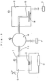
- Fig. 2 is a schematic view showing a fundamental composition of a manufacturing device for use in Embodiments 4 and 5.
- Fig. 3 is a schematic view showing the general arrangement of a manufacturing device for use in Embodiments 6 and 7.
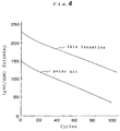
- Fig. 4 is a view showing results of charge/discharge cycle test for electrodes of this invention and prior art in the Embodiment 6.
- Fig. 5 is a view showing a result of charge/discharge cycle test for an electrode obtained from Embodiment 7.
- This embodiment relates to a manufacturing method for a cathode from manganese dioxide.
- Fig. 1 is a schematic view of a manufacturing device.
- 1 is an evaporation chamber
- 2 is a crucible
- 3 is a heater
- 4 is a differential pumping chamber
- 5 is a nozzle at the tip of a delivery pipe 5a
- 6 is a spray chamber
- 7 is a vacuum pump
- 8 is a substrate made of stainless foil
- 9 is a lead-in pipe for supply gas.
- Inert gas (helium in this embodiment) is used for the supply gas.
- the opening of the nozzle 5 is 0.8mm x 10mm.
- a high frequency induction heater is used for the heater 3.
- manganese dioxide put in the crucible 2 was converted into vapor by being heated, molten and vaporized in the heater 3 under an atmosphere of helium gas to form ultra fine particles from the manganese dioxide composed of the vapor condensing to sizes of 0.1 x 10 -6 m to 0.3 x 10 -6 m (0.1 to 0.3 microns).
- the ultra fine particles from the manganese dioxide were carried by helium gas flow to the nozzle 5 through the delivery pipe 5a, and then blown from the nozzle 5 onto a surface of the substrate 8 installed in the spray chamber 6.
- a film from the manganese dioxide having a width of 10 mm, a length of 10 mm and a thickness of 10 ⁇ m i.e. a cathode composed of particles formed from dioxide, was formed on the surface of substrate 8.
- This film is one obtained by injecting and depositing the ultra fine particles formed from manganese dioxide, i.e. by means of the gas deposition method, and so that this film is rigid and cannot be obtained by an ordinary sheeting method. Further, the above-mentioned method is of a dry type and pure so that it does not require a binder.
- the cathode composed of an ultra thin film having an uniform thickness can be produced with good productivity.
- the electrode generally has a better volume energy efficiency with a decrease in porosity (an increase in charging efficiency).
- the material of electrode should be in proper contact with the electrolyte so as to provide efficient occlusion and emission of ion in the electrolyte. Therefore, the electrode should be formed so as to include a proper porosity. According to the above-mentioned method, an electrode having a desired porosity can be produced by continuously adjusting the blowing velocity of the active material onto the substrate 8.
- This embodiment relates to a manufacturing method for an anode comprising lithium.
- lithium was put in the crucible 2 in place of the manganese dioxide and a resistance heater was used in place of the heater 3, and the same operation as in Embodiment 1 was carried out under the same conditions.
- a film of lithium having a width of 10 mm, a length of 10 mm and a thickness of 10 ⁇ m i.e. an anode composed of lithium was formed on the surface of the substrate 8.
- This film is one obtained by injecting and depositing the ultra fine particles of lithium, i.e. by means of the gas deposition method, and could not be obtained by an ordinary melting, solidifying, or rolling method.
- the anode of lithium composed of an ultra thin film having an uniform thickness can be produced, with good productivity. Further, an electrode having a desired porosity can be produced by continuously adjusting the blowing velocity of the active material.
- differential pumping chamber 4 There may be a case where the differential pumping chamber 4 is not used. Moreover, when a lithium alloy is used in place of lithium, an anode comprising lithium alloy can be formed.
- This embodiment relates to a manufacturing method for a cathode comprising manganese dioxide, different from that described in Embodiment 1.
- the ultra fine particles of manganese dioxide were carried by mixed gas flow to the nozzle 5 through the delivery pipe 5a, and blown from the nozzle 5 onto a surface of the substrate 8 installed in the spray chamber 6.
- a coating film having a width of 10 mm, a length of 10 mm and a thickness of 0.01 mm (10 microns) was formed on the surface of the substrate 8. This coating film was identified as MnO 2 when tested by the X-ray diffraction method.
- a film of manganese dioxide i.e. the anode composed of manganese dioxide was formed on the surface of the substrate 8.
- This film is one obtained by injecting and depositing the ultra fine particles of manganese dioxide, i.e. by means of the gas deposition method. It is rigid and cannot be obtained by an ordinary chemical synthesizing method or sheeting method. Further, the above-mentioned method is of a dry type and pure so that it does not require a binder.
- the cathode of manganese dioxide composed of an ultra thin film having an uniform thickness can be produced with good productivity. Further, an electrode having a desired porosity can be produced by continuously adjusting the blowing velocity of the active material.
- a cathode comprising active material which is an oxide of the above material can be formed.
- This embodiment relates to a manufacturing method for an electrode comprising active material of multi-component system.
- Fig. 2 is a schematic view of a manufacturing device.
- 11 is a spray chamber
- 12, 13, 14 & 15 are evaporation chambers
- 16, 17, 18 & 19 are crucibles
- 20, 21, 22 & 23 are bombs for feeding inert gas to the evaporation chambers 12, 13, 14 & 15
- 24 is a bomb for feeding oxygen gas to the spray chamber 11
- 25 is a substrate composed of stainless foil
- 26 is a heater
- 27 is a vacuum pump
- 28 is a nozzle having a tip end opening size of 0.8 mm x 10 mm
- 29 is a lead-in pipe
- 30 is a high frequency induction heater.
- Argon gas is used for the above inert gas in this instance.
- lithium, vanadium, cobalt & vanadium put in the respective crucibles 16, 17, 18 & 19 were vaporized by being heated and molten in the high frequency induction heater 30 and then cooled under an atmosphere of argon gas so as to form ultra fine particles of respective metals.
- the ultra fine particles of metals formed in respective evaporation chambers 12, 13, 14 & 15 were carried by argon gas flow to be mixed while being passed through the lead-in pipe 29, and then blown from the nozzle 28 onto a surface of the substrate 25 installed in the spray chamber 11. Thereby, a film having a width of 10 mm, a length of 10 mm and a thickness of 10 ⁇ m was formed on the surface of the substrate 25.
- the film on the surface of the substrate 25 was heated by the heater 26 while leading oxygen gas from the bomb 24 into the spray chamber 11 so that the oxygen was made to react with the film at 700°C.
- This film after reaction was identified as LiV 2 CoO 8 when tested by the X-ray diffraction method and the elemental analysis method. Namely, an electrode comprising active materials of multi-component system was formed on the surface of the substrate 25.
- the above-mentioned method is of a dry type and pure so that it does not require a binder.
- the electrode can be produced with good productivity, which is composed of the active material of multi-component system having an excellent property and composed of an ultra thin film having a high density, an uniform composition and an uniform thickness. Further, an electrode having a voluntary porosity can be produced by continuously adjusting the blowing velocity of the active material.
- the vaporized metal is not limited to the foregoing lithium, vanadium and cobalt but may be selected appropriately from manganese, cobalt, nickel, zinc, tin, lead, lithium, molybdenum, vanadium, chrome, iron, ruthenium, osmium, tungsten, copper and silver.
- an electrode comprising various polyatomic active materials may be formed.
- This embodiment relates to a manufacturing method for a cathode of lithium battery.
- Fig. 3 is the schematic view of a manufacturing device.
- 50 is a spray chamber
- 60 is an aerosol container
- 70 is an evaporation chamber
- 71 is a lead-in pipe for leading in carrier gas
- 72 is a delivery pipe
- 73 is a pump
- 74 is a crucible
- 75 is a heater
- 76 is a heater power supply
- 61 is a lead-in pipe for leading in carrier gas
- 62 is a delivery pipe
- 51 is a first nozzle at the tip of the delivery pipe 62
- 52 is a second nozzle at the tip of the delivery pipe 72
- 53 is a gas lead -in pipe
- 54 is a substrate.
- Tip end sizes of both nozzles 51 & 52 are 0.8 mm x 10 mm.
- the two nozzles 51 & 52 are so installed as to blow gas onto the same spot of the substrate.
- Ultra fine particles of lithium composed of the vapor condensing to sizes of 0.1 to 0.3 ⁇ m were carried by helium gas, led from the lead-in pipe 71, through the delivery pipe 72 to the second nozzle 52 and blown onto the surface of the substrate 54.
- the quantity of ultra fine particles blown in this instance from the two nozzles 51 & 52 was regulated by adjusting pressures in the aerosol container 60 and the evaporation chamber 70.
- a rigid deposit 55 having a width of 10 mm, a length of 10 mm and a thickness of 100 ⁇ m was formed on the surface of the substrate 54.
- This deposit 55 was taken out into an atmosphere of inert gas and its electrode characteristics examined. Observation was also made using a scanning electron microscope.
- the obtained deposit 55 was also immersed in a solution (liquid electrolyte) in which lithium perchlorate was dissolved in a solvent made by mixing propylene carbonate with dimethoxyethane, in the same volume, for one hour. Then it was taken out and rinsed with pure dimethoxyethane, and its chemical composition analysis was carried out. The analysis proved that its composition could be expressed by a chemical formula Li 1.9 Mn 2 O 4 .
- a simple electro-chemical cell (abbreviated to "invention” hereunder) was assembled by using a liquid electrolyte in which lithium perchlorate was solved in the solvent of propylene carbonate mixed with dimethoxyethane in the same volume.
- the invention developed a voltage of 1.92 V.
- a simple electro-chemical cell (abbreviated to "prior art” hereunder) was assembled for comparison, by using an electrode which had been obtained by previously electro-chemically deoxidizing a sheeted material utilizing polytetrafluoro-ethylene as a binder up to Li 2 Mn 2 O 4 with lithium, as the cathode and by using the anode and electrolyte identical with the invention.
- Charge/discharge cycle test was conducted on the invention and the prior art with a current density of 0.1 mA/cm 2 per area of cathode. Results are shown in Fig. 4.
- Charge/discharge end voltage was set to 3.5 V maximum and 2.0 V minimum.
- a discharging capacity per volume measured from a first cycle's discharging capacity was 230 mAh/cm 3 for this invention and 150 mAh/cm 3 for the prior art.
- the electrode of this invention is one having a very high volume energy density.
- the anode of this embodiment has a composition and structure corresponding to the state of discharging end, which can not be obtained by an ordinary sheeting method, and requires no binder.
- the method is of the dry type and pure.
- the ultra thin plate for lithium battery having an excellent volume efficiency and a uniform thickness can be obtained with good productivity, and the assembly process of battery can be simplified. Further, an electrode having a desired porosity can be produced by continuously adjusting the blowing velocity of the active material.
- This embodiment relates to a manufacturing method for an anode for lithium battery.
- pitch-related carbon material in a form of ultra fine particles having sizes of 0.1 to 0.3 ⁇ m was put in the aerosol container 60, commercial lithium metal was put in the crucible 74, and the same operations as in Embodiment 6 were carried out.
- black or gray deposit i.e. an electrode comprising carbon-lithium having a width of 10 mm, a length of 10 mm and a thickness of 100 ⁇ m was formed on the surface of the substrate 54.
- This deposit is rigid because it was obtained by the gas deposition method.
- the electrode thus formed was taken out in an atmosphere of inert gas and its weight was measured.
- a formed electrode cut out to a size of 1 cm 2 was used as a working electrode, lithium metal was used as a counter electrode, lithium metal was also used as a reference electrode, and a solution in which lithium arsenate hexafluoride was dissolved in a mixture of propylenecarbonate and ethylene-carbonate was used as an electrolyte; so that an electro-chemical cell was assembled.
- the performance of the single battery was evaluated by this cell.
- a potential difference between the reference electrode and the active electrode was 0.003 V.
- a current was made to flow between the working electrode and the counter electrode (i.e. de-doping) while monitoring an electric potential of the working electrode by the reference electrode.
- Measurement of electrode thickness was made by observing its section using an electron microscope. A capacity of the first was 346 mAh/cm 3 . Since the capacity for the sheeting method of prior art is 270 to 280 mAh/cm 3 , it can be understood that the capacity per volume of the electrode produced by the foregoing method is improved by a large margin.
- a volume energy efficiency of the carbon-lithium compound electrode generally has a better volume energy efficiency with a decrease in porosity (an increase in charging density).
- porosity an increase in charging density
- the material of electrode should properly be in contact with the electrolyte so as to provide efficient occlusion and emission of ions in the electrolyte.
- porosity is too small, an electrode having a good electro-chemical efficiency cannot be obtained because the contact area with the electrolyte is limited. Consequently, there exists an optimum value for the porosity.
- the carbon electrode of prior art has generally been manufactured by the method sheeting the ultra fine particles of carbon using the binder, and its porosity has been 40 to 60%.
- the porosity can be controlled at will. That is, the velocity at which the ultra fine particles are blown onto the surface of the substrate 54 can be adjusted continuously by regulating the pressure difference between the evaporation chamber 70 and the spray chamber 50, and the porosity can thus be reduced to approx. 0%.
- the foregoing method is of a dry type and pure because it does not require the use of binder. Further, the ultra thin lithium battery having an excellent volume efficiency and an uniform thickness can be manufactured by the foregoing method with good productivity. Moreover, its assembly process can also be simplified.
- This embodiment relates to a manufacturing method for an electrode (cathode)-electrolyte composite.
- a film of manganese dioxide i.e. a cathode composed of manganese dioxide having a width of 10 mm, a length of 10 mm and a thickness of 10 ⁇ m was formed on the surface of the film 8.
- the film is one formed through deposition of injected ultra fine particles of manganese dioxide i.e. obtained by means of the gas deposition method, so that this film is rigid and can not be obtained by the ordinary sheeting method. Further, the above-mentioned method does not require a binder so that it is of a dry type and pure.
- the electrode-electrolyte composite can also be produced with good productivity, which has an excellent adhesion of the electrode with the solid electrolyte. Further, the electrode of ultra thin type with uniform thickness can be produced. Moreover, an electrode having a voluntary porosity can be produced by continuously adjusting the blowing velocity of the active material.
Landscapes
- Chemical & Material Sciences (AREA)
- Chemical Kinetics & Catalysis (AREA)
- General Chemical & Material Sciences (AREA)
- Electrochemistry (AREA)
- Engineering & Computer Science (AREA)
- Manufacturing & Machinery (AREA)
- Inorganic Chemistry (AREA)
- Materials Engineering (AREA)
- Dispersion Chemistry (AREA)
- Physics & Mathematics (AREA)
- General Physics & Mathematics (AREA)
- Condensed Matter Physics & Semiconductors (AREA)
- Battery Electrode And Active Subsutance (AREA)
- Secondary Cells (AREA)
Description
- This invention relates to a manufacturing method for an electrode in a film-type battery.
- A conventional cathode for a film-type battery is manufactured as a sheet-shaped thin film by mixing conductor, binder and positive active material. In this method, however, a thickness of the thin film has been dependent on the particle size and loading rate of the positive active material. It has been hard to obtain a sub-micron (< 1 µm) particule size and difficult to increase the charging rate, so that it has been not easy to obtain a thin film having a thickness of 10 µm or less.
- Methods of utilizing lithium or lithium alloy for a anode have been proposed variously, however, it has been difficult to obtain a thin film of uniform thickness composed of lithium. In a method for manufacturing a thin film by extruding lithium from a nozzle, for example, a lower limit of thickness of the thin film has been 0.03 mm. At lower thicknesses uniformity is lost.
- In methods for obtaining thin film by rolling, a lower limit of thickness of the thin film has been 0.02 to 0.03 mm.
- Carbon electrodes have been manufactured as a sheet-shaped thin film by mixing a carbon material and a binder. However the thickness of the sheet is dependent on the loading rate of carbon material, and it has been difficult to obtain a thin film electrode having a thickness of 10 µm or less.
- As described above, in the conventional method it has been difficult to obtain an anode or a cathode composed of an ultra thin film having a uniform thickness of 10 µm or less, for example, with good productivity.
- Methods for manufacturing the thin film electrode by means of a vacuum coating method or sputtering method have been proposed, for example in WO-A-85/03460. In these methods, however, the film forming rate is small so that the method is suitable for forming a film having a thickness of less than several tens of nanometres but not suitable for a thickness larger than that. On the other hand, in order to improve the film forming rate, a method wherein ultra fine particles of metal are directly carried in gas flow and deposited on a substrate at a high velocity has been proposed in JP-A-1/265450. However, this method is a discontinuous and inefficient film forming process. Obtaining active materials of multi-component systems by this method has provided bad productivity because of expense in obtaining fine particles of various metals and difficulty in mixing them uniformly. Moreover, it has been impossible to obtain active materials of multi-component system having excellent properties by this method.
- In recent years, the study and development of secondary lithium batteries are flourishing. Using metallic lithium for the anode in a secondary lithium battery will cause trouble from the standpoint of deterioration of performance and safety, accompanied by dendrite formation at time of charging. In order to overcome this problem, it has been proposed to use carbon, capable of occlusion and emission of lithium as the anode material. In a lithium battery utilizing a normal lithium intercalation active material as the cathode and a carbon electrode as the anode, it is necessary to dope the lithium into the carbon electrode previously. For this reason, the carbon electrode has required a troublesome "doping process" before assembly. In order to eliminate the preliminary doping process for carbon electrodes, it is proposed that an active material having a structure reduced by lithium is synthesized to be used as the cathode active material. The manufacturing process can be simplified by this method. For example, LiMn2O4 which is a spinel-related lithium manganese oxide compound, can be used as the cathode active material for a secondary lithium battery and can be synthesized easily. It is well known that the state of the cathode active material at the end of charging will change up to Li2Mn2O4, when a battery is assembled using the above material with a lithium-related anode material and discharged. Accordingly, if the spinel-related manganese compound expressed by the chemical formula of Li2Mn2O4 can be synthesized, a secondary lithium battery can be composed by combining that compound and an undoped carbon electrode. However, it requires further various studies to chemically synthesize the lithium reductant Li2Mn2O4, and a process of "previous discharging" becomes necessary in order to synthesize the reductant electro-chemically. To eliminate the preliminary doping process, for carbon electrodes, it can also be proposed to form a carbon electrode in which lithium has been doped previously.
- On the other hand, it is desired to use a solid electrolyte, especially a solid polymer electrolyte, as an ionic conductive material in a film-type battery. This is because the solid electrolyte has advantages of ease in manufacture, freeness from liquid leakage, and capability of manufacturing cells having desired shapes. When using a solid electrolyte, however, means for maintaining a good adhesion state between the electrode and electrolyte, e.g. pressure welding of the two, will be required. In the case of a film-type battery, especially a flexible battery, it is difficult to apply pressure from outside or inside as encountered in a prismatic battery or a spiral cylindrical battery, so that serious problems such as adhesion failure between the electrode and electrolyte have occurred.
- In addition to good adhesion between the electrode and electrolyte, the following points are required: [1] An effective contacting area between an electrode material and a packaging material which forms a current collector must be maintained in a good state. [2] An organic electrolyte battery, such as a lithium battery, must be protected from influence of water content because a composite composed of the electrode and the electrolyte reacts with water to form an undesirable material for batteries.
- Further, the following literature references are prior art: [1] "Surface Technology" 8, 335, 1987, M. Oda, 'Formation and Application of Ultra Fine particles by In-Gas Evaporation Method', [2] "Applied Physics" 54, 687, 1985, C. Hayashi, 'Gas Deposition of Ultra Fine Particles', [3] "Japanese Journal of Applied Physics" 23, L910, 1984, S. Kashu, E. Fuchita, T. Manabe, C. Hayashi, 'Deposition of Ultra Fine Particles Using a Gas Jet'.
- The general aim herein is to provide a new and useful method for making electrodes, in particular suitable for thin-film batteries.
- Preferred aims include:
- good productivity for an ultra thin electrode film having a uniform thickness of e.g. 10 µm or less;
- good productivity for an electrode film composed of an active material of a multi-component system which has a uniform composition of high density, is ultra thin and of uniform thickness;
- an ultra thin electrode for a lithium battery having good productivity, excellent volume efficiency and uniform thickness;
- an ultra-thin electrode-electrolyte composite, with good productivity, in which adhesion between the electrode and the electrolyte is excellent and the electrode is of an ultra thin type having a uniform thickness;
- an electrode-electrolyte composite as described above, which includes a sufficient perforated contacting area with a packaging material and is free from the bad influence of atmospheric water.
- In one aspect the invention provides a method making a film-type battery including an electrode which is a thin film of active material, characterised in that the electrode is formed by a process comprising the steps of
- forming ultra fine particles of a material which is the active material or is subsequently converted to it, the ultra fine particles being formed in gas by a process comprising evaporation of the material and subsequent condensation to form the ultra fine particles;
- carrying the ultra fine particles in gas flow and blowing them onto the surface of a substrate to form the desired thin film thereon.
- In another aspect the invention provides a method in which an electrode is made by a process as described and used as an electrode.
- Various options and preferences are set out in the subclaims.
- The ultra fine particles may be of plural metals; a thin film thereof may be made to react with oxygen while being heated to form the active material as a multi-component system. Alternatively, the ultra fine particles may be made to react with oxygen mixed in the gas and then blown onto the surface of the substrate.
- The ultra fine particles may be of metal compound and of lithium to be carried by gas flow and blown simultaneously onto the same substrate surface and deposited on it, so that a cathode for a lithium battery is formed on the surface of substrate. Furthermore, such a deposit may be dipped in a liquid electrolyte to react electro-chemically, so that a cathode for lithium battery is formed on the surface of substrate. The ultra fine particles may be of carbon material and of lithium to be carried by the gas flow and blown simultaneously onto the same substrate surface and deposited on it, so that a cathode for a lithium battery composed of carbon-lithium compound is formed.
- The substrate may be a solid electrolyte film, e.g. polymeric, so that an electrode composed of a thin film of active material is formed on the film surface, giving an electrode-electrolyte composite. A positive active material may be blown onto one surface of the film and a negative active material onto the other surface.
- Ultra fine particles of metal of a type different from the active material and formed by the evaporation-condensation method may further be carried by gas to be blown onto a surface of the active material film so that a metal film is formed on the surface of electrode.
- Fig. 1 is a schematic view showing the general arrangement of a manufacturing device for use in
Embodiments Embodiments Embodiments Embodiment 6. Fig. 5 is a view showing a result of charge/discharge cycle test for an electrode obtained fromEmbodiment 7. - This embodiment relates to a manufacturing method for a cathode from manganese dioxide.
- Fig. 1 is a schematic view of a manufacturing device. In this figure, 1 is an evaporation chamber, 2 is a crucible, 3 is a heater, 4 is a differential pumping chamber, 5 is a nozzle at the tip of a
delivery pipe nozzle 5 is 0.8mm x 10mm. A high frequency induction heater is used for theheater 3. - First, in the
evaporation chamber 1, manganese dioxide put in thecrucible 2 was converted into vapor by being heated, molten and vaporized in theheater 3 under an atmosphere of helium gas to form ultra fine particles from the manganese dioxide composed of the vapor condensing to sizes of 0.1 x 10⁻⁶m to 0.3 x 10⁻⁶m (0.1 to 0.3 microns). After setting a pressure of helium gas in the evaporation chamber 133.32Pa to 13332Pa (1 to 100 torr) and a pressure in the spray chamber 799.9Pa to 15.98Pa (6 to 0.12 torr), the ultra fine particles from the manganese dioxide were carried by helium gas flow to thenozzle 5 through thedelivery pipe 5a, and then blown from thenozzle 5 onto a surface of thesubstrate 8 installed in thespray chamber 6. Thereby, a film from the manganese dioxide having a width of 10 mm, a length of 10 mm and a thickness of 10 µm i.e. a cathode composed of particles formed from dioxide, was formed on the surface ofsubstrate 8. This film is one obtained by injecting and depositing the ultra fine particles formed from manganese dioxide, i.e. by means of the gas deposition method, and so that this film is rigid and cannot be obtained by an ordinary sheeting method. Further, the above-mentioned method is of a dry type and pure so that it does not require a binder. - According to the above-mentioned method as described above,the cathode composed of an ultra thin film having an uniform thickness can be produced with good productivity.
- Incidentally, it appears that the electrode generally has a better volume energy efficiency with a decrease in porosity (an increase in charging efficiency). In order to have it function as an electrode, however, the material of electrode should be in proper contact with the electrolyte so as to provide efficient occlusion and emission of ion in the electrolyte. Therefore, the electrode should be formed so as to include a proper porosity. According to the above-mentioned method, an electrode having a desired porosity can be produced by continuously adjusting the blowing velocity of the active material onto the
substrate 8. - There may be a case where the
differential pumping chamber 4 is not used. - This embodiment relates to a manufacturing method for an anode comprising lithium.
- In the device shown in Fig. 1, lithium was put in the
crucible 2 in place of the manganese dioxide and a resistance heater was used in place of theheater 3, and the same operation as inEmbodiment 1 was carried out under the same conditions. Thereby, a film of lithium having a width of 10 mm, a length of 10 mm and a thickness of 10 µm i.e. an anode composed of lithium was formed on the surface of thesubstrate 8. This film is one obtained by injecting and depositing the ultra fine particles of lithium, i.e. by means of the gas deposition method, and could not be obtained by an ordinary melting, solidifying, or rolling method. - According to the above-mentioned method as described above, the anode of lithium composed of an ultra thin film having an uniform thickness can be produced, with good productivity. Further, an electrode having a desired porosity can be produced by continuously adjusting the blowing velocity of the active material.
- There may be a case where the
differential pumping chamber 4 is not used. Moreover, when a lithium alloy is used in place of lithium, an anode comprising lithium alloy can be formed. - This embodiment relates to a manufacturing method for a cathode comprising manganese dioxide, different from that described in
Embodiment 1. - Referring to the device shown in Fig. 1; in the
evaporation chamber 1, manganese put in thecrucible 2 was converted into vapor by being heated, molten and vaporized in the highfrequency induction heater 3 under an atmosphere of mixed gas of helium and oxygen so as to form ultra fine particles of manganese by the vapor condensing to sizes of 0.1 to 0.3 µm. The ultra fine particles of manganese formed as above react with oxygen to become ultra fine particles of manganese dioxide. After setting a pressure of the mixed gas in the evaporation chamber 133.32Pa to 13332Pa (1 to 100 torr) and a pressure in the spray chamber 799.9Pa to 15.98Pa (6 to 0.12 torr), the ultra fine particles of manganese dioxide were carried by mixed gas flow to thenozzle 5 through thedelivery pipe 5a, and blown from thenozzle 5 onto a surface of thesubstrate 8 installed in thespray chamber 6. Thereby, a coating film having a width of 10 mm, a length of 10 mm and a thickness of 0.01 mm (10 microns) was formed on the surface of thesubstrate 8. This coating film was identified as MnO2 when tested by the X-ray diffraction method. Namely, a film of manganese dioxide i.e. the anode composed of manganese dioxide was formed on the surface of thesubstrate 8. This film is one obtained by injecting and depositing the ultra fine particles of manganese dioxide, i.e. by means of the gas deposition method. It is rigid and cannot be obtained by an ordinary chemical synthesizing method or sheeting method. Further, the above-mentioned method is of a dry type and pure so that it does not require a binder. - According to the above-mentioned method the cathode of manganese dioxide composed of an ultra thin film having an uniform thickness can be produced with good productivity. Further, an electrode having a desired porosity can be produced by continuously adjusting the blowing velocity of the active material.
- When vanadium, molybdenum, titanium, cobalt, or chromium is used in place of manganese, a cathode comprising active material which is an oxide of the above material can be formed.
- This embodiment relates to a manufacturing method for an electrode comprising active material of multi-component system.
- Fig. 2 is a schematic view of a manufacturing device. In the figure; 11 is a spray chamber; 12, 13, 14 & 15 are evaporation chambers; 16, 17, 18 & 19 are crucibles; 20, 21, 22 & 23 are bombs for feeding inert gas to the evaporation chambers 12, 13, 14 & 15; 24 is a bomb for feeding oxygen gas to the
spray chamber 11; 25 is a substrate composed of stainless foil; 26 is a heater; 27 is a vacuum pump; 28 is a nozzle having a tip end opening size of 0.8 mm x 10 mm; 29 is a lead-in pipe; and 30 is a high frequency induction heater. Argon gas is used for the above inert gas in this instance. - In the evaporation chambers 12, 13, 14 & 15; lithium, vanadium, cobalt & vanadium put in the
respective crucibles 16, 17, 18 & 19 were vaporized by being heated and molten in the highfrequency induction heater 30 and then cooled under an atmosphere of argon gas so as to form ultra fine particles of respective metals. After setting pressures of the argon gas in the evaporation chambers 12, 13, 14 & 15 to 13332Pa (100 torr) and a pressure in thespray chamber 11 to 15.98Pa (0.12 torr), the ultra fine particles of metals formed in respective evaporation chambers 12, 13, 14 & 15 were carried by argon gas flow to be mixed while being passed through the lead-inpipe 29, and then blown from thenozzle 28 onto a surface of the substrate 25 installed in thespray chamber 11. Thereby, a film having a width of 10 mm, a length of 10 mm and a thickness of 10 µm was formed on the surface of the substrate 25. The film on the surface of the substrate 25 was heated by theheater 26 while leading oxygen gas from thebomb 24 into thespray chamber 11 so that the oxygen was made to react with the film at 700°C. This film after reaction was identified as LiV2CoO8 when tested by the X-ray diffraction method and the elemental analysis method. Namely, an electrode comprising active materials of multi-component system was formed on the surface of the substrate 25. The above-mentioned method is of a dry type and pure so that it does not require a binder. - According to the above-mentioned method as described above, the electrode can be produced with good productivity, which is composed of the active material of multi-component system having an excellent property and composed of an ultra thin film having a high density, an uniform composition and an uniform thickness. Further, an electrode having a voluntary porosity can be produced by continuously adjusting the blowing velocity of the active material.
- Incidentally, the vaporized metal is not limited to the foregoing lithium, vanadium and cobalt but may be selected appropriately from manganese, cobalt, nickel, zinc, tin, lead, lithium, molybdenum, vanadium, chrome, iron, ruthenium, osmium, tungsten, copper and silver. Thereby, an electrode comprising various polyatomic active materials may be formed.
- Operations similar to the
Embodiment 4 were carried out except that oxygen gas was mixed in thespray chamber 11 before the ultra fine particles of metals were blown onto the surface of the substrate 25. In this method, ultra fine particles of metals of some kinds become oxides before being blown onto the surface of the substrate. The above-mentioned method is also of a dry type and pure so that it does not require the binder. The electrode can also be produced with good productivity, which is composed of active material of multi-component system having an excellent property and composed of an ultra thin film having a high density, an uniform composition and an uniform thickness. Further, an electrode having a desired porosity can be produced by continuously adjusting the blowing velocity of the active material. - This embodiment relates to a manufacturing method for a cathode of lithium battery.
- Fig. 3 is the schematic view of a manufacturing device. In the figure, 50 is a spray chamber, 60 is an aerosol container, 70 is an evaporation chamber, 71 is a lead-in pipe for leading in carrier gas, 72 is a delivery pipe, 73 is a pump, 74 is a crucible, 75 is a heater, 76 is a heater power supply, 61 is a lead-in pipe for leading in carrier gas, 62 is a delivery pipe, 51 is a first nozzle at the tip of the
delivery pipe delivery pipe - First, 10 weight parts of spinel-related lithium manganese dioxide compound including ultra fine particles having a size of 0.1 to 0.3 µm were mixed with 1 weight part of acetylene black uniformly, and then thrown into the
aerosol container 60. On the other hand, commercial metallic lithium was put in the crucible 74 installed in theevaporation chamber 70. Secondly, helium gas was led from the lead-inpipe 61 into theaerosol container 60, ultra fine particles 63 were carried by helium gas to be led through thedelivery pipe 62 to the first nozzle 51, and then blown onto the surface of thesubstrate 54. At the same time,lithium 77 in the crucible 74 was heated, molten and vaporized by the heater 75. Ultra fine particles of lithium composed of the vapor condensing to sizes of 0.1 to 0.3 µm were carried by helium gas, led from the lead-inpipe 71, through thedelivery pipe 72 to thesecond nozzle 52 and blown onto the surface of thesubstrate 54. The quantity of ultra fine particles blown in this instance from the two nozzles 51 & 52 was regulated by adjusting pressures in theaerosol container 60 and theevaporation chamber 70. Thereby, arigid deposit 55 having a width of 10 mm, a length of 10 mm and a thickness of 100 µm was formed on the surface of thesubstrate 54. Thisdeposit 55 was taken out into an atmosphere of inert gas and its electrode characteristics examined. Observation was also made using a scanning electron microscope. - The obtained
deposit 55 was also immersed in a solution (liquid electrolyte) in which lithium perchlorate was dissolved in a solvent made by mixing propylene carbonate with dimethoxyethane, in the same volume, for one hour. Then it was taken out and rinsed with pure dimethoxyethane, and its chemical composition analysis was carried out. The analysis proved that its composition could be expressed by a chemical formula Li1.9Mn2O4. - Using the
deposit 55 thus obtained as the cathode and metal lithium as the anode, a simple electro-chemical cell (abbreviated to "invention" hereunder) was assembled by using a liquid electrolyte in which lithium perchlorate was solved in the solvent of propylene carbonate mixed with dimethoxyethane in the same volume. The invention developed a voltage of 1.92 V. On the other hand, a simple electro-chemical cell (abbreviated to "prior art" hereunder) was assembled for comparison, by using an electrode which had been obtained by previously electro-chemically deoxidizing a sheeted material utilizing polytetrafluoro-ethylene as a binder up to Li2Mn2O4 with lithium, as the cathode and by using the anode and electrolyte identical with the invention. Charge/discharge cycle test was conducted on the invention and the prior art with a current density of 0.1 mA/cm2 per area of cathode. Results are shown in Fig. 4. Charge/discharge end voltage was set to 3.5 V maximum and 2.0 V minimum. A discharging capacity per volume measured from a first cycle's discharging capacity was 230 mAh/cm3 for this invention and 150 mAh/cm3 for the prior art. As seen from this value, the electrode of this invention is one having a very high volume energy density. - The anode of this embodiment has a composition and structure corresponding to the state of discharging end, which can not be obtained by an ordinary sheeting method, and requires no binder. The method is of the dry type and pure. When a carbon material capable of doping with lithium is used as the anode, the battery assembly process can be simplified because it is not necessary to previously dope the lithium into the anode.
- According to the foregoing manufacturing method as described above, the ultra thin plate for lithium battery having an excellent volume efficiency and a uniform thickness can be obtained with good productivity, and the assembly process of battery can be simplified. Further, an electrode having a desired porosity can be produced by continuously adjusting the blowing velocity of the active material.
- The same effect as in the above embodiment will be accomplished even when a vanadium compound or a manganese compound is used in place of the spinel-related lithium manganese dioxide compound.
- This embodiment relates to a manufacturing method for an anode for lithium battery.
- In Fig. 3, pitch-related carbon material in a form of ultra fine particles having sizes of 0.1 to 0.3 µm was put in the
aerosol container 60, commercial lithium metal was put in the crucible 74, and the same operations as inEmbodiment 6 were carried out. Thereby, black or gray deposit i.e. an electrode comprising carbon-lithium having a width of 10 mm, a length of 10 mm and a thickness of 100 µm was formed on the surface of thesubstrate 54. This deposit is rigid because it was obtained by the gas deposition method. - The electrode thus formed was taken out in an atmosphere of inert gas and its weight was measured.
- Part of it was subjected to chemical analysis, and the remainder was utilized for investigation of electrode characteristics. Whether or not a carbon-lithium compound electrode desirable for the battery electrode has been obtained, can be judged firstly by a voltage which is developed by the electrode in an organic electrolyte, and secondly by a quantity of electricity which can take out or take in (de-doping and doping) lithium electro-chemically from or to that electrode in the organic electrolyte. A formed electrode cut out to a size of 1 cm2 was used as a working electrode, lithium metal was used as a counter electrode, lithium metal was also used as a reference electrode, and a solution in which lithium arsenate hexafluoride was dissolved in a mixture of propylenecarbonate and ethylene-carbonate was used as an electrolyte; so that an electro-chemical cell was assembled. The performance of the single battery was evaluated by this cell. A potential difference between the reference electrode and the active electrode was 0.003 V. First, a current was made to flow between the working electrode and the counter electrode (i.e. de-doping) while monitoring an electric potential of the working electrode by the reference electrode. A quantity of electricity flowing before the electric potential of the reference electrode became 1.000 V was measured, so the capacity of the electrode was measured. The result was 244 mAh/g. Then, a cycle test repeating doping/dedoping was carried out. The doping was done by connecting the working electrode and counter electrode using a lead wire and allowing the working electrode to stand until its electric potential became 0 V. The de-doping capacity was measured in the same manner as above and its change accompanied by cycle number was measured. The result as shown in Fig. 4 was obtained. A capacity of 226 mAh/g is maintained at 80 cycles. As an electrode for a lithium battery, this result is not inferior to an electrode produced by the sheeting method of the prior art. The electrode capacity was then converted into a value per volume and evaluated. Measurement of electrode thickness was made by observing its section using an electron microscope. A capacity of the first was 346 mAh/cm3. Since the capacity for the sheeting method of prior art is 270 to 280 mAh/cm3, it can be understood that the capacity per volume of the electrode produced by the foregoing method is improved by a large margin.
- A volume energy efficiency of the carbon-lithium compound electrode generally has a better volume energy efficiency with a decrease in porosity (an increase in charging density). In order to have it function as the electrode, however, it is required that the material of electrode should properly be in contact with the electrolyte so as to provide efficient occlusion and emission of ions in the electrolyte. When the porosity is too small, an electrode having a good electro-chemical efficiency cannot be obtained because the contact area with the electrolyte is limited. Consequently, there exists an optimum value for the porosity. The carbon electrode of prior art has generally been manufactured by the method sheeting the ultra fine particles of carbon using the binder, and its porosity has been 40 to 60%. According to the above-mentioned method, however, the porosity can be controlled at will. That is, the velocity at which the ultra fine particles are blown onto the surface of the
substrate 54 can be adjusted continuously by regulating the pressure difference between theevaporation chamber 70 and thespray chamber 50, and the porosity can thus be reduced to approx. 0%. - As described above, the foregoing method is of a dry type and pure because it does not require the use of binder. Further, the ultra thin lithium battery having an excellent volume efficiency and an uniform thickness can be manufactured by the foregoing method with good productivity. Moreover, its assembly process can also be simplified.
- This embodiment relates to a manufacturing method for an electrode (cathode)-electrolyte composite.
- In the device shown in Fig. 1 manganese was put in the
crucible 2, and heated, molten and vapourised by theheater 3 in theevaporation chamber 1 under an atmosphere of mixed gas of helium and oxygen. Ultra fine particles of manganese having sizes of 0.1 to 0.3 mm, which were formed in theevaporation chamber 1, reacted with oxygen gas to become ultra fine particles of manganese dioxide, and were then blown onto the surface of thesubstrate 8, a solidpolymer electrolyte film 50 µm thick made by cross-linking tri-functional polyether copolymer of ethylene oxide with propylene oxide (MW 3000), in which 10 wt% lithium perchlorate is dissolved, using hexamethylene diisocyanate as cross-linking agent. A film of manganese dioxide, i.e. a cathode composed of manganese dioxide having a width of 10 mm, a length of 10 mm and a thickness of 10 µm was formed on the surface of thefilm 8. The film is one formed through deposition of injected ultra fine particles of manganese dioxide i.e. obtained by means of the gas deposition method, so that this film is rigid and can not be obtained by the ordinary sheeting method. Further, the above-mentioned method does not require a binder so that it is of a dry type and pure. - According to the above-mentioned method as described above, the electrode-electrolyte composite can also be produced with good productivity, which has an excellent adhesion of the electrode with the solid electrolyte. Further, the electrode of ultra thin type with uniform thickness can be produced. Moreover, an electrode having a voluntary porosity can be produced by continuously adjusting the blowing velocity of the active material.
- Note that when vanadium, molybdenum, titanium, cobalt or chromium are used in place of manganese, a composite of the electrolyte and the cathode composed of active material which is a dioxide of the above materials can be obtained.
Claims (18)
- A method of making a film-type battery including an electrode which is a thin film of active material, characterised in that the electrode is formed by a process comprising the steps offorming ultra fine particles of a material which is the active material or is subsequently converted to it, the ultra fine particles being formed in gas by a process comprising evaporation of the material and subsequent condensation to form the ultra fine particles;carrying the ultra fine particles in gas flow and blowing them onto the surface of a substrate to form the desired thin film thereon.
- A method according to claim 1 in which the active material is lithium or a lithium alloy for negative active material.
- A method according to claim 2, in which the active material is a lithium alloy including aluminium.
- A method according to any one of claims 1 to 3 in which the substrate is a film comprising solid electrolyte.
- A method according to claim 4 in which the solid electrolyte is a solid polymer electrolyte.
- A method according to claim 4 or claim 5 in which a positive said active material is formed on one surface of the electrolyte film and a negative said active material is formed on the other surface thereof.
- A method according to any one of claims 3 to 6 in which, additionally, ultra fine particles of metal of a kind different from any present in the active material are formed in gas by a process comprising evaporation and subsequent condensation to form the particles, and carried in gas flow to be blown onto the thin film of active material of the electrode so that a film of said metal is formed thereon.
- A method according to any one of the preceding claims in which the ultra fine particles for said active material film are made by evaporating and condensing pure metal, and react with a reaction gas in said gas to form ultra fine particles of said active material.
- A method according to claim 8, in which the pure metal is manganese, vanadium, molybdenum, titanium, cobalt or chromium and the reaction gas is oxygen.
- A method according to any one of claims 1 to 7 in which said ultra fine particles for said active material are of plural kinds of metal blown onto said substrate surface to form the thin film, which is then made to react with oxygen while being heated to form said active material as a multi-component system.
- A method according to any one of claims 1 to 7 in which said ultra fine particles for said active material are of plural kinds of metals that react with oxygen mixed in the gas and are then blown onto said substrate surface to form said active material as a multi-component system.
- A method according to claim 10 or 11 in which the plural kinds of metals are selected from manganese, cobalt, nickel, zinc, tin, lead, lithium, molybdenum, vanadium, chromium, iron, ruthenium, osmium, tungsten, copper, and silver.
- A method according to any of claims 1 to 7 in which said ultra fine particles are of a metallic compound and of lithium blown simultaneously onto said substrate surface and the resulting battery is a lithium battery in which said electrode forms a cathode.
- A method according to claim 13 in which said ultra 5 fine particles of a metallic compound and of lithium are blown simultaneously onto said substrate surface and are then immersed in a liquid electrolyte where they react electro-chemically to form said cathode.
- A method according to claim 13 or 14 in which a cathode for the lithium battery comprises a lithium reductant.
- A method according to claim 13 or 14 in which the metallic compound is spinel-related lithium manganese oxide compound, vanadium compound or manganese compound.
- A method according to any one of claims 1 to 7 in which said ultra fine particles for said active material are of carbon material and of lithium blown simultaneously onto said substrate surface, and the resulting battery is a lithium battery in which the carbon-lithium electrode forms an anode.
- A method comprising the manufacture of an electrode by steps as defined in any one of claims 1 to 3 or 8 to 12, and using the resulting electrode as an electrode.
Priority Applications (1)
| Application Number | Priority Date | Filing Date | Title |
|---|---|---|---|
| EP96111757A EP0741426B1 (en) | 1990-02-13 | 1991-02-11 | Manufacturing method for electrode |
Applications Claiming Priority (6)
| Application Number | Priority Date | Filing Date | Title |
|---|---|---|---|
| JP2033104A JPH03236157A (en) | 1990-02-13 | 1990-02-13 | Manufacture of electrode |
| JP33104/90 | 1990-02-13 | ||
| JP151191/90 | 1990-06-08 | ||
| JP2151191A JPH0443556A (en) | 1990-06-08 | 1990-06-08 | Manufacture of carbonaceous electrode |
| JP2221686A JP2861329B2 (en) | 1990-08-22 | 1990-08-22 | Manufacturing method of electrode for lithium battery |
| JP221686/90 | 1990-08-22 |
Related Child Applications (2)
| Application Number | Title | Priority Date | Filing Date |
|---|---|---|---|
| EP96111757A Division EP0741426B1 (en) | 1990-02-13 | 1991-02-11 | Manufacturing method for electrode |
| EP96111757.9 Division-Into | 1996-07-22 |
Publications (3)
| Publication Number | Publication Date |
|---|---|
| EP0442681A2 EP0442681A2 (en) | 1991-08-21 |
| EP0442681A3 EP0442681A3 (en) | 1993-04-28 |
| EP0442681B1 true EP0442681B1 (en) | 1997-08-06 |
Family
ID=27287972
Family Applications (2)
| Application Number | Title | Priority Date | Filing Date |
|---|---|---|---|
| EP96111757A Expired - Lifetime EP0741426B1 (en) | 1990-02-13 | 1991-02-11 | Manufacturing method for electrode |
| EP91301073A Expired - Lifetime EP0442681B1 (en) | 1990-02-13 | 1991-02-11 | Manufacturing method for electrode and manufacturing method for electrode-electrolyte composite |
Family Applications Before (1)
| Application Number | Title | Priority Date | Filing Date |
|---|---|---|---|
| EP96111757A Expired - Lifetime EP0741426B1 (en) | 1990-02-13 | 1991-02-11 | Manufacturing method for electrode |
Country Status (4)
| Country | Link |
|---|---|
| US (1) | US5290592A (en) |
| EP (2) | EP0741426B1 (en) |
| CA (1) | CA2036098A1 (en) |
| DE (2) | DE69127109T2 (en) |
Families Citing this family (38)
| Publication number | Priority date | Publication date | Assignee | Title |
|---|---|---|---|---|
| CA2051611C (en) * | 1991-09-17 | 1996-01-23 | Michel Gauthier | Process for preparation of electrode collector systems for thin film generators, electrode collector systems et generators therefrom |
| JP3452617B2 (en) * | 1993-12-10 | 2003-09-29 | 真空冶金株式会社 | Gas deposition equipment |
| US5488350A (en) * | 1994-01-07 | 1996-01-30 | Michigan State University | Diamond film structures and methods related to same |
| US5474808A (en) * | 1994-01-07 | 1995-12-12 | Michigan State University | Method of seeding diamond |
| US5792442A (en) * | 1995-12-05 | 1998-08-11 | Fmc Corporation | Highly homogeneous spinel Li1+X Mn2-X O4 intercalation compounds and method for preparing same |
| EP0891299B1 (en) | 1996-04-05 | 2000-08-16 | Fmc Corporation | METHOD FOR PREPARING SPINEL Li(1+x)Mn(2-x)O(4+y) INTERCALATION COMPOUNDS |
| US5718877A (en) * | 1996-06-18 | 1998-02-17 | Fmc Corporation | Highly homogeneous spinal Li1+x Mn2-x O4+y intercalation compounds and method for preparing same |
| CN100380725C (en) * | 1996-10-11 | 2008-04-09 | 马萨诸塞州技术研究院 | Polymer electrolyte, intercalation compound and electrode for battery |
| US6749648B1 (en) * | 2000-06-19 | 2004-06-15 | Nanagram Corporation | Lithium metal oxides |
| US6482374B1 (en) * | 1999-06-16 | 2002-11-19 | Nanogram Corporation | Methods for producing lithium metal oxide particles |
| US6082200A (en) * | 1997-09-19 | 2000-07-04 | Board Of Trustees Operating Michigan State University | Electronic device and method of use thereof |
| US7001691B1 (en) * | 1998-07-20 | 2006-02-21 | Becromal S.P.A. | Electrode and a battery containing the electrode |
| JP2000294229A (en) * | 1999-04-08 | 2000-10-20 | Matsushita Electric Ind Co Ltd | Non-aqueous electrolyte secondary battery |
| DE19935091A1 (en) * | 1999-07-27 | 2001-02-08 | Emtec Magnetics Gmbh | Lithium intercalation compounds containing lithium manganese oxide |
| DE19935090A1 (en) * | 1999-07-27 | 2001-02-08 | Emtec Magnetics Gmbh | Lithium intercalation compounds containing lithium oxide |
| US6664006B1 (en) | 1999-09-02 | 2003-12-16 | Lithium Power Technologies, Inc. | All-solid-state electrochemical device and method of manufacturing |
| US6645675B1 (en) | 1999-09-02 | 2003-11-11 | Lithium Power Technologies, Inc. | Solid polymer electrolytes |
| JP3608507B2 (en) * | 2000-07-19 | 2005-01-12 | 住友電気工業株式会社 | Method for producing alkali metal thin film member |
| JP3412616B2 (en) * | 2000-07-19 | 2003-06-03 | 住友電気工業株式会社 | Method for producing negative electrode for lithium secondary battery |
| US20080057386A1 (en) * | 2002-10-15 | 2008-03-06 | Polyplus Battery Company | Ionically conductive membranes for protection of active metal anodes and battery cells |
| US7645543B2 (en) | 2002-10-15 | 2010-01-12 | Polyplus Battery Company | Active metal/aqueous electrochemical cells and systems |
| US7491458B2 (en) | 2003-11-10 | 2009-02-17 | Polyplus Battery Company | Active metal fuel cells |
| US9368775B2 (en) | 2004-02-06 | 2016-06-14 | Polyplus Battery Company | Protected lithium electrodes having porous ceramic separators, including an integrated structure of porous and dense Li ion conducting garnet solid electrolyte layers |
| US7282295B2 (en) | 2004-02-06 | 2007-10-16 | Polyplus Battery Company | Protected active metal electrode and battery cell structures with non-aqueous interlayer architecture |
| KR100856873B1 (en) * | 2007-01-05 | 2008-09-04 | 연세대학교 산학협력단 | Catalytic Activity for Electroless Plating |
| US8894818B2 (en) * | 2008-02-28 | 2014-11-25 | Chevron U.S.A. Inc. | Process for generating a hydrocarbon feedstock lignin |
| US8178155B2 (en) * | 2009-01-27 | 2012-05-15 | Applied Materials, Inc. | Carbon-based ultracapacitor |
| CN102823033A (en) * | 2010-04-01 | 2012-12-12 | 三菱化学株式会社 | Positive electrode material for lithium secondary battery, method for producing same, positive electrode for lithium secondary battery, and lithium secondary battery |
| US9660265B2 (en) | 2011-11-15 | 2017-05-23 | Polyplus Battery Company | Lithium sulfur batteries and electrolytes and sulfur cathodes thereof |
| US20130189577A1 (en) * | 2011-12-20 | 2013-07-25 | Zheng Wang | Apparatus and method for hot coating electrodes of lithium-ion batteries |
| DE102013103504A1 (en) * | 2013-04-09 | 2014-10-09 | Hartmut Frey | Process for the production of lithium-air batteries by means of high pressure spraying and device |
| US11680923B2 (en) | 2019-03-05 | 2023-06-20 | Abb Schweiz Ag | Technologies using surface-modified pseudo-graphite |
| US11327046B2 (en) | 2019-03-05 | 2022-05-10 | Abb Schweiz Ag | PH sensing using pseudo-graphite |
| US11415539B2 (en) | 2019-03-05 | 2022-08-16 | Abb Schweiz Ag | Chemical oxygen demand sensing using pseudo-graphite |
| US20200284749A1 (en) * | 2019-03-05 | 2020-09-10 | Abb Schweiz Ag | Technologies Using Pseudo-Graphite Composites |
| US11585776B2 (en) | 2019-03-05 | 2023-02-21 | Abb Schweiz Ag | Chlorine species sensing using pseudo-graphite |
| US11415540B2 (en) | 2019-03-05 | 2022-08-16 | Abb Schweiz Ag | Technologies using nitrogen-functionalized pseudo-graphite |
| WO2024259027A1 (en) * | 2023-06-15 | 2024-12-19 | Dragonfly Energy Corp. | Preheating of spray deposited materials for electrochemical device manufacturing |
Family Cites Families (5)
| Publication number | Priority date | Publication date | Assignee | Title |
|---|---|---|---|---|
| US4206020A (en) * | 1966-05-24 | 1980-06-03 | National Research Development Corporation | Electrochemical process using a fluidized electrode |
| DE3585901D1 (en) * | 1984-02-13 | 1992-05-27 | Iii Jerome J Schmitt | METHOD AND DEVICE FOR GAS RAY DEPOSITION OF CONDUCTIVE AND DIELECTRIC THICKEN FILMS AND PRODUCTS MADE THEREOF. |
| CN1019513B (en) * | 1986-10-29 | 1992-12-16 | 三菱电机株式会社 | Compound thin film forming device |
| JPH01265450A (en) * | 1988-04-18 | 1989-10-23 | Toshiba Battery Co Ltd | Flat-type cell |
| JPH02227968A (en) * | 1989-02-28 | 1990-09-11 | Showa Denko Kk | secondary battery |
-
1991
- 1991-02-11 CA CA002036098A patent/CA2036098A1/en not_active Abandoned
- 1991-02-11 US US07/653,328 patent/US5290592A/en not_active Expired - Lifetime
- 1991-02-11 DE DE69127109T patent/DE69127109T2/en not_active Expired - Fee Related
- 1991-02-11 DE DE69132176T patent/DE69132176T2/en not_active Expired - Fee Related
- 1991-02-11 EP EP96111757A patent/EP0741426B1/en not_active Expired - Lifetime
- 1991-02-11 EP EP91301073A patent/EP0442681B1/en not_active Expired - Lifetime
Also Published As
| Publication number | Publication date |
|---|---|
| EP0442681A2 (en) | 1991-08-21 |
| EP0442681A3 (en) | 1993-04-28 |
| DE69132176D1 (en) | 2000-06-08 |
| DE69127109T2 (en) | 1998-01-22 |
| CA2036098A1 (en) | 1991-08-14 |
| EP0741426B1 (en) | 2000-05-03 |
| DE69132176T2 (en) | 2000-11-09 |
| EP0741426A1 (en) | 1996-11-06 |
| DE69127109D1 (en) | 1997-09-11 |
| US5290592A (en) | 1994-03-01 |
Similar Documents
| Publication | Publication Date | Title |
|---|---|---|
| US5290592A (en) | Manufacturing method for electrode | |
| US6594139B2 (en) | Physical vapor deposited electrode and method of manufacture | |
| EP2219253B1 (en) | Electrode material | |
| US6949312B1 (en) | Electrode material for anode of rechargeable lithium battery, electrode structural body using said electrode material, rechargeable lithium battery using said electrode structural body, process for producing said electrode structural body, and process for producing said rechargeable lithium battery | |
| US6537701B1 (en) | Coated lithium electrodes | |
| US6794087B2 (en) | Lithium battery having evenly coated negative electrode and method of manufacture thereof | |
| US6955866B2 (en) | Coated lithium electrodes | |
| US6391492B1 (en) | Secondary battery | |
| KR100324623B1 (en) | Carbon electrodes coated with porous metal film, its fabrication method and lithium secondary battery using it | |
| EP4020619A1 (en) | Anode for lithium secondary battery including primer-coated current collector and method for manufacturing same | |
| KR101109285B1 (en) | Nonaqueous electrolyte secondary battery and method of manufacturing negative electrode thereof | |
| JP2000340226A (en) | Lithium manganese composite oxide particles and method for producing the same | |
| WO2005064714A1 (en) | Negative electrode material for secondary battery, negative electrode for secondary battery and secondary battery using same | |
| EP4145561B1 (en) | Negative electrode for lithium secondary battery having current collector oxidized therein, and method for manufacturing same | |
| US12322789B2 (en) | Active material-free composite anode for all-solid-state battery and method of manufacturing same | |
| EP0697747B1 (en) | Carbon electrode for nonaqueous secondary battery, fabrication method for the same and nonaqueous secondary battery using the same | |
| EP1026762A1 (en) | Chemical vapor deposited electrode component and method of manufacture | |
| CN116057191A (en) | Negative electrode complex and secondary battery | |
| JP5119584B2 (en) | Nonaqueous electrolyte secondary battery and method for producing the negative electrode | |
| JPH09171829A (en) | Positive electrode active material for lithium secondary battery, and lithium secondary battery | |
| JPH04255667A (en) | Manufacture of negative electrode for lithium cell | |
| JPH03155051A (en) | Manufacture of electrode/electrolyte complex | |
| WO2002061862A1 (en) | A lithium-metal composite electrode, its preparation method and lithium secondary battery | |
| JP2021086665A (en) | METHOD FOR PRODUCING NEGATIVE ELECTRODE ACTIVE MATERIAL CONTAINING Si AND METAL M (M SELECTED FROM Al, Zn, Ge, Ag, In, Sn, Sb, Au, Pb, AND Bi) |
Legal Events
| Date | Code | Title | Description |
|---|---|---|---|
| PUAI | Public reference made under article 153(3) epc to a published international application that has entered the european phase |
Free format text: ORIGINAL CODE: 0009012 |
|
| AK | Designated contracting states |
Kind code of ref document: A2 Designated state(s): DE FR GB |
|
| PUAL | Search report despatched |
Free format text: ORIGINAL CODE: 0009013 |
|
| AK | Designated contracting states |
Kind code of ref document: A3 Designated state(s): DE FR GB |
|
| 17P | Request for examination filed |
Effective date: 19930714 |
|
| RAP1 | Party data changed (applicant data changed or rights of an application transferred) |
Owner name: YUASA CORPORATION |
|
| 17Q | First examination report despatched |
Effective date: 19940426 |
|
| GRAG | Despatch of communication of intention to grant |
Free format text: ORIGINAL CODE: EPIDOS AGRA |
|
| GRAH | Despatch of communication of intention to grant a patent |
Free format text: ORIGINAL CODE: EPIDOS IGRA |
|
| GRAH | Despatch of communication of intention to grant a patent |
Free format text: ORIGINAL CODE: EPIDOS IGRA |
|
| GRAA | (expected) grant |
Free format text: ORIGINAL CODE: 0009210 |
|
| AK | Designated contracting states |
Kind code of ref document: B1 Designated state(s): DE FR GB |
|
| DX | Miscellaneous (deleted) | ||
| REF | Corresponds to: |
Ref document number: 69127109 Country of ref document: DE Date of ref document: 19970911 |
|
| ET | Fr: translation filed | ||
| PLBE | No opposition filed within time limit |
Free format text: ORIGINAL CODE: 0009261 |
|
| STAA | Information on the status of an ep patent application or granted ep patent |
Free format text: STATUS: NO OPPOSITION FILED WITHIN TIME LIMIT |
|
| 26N | No opposition filed | ||
| REG | Reference to a national code |
Ref country code: GB Ref legal event code: IF02 |
|
| PGFP | Annual fee paid to national office [announced via postgrant information from national office to epo] |
Ref country code: GB Payment date: 20060208 Year of fee payment: 16 |
|
| PGFP | Annual fee paid to national office [announced via postgrant information from national office to epo] |
Ref country code: DE Payment date: 20060209 Year of fee payment: 16 |
|
| REG | Reference to a national code |
Ref country code: GB Ref legal event code: 732E |
|
| REG | Reference to a national code |
Ref country code: FR Ref legal event code: TP |
|
| GBPC | Gb: european patent ceased through non-payment of renewal fee |
Effective date: 20070211 |
|
| PG25 | Lapsed in a contracting state [announced via postgrant information from national office to epo] |
Ref country code: DE Free format text: LAPSE BECAUSE OF NON-PAYMENT OF DUE FEES Effective date: 20070901 |
|
| PG25 | Lapsed in a contracting state [announced via postgrant information from national office to epo] |
Ref country code: GB Free format text: LAPSE BECAUSE OF NON-PAYMENT OF DUE FEES Effective date: 20070211 |
|
| PGFP | Annual fee paid to national office [announced via postgrant information from national office to epo] |
Ref country code: FR Payment date: 20070208 Year of fee payment: 17 |
|
| REG | Reference to a national code |
Ref country code: FR Ref legal event code: ST Effective date: 20081031 |
|
| PG25 | Lapsed in a contracting state [announced via postgrant information from national office to epo] |
Ref country code: FR Free format text: LAPSE BECAUSE OF NON-PAYMENT OF DUE FEES Effective date: 20080229 |