EP0442601B1 - Implantierbarer, auf hämodynamische Grössen ansprechender Herzschrittmacher zur automatischen Herzrhythmuskorrektur bzw. Defibrillation - Google Patents
Implantierbarer, auf hämodynamische Grössen ansprechender Herzschrittmacher zur automatischen Herzrhythmuskorrektur bzw. Defibrillation Download PDFInfo
- Publication number
- EP0442601B1 EP0442601B1 EP91300124A EP91300124A EP0442601B1 EP 0442601 B1 EP0442601 B1 EP 0442601B1 EP 91300124 A EP91300124 A EP 91300124A EP 91300124 A EP91300124 A EP 91300124A EP 0442601 B1 EP0442601 B1 EP 0442601B1
- Authority
- EP
- European Patent Office
- Prior art keywords
- peak
- heart
- pressure
- ventricular
- therapy
- Prior art date
- Legal status (The legal status is an assumption and is not a legal conclusion. Google has not performed a legal analysis and makes no representation as to the accuracy of the status listed.)
- Expired - Lifetime
Links
Images


Classifications
-
- A—HUMAN NECESSITIES
- A61—MEDICAL OR VETERINARY SCIENCE; HYGIENE
- A61N—ELECTROTHERAPY; MAGNETOTHERAPY; RADIATION THERAPY; ULTRASOUND THERAPY
- A61N1/00—Electrotherapy; Circuits therefor
- A61N1/18—Applying electric currents by contact electrodes
- A61N1/32—Applying electric currents by contact electrodes alternating or intermittent currents
- A61N1/36—Applying electric currents by contact electrodes alternating or intermittent currents for stimulation
- A61N1/362—Heart stimulators
- A61N1/3621—Heart stimulators for treating or preventing abnormally high heart rate
- A61N1/3622—Heart stimulators for treating or preventing abnormally high heart rate comprising two or more electrodes co-operating with different heart regions
-
- A—HUMAN NECESSITIES
- A61—MEDICAL OR VETERINARY SCIENCE; HYGIENE
- A61N—ELECTROTHERAPY; MAGNETOTHERAPY; RADIATION THERAPY; ULTRASOUND THERAPY
- A61N1/00—Electrotherapy; Circuits therefor
- A61N1/18—Applying electric currents by contact electrodes
- A61N1/32—Applying electric currents by contact electrodes alternating or intermittent currents
- A61N1/36—Applying electric currents by contact electrodes alternating or intermittent currents for stimulation
- A61N1/362—Heart stimulators
- A61N1/365—Heart stimulators controlled by a physiological parameter, e.g. heart potential
- A61N1/36514—Heart stimulators controlled by a physiological parameter, e.g. heart potential controlled by a physiological quantity other than heart potential, e.g. blood pressure
- A61N1/36564—Heart stimulators controlled by a physiological parameter, e.g. heart potential controlled by a physiological quantity other than heart potential, e.g. blood pressure controlled by blood pressure
-
- A—HUMAN NECESSITIES
- A61—MEDICAL OR VETERINARY SCIENCE; HYGIENE
- A61N—ELECTROTHERAPY; MAGNETOTHERAPY; RADIATION THERAPY; ULTRASOUND THERAPY
- A61N1/00—Electrotherapy; Circuits therefor
- A61N1/18—Applying electric currents by contact electrodes
- A61N1/32—Applying electric currents by contact electrodes alternating or intermittent currents
- A61N1/38—Applying electric currents by contact electrodes alternating or intermittent currents for producing shock effects
- A61N1/39—Heart defibrillators
- A61N1/3956—Implantable devices for applying electric shocks to the heart, e.g. for cardioversion
- A61N1/3962—Implantable devices for applying electric shocks to the heart, e.g. for cardioversion in combination with another heart therapy
- A61N1/39622—Pacing therapy
Definitions
- This invention relates to implantable cardioverting and defibrillating pacemakers. More particularly it relates to an apparatus that adds the ability to transduce haemodynamic compromise to a cardioverting/defibrillating pacemaker.
- Pacemakers were initially developed to electrically stimulate hearts that were unable to beat at a rate sufficient to maintain a life sustaining cardiac output.
- the first devices delivered electrical stimuli at a fixed rate regardless of the heart's function or the body's physiological needs.
- Devices were then developed that stimulated the heart only if it failed to beat above a predetermined rate. Such devices sensed the electrical activity of the heart, usually in the right ventricle. Later developments saw the introduction of pacemakers that sensed and stimulated in both the right atrium and the right ventricle.
- Pacemakers were also introduced that obtain a measure of the body's physiological need and that responded by altering the paced rate to meet the demand, for example, by sensing the respiratory rate and then increasing the heart rate as the respiratory rate increased.
- Such a pacemaker is disclosed in United States patent No. 4,702,253 to Nappholz et al.
- Devices were developed that electrically sensed the presence of a ventricular tachyarrhythmia and delivered a defibrillating D.C. shock to revert the heart to a normal rhythm. More advanced devices were developed that attempted to pace hearts undergoing a supraventricular or ventricular tachyarrhythmia back into a normal rhythm. This technique is known as antitachycardia pacing.
- Devices have been developed that can act both as pacemakers and as arrhythmia control systems. These devices are able to pace a heart that is beating too slowly, to cardiovert/defibrillate a heart, and to pace a heart undergoing a ventricular tachyarrhythmia, back into a normal rhythm. There is no provision for adjusting the programmed parameters of such devices in a learning response mode.
- a telemetric link allows not only the reprogramming of a device, but also the interrogation of a device by a clinician.
- Some devices are also fitted with vibrating warning devices to indicate to the patient certain error states of the device and/or malfunctions of the heart. The idea is to hasten the patient's presentation to the clinician to allow interrogation of the device.
- a fall in arterial blood pressure is associated first with a loss of consciousness, then with ischaemia of vital organs, and finally with death either acutely due to anoxic brain death or, in the longer term, with the failure of other vital organs.
- the heart is a cyclical pump with a pulsatile output that is smoothed in the capacitance vessels to produce a steady capillary flow of oxygen rich blood to the tissues.
- arterial blood pressure shows cyclical peaks and troughs; the systolic and diastolic pressures.
- the ventricular pressure likewise, cyclically increases and decreases and is a measure of an individual's haemodynamic state.
- a voltage proportional to this pressure can be obtained via a piezo-electric device affixed to the end of a permanently implanted transvenous and intracardiac lead.
- a pressure sensor acts as one arm of a resistive bridge and varies its resistance, and therefore the voltage across it, with the pressure applied to it.
- a voltage waveform can thereby be obtained that reflects the changes in ventricular pressure, and therefore haemodynamnic state, over time.
- bradycardia support pacing With respect to bradycardia support pacing, one of the common strategies of optimizing cardiac output for a patient is to alter the A-V delay and/or pacing rate of his pacemaker. The latter in particular is fraught with risk. The patient must be carefully monitored after such manipulations since the patient may be pushed into heart failure.
- ventricular pressure waveform Generally devices which monitor only the peak of the ventricular pressure waveform are unable to initiate antitachycardia pacing and to automatically optimize bradycardia support pacing. Additionally, such devices are designed to use the raw RVP waveform.
- the common implementation of such a device utilizes a piezo-electric transducer. If such a device is implemented, it suffers the wandering baseline associated with piezo-electric pressure transducers and an inability to respond to alterations in a given patient's degree of right/left sided heart failure and pulmonary hypertension.
- a device disclosed in United States Patent No. 4,774,950 to Cohen seeks to overcome the shortcomings of the common forms of pacemakers by relying on the mean RVP, mean arterial pressure, mean left atrial pressure, mean left ventricular pressure and/or mean central venous pressure as indicators of haemodynamic compromise.
- the background to this invention can be found in Cohen et al.'s article " Haemodynamic Responses to Rapid Pacing: A Model for Tachycardia Differentiation.”, PACE 11: 1522-1528 (1988).
- the Cohen patent discloses a device that either uses discrete circuitry or a microprocessor to perform its functions.
- a pacemaker it would thus be advantageous for a pacemaker to have the ability to manipulate automatically these and other pacing parameters to guarantee the best possible bradycardia pacing effect.
- a pacemaker is any device capable of electrically stimulating the heart to contract. Most such devices can also sense the electrical activity of a contracting heart and react to alterations in its electrical function. Most such devices are implanted and, if programmable, are interacted with via a telemetric link.
- Rate responsive or physiological pacemakers are pacemaking devices that are able to sense and respond to some indicator of increased tissue oxygen demand; for example, respiratory rate. They respond by altering the paced heart rate to meet the changes in oxygen requirements.
- a cardioverter/defibrillator is any device that can sense the presence of tachyarrhythmias and deliver an electric shock to a heart in order to revert it back to a normal rhythm.
- the difference between a cardioverter and a defibrillator lies only in the amount of energy delivered to the heart. Cardioversion is usually used to refer to low energy shocks and defibrillation to high energy shocks.
- a cardioverter/defibrillator is usually capable of supplying energies in a range of less than 1 Joule to more than 40 Joules. These shocks may or may not be synchronized with the R wave of the ECG.
- a cardioverting/defibrillating pacemaker is a device that can perform both cardioverting/defibrillating and pacemaking functions. When referred to herein it also applies to devices that deliver their energy synchronously with a detected R-wave and to devices that do not. When used the term will usually apply to devices that electrically sense/stimulate via electrodes in the right ventricle and atrium but may also apply to devices that do so only in the right ventricle, in the right atrium alone, in multiple heart chambers, via epicardial patches or leads, or via other sense/stimulation configurations.
- Antitachycardia pacing is a technique implemented in some pacemaking devices. It is directed toward pacing a rapidly and abnormally beating heart back into a more normal rhythm. Its use implies that the tachyarrhythmia detected is considered not to be so sufficiently haemodynamically compromising that it will endanger vital organs within the anticipated treatment time.
- ATP may produce a more malignant tachyarrhythmia; for example ventricular tachycardia (VT) may be paced into ventricular fibrillation (VF). For this reason ATP is normally implemented only when there is the option to use cardioversion/defibrillation therapy.
- VT ventricular tachycardia
- VF ventricular fibrillation
- RVECG right ventricular ECG
- RVFPPA right ventricular FPPA
- RVPFPF right ventricular FPPA
- RVFPPF right ventricular FPPA
- RVPFPF right ventricular FPPA
- RVPFPF right ventricular FPPA
- RVPFPF right ventricular FPPA
- RVPFPF right ventricular FPPA
- RVPFPF right ventricular FPPA
- RVPFPF right ventricular FPPA
- RVPFPF right ventricular FPPA
- RVFPPA right ventricular FPPA
- RVPF right ventricular FPPA
- RVPF right ventricular FPPA
- VPPF right ventricular FPPA
- the device can also sense and respond to the left ventricular ECG, and/or atrial ECG, and VP in a similar fashion, i.e. via deriving the LVFPPA and LVPPF.
- the present device uses two simple manipulations of the right ventricular pressure signal to overcome the above mentioned shortcomings; i.e. the RVFPPA and the RVPPF.
- Filtering the RVP signal removes the effect of baseline wander in the transducer. It also tends to remove the effect of heart failure upon the mean value of the RVP. It is well known that the mean RVP and especially the baseline RVP increase with the degree of pulmonary hypertension and/or left sided heart failure.
- the peak pressure function used is the integration of the filtered RVP waveform. Research has shown that both the RVFPPA and the RVPPF can accurately discriminate haemodynamically compromising tachyarrhythimias.
- An object of the invention is to prevent unnecessary discharges to the heart, thereby preventing damage to the myocardium, avoiding causing distress and pain to the recipient and maximizing battery life.
- a further object of the invention is to use the RVFPPA or the RVPPF, as well as rate criteria derived from sensing the electrical activity of the heart, as an integral part of the algorithms for the initiation of bradycardia pacing, antitachycardia pacing and defibrillation therapies; i.e. to allow the distinguishing of the different forms of arrhythmia.
- Another object of the invention is to switch to the best mode of pacing for a given cardiac state by sensing the right ventricular filtered peak-to-peak amplitude (RVFPPA) and/or the right ventricular peak pressure function (RVPPF), as well as the electrical activity of the right ventricle (RVECG).
- RVFPPA right ventricular filtered peak-to-peak amplitude
- RVPF right ventricular peak pressure function
- RVCG right ventricle
- the values of RVPPF and RVFPPA, and the electrical activity of the heart are continuously monitored and the appropriate therapy initiated whenever an abnormality is detected.
- the RVPPF or the RVFPPA are derived when the electrical activity of the heart indicates some form of malfunctioning and also at a regular interval to monitor any change in the RVP, thus extending battery life.
- a further object of the invention is to allow the programming of reference values of RVFPPA and RVPPF, as well as rate criteria derived from sensing the electrical activity of the heart, that are specific to a given recipient of the device.
- Another object of the invention is to effect the implementation of a pacing optimization algorithm.
- Yet another object of the invention is to respond to a change in RVP, as derived in terms of the RVFPPA and/or RVPPF and or other mechanisms, by altering the A-V delay, the stand-by rate and other pacing parameters to maximize the RVP.
- a change in RVP as derived in terms of the RVFPPA and/or RVPPF and or other mechanisms, by altering the A-V delay, the stand-by rate and other pacing parameters to maximize the RVP.
- the RVP is periodically evaluated. If it is found to be outside pre-programmed values and a tachycardia or other cardiac dysfunction is not co-existent, then continuous monitoring occurs and the microcomputer based pacemaker reverts to the sensing mode of the first embodiment before implementing the pacing optimization algorithm.
- the invention described herein functions equally as well sensing pressure from either ventricular chamber and the ECG from any endocardial or epicardial site.
- the clinical use of the device with its sensors in the left ventricle will differ only in the site of sensor placement and in the reference values programmed into the device by the clinician at implant.
- the filtered peak-to-peak amplitude of the ventricular pressure waveform is obtained after filtering out any voltage offset to the pressure waveform with a highpass filter (preferably having a 3dB point in the range of 0.1Hz to 0.5Hz) and is therefore a measure of the difference between the systolic and diastolic pressures in the ventricle.
- the ventricular peak pressure function is the integral of the filtered and rectified VP waveform. It is a measure of the work performed by the heart in producing the increase in pressure seen with each contraction.
- the VFPPA and the VPPF are both measures of the contractile performance of the heart and are therefore both measures of haemodynamic compromise.
- the manipulations described above reflect only the pulsatile performance of the ventricle. They have the advantage of removing the effect of baseline transducer drift. They also remove the loading effect that a failing left ventricle can have on the right ventricle. Failure of the left ventricle causes the pooling of blood in the lungs and a greater load on the right ventricle. This is reflected by an increase in the mean RV pressure rather than the pulse pressure.
- RVFPPA and RVPPF can be intermittently monitored and compared against programmed reference values without the requirement of constant monitoring to obtain long term reference values.
- While the present invention may be implemented using a single chamber or dual chamber implantable cardioverting/defibrillating pacemaker, for purposes of illustration, it is described with respect to a dual chamber device.
- the type of therapy that is typically selected is set forth as a function of heart rate, RVPPF and RVFPPA.
- Heart rate is expressed in beats per minute.
- RVPPF and RVFPPA are expressed as a percentage of resting value. It should be noted that the values given in FIG. 1 area typical percentage values only, and that the values for a given recipient will be determined by electrophysiological studies conducted at the time of implantation.
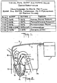
- FIG. 2 schematically illustrates the manner in which an apparatus 1, according to the invention, is provided as an implantable device in a manner similar to that commonly employed for permanently implanted pacemaking defibrillators.
- Leads 2 and 3 are inserted into the chambers of the heart including, respectively, the right atrium 5 and the right ventricle 6.
- Lead 3 is a dual ECG/VP lead placed to acquire the electrogram of and the pressure in the right ventricle 6.
- Apparatus 1 may use one or more epicardial defibrillation patches 7 connected to apparatus 1 by a lead 7A.
- the break in leads 2,3 and 7A signifies that apparatus 1 is to be implanted at a site removed from the cardiac cavity.
- FIG. 2 Also illustrated in FIG. 2 are the superior vena cava 8, the inferior vena cava 9, the left ventricle 10, the aorta 11, the pulmonary vessels 12 and the left atrium 13.
- FIG. 3 schematically illustrates the major circuit and logical units of apparatus 1 and its connection to the heart 4.
- the heart 4 is connected via the leads 2 and 3 and epicardial patch or patches 7 to the apparatus 1 by a top cap or neck connector 16.
- the analog signals sensed by the leads are filtered by a filter 18 then converted to a digital format by an A/D converter 19.
- the VP waveform from lead 3 is filtered with a bandpass or highpass filter 18A portion of filter 18, to remove D.C. offset and low frequency components.
- the digital signals are then processed by the main processing unit MPU 20 of apparatus 1.
- the MPU 20 controls the logic and circuitry of the bradycardia support pacing 21, ATP 22 and defibrillation 23 modules. It can be programmed by a telemetric link 25 and has random access to data storage registers of a memory 26.
- the digital signals from the pressure sensing lead are processed by a pressure processing unit P.P.U. 24 that is illustrated as a separate module, but may also be a logical unit within MPU 20.
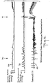
- FIG. 4 depicts a typical RVP waveform 28.
- FIG. 4 also depicts the typical form of the pressure wave obtained in the femoral artery, FAP 27, and a surface ECG 29. It can be seen that the modulations of both pressure waveforms fall in time between the R waves of the ECG.
- FIG. 5 shows that the peak-to-peak amplitude of the RVP 31 is well maintained even when the heart is paced to a high rate. It can also be seen that the FAP 30 at this rate is low, but is still life sustaining in the short term. It can also be seen that the peaks of the pressure waveform in the ventricle and the femoral artery both occur after the R wave of the surface ECG 32.
- FIG. 6 depicts the typical changes in FAP 33, RVP 34 and surface ECG 35 with the onset of ventricular fibrillation at 36. There is almost no modulation in either the FAP 33 or RVP 34 waveforms during well established VF and the FAP 33 is so low that life would cease unless prompt action were taken. Normal function is returned after the administration of a defibrillating shock at 37.
- the processing unit for the pressure waveform, PPU 24 in FIG. 3, derives the FPPA and VPPF from the filtered and digitized VP waveform.
- the PPU 24 communicates the derived data to the MPU 20.
- the MPU 20 has access to the data registers of a P.P.U. memory 24A of the PPU 24.
- the RVFPPA is obtained by filtering the VP waveform with a highpass filter with a -3 db frequency in the range of 0.1 to 0.5 Hz. In the preferred embodiments this filter is a second order Butterworth filter.
- the RVFPPA is derived from the filtered RVP waveform by determining the maximum excursion of the filtered signal over a defined time period. In the preferred embodiment this time period is determined by the period between R waves in the intracardiac ECG.
- the RVPPF is obtained by rectifying the filtered RVP waveform and then integrating it. The integral for each contraction is obtained by reference to the R wave interval from the endocardial ECG. In the preferred embodiments of this device both these signals are used to determine whether or not the recipient of the device is haemodynamically compromised.
- the device has two main implementations each of which can be implemented using one of two algorithms.
- the first algorithm hereafter referred to as the "simple threshold algorithm”
- the RVFPPA is monitored and compared to a threshold value.
- This value can be programmed as either an absolute value or as a percentage of a long term mean of the RVFPPA.
- the threshold detector is linked to a simple counter. Each time the value of the RVFPPA becomes greater than the threshold value a counter is reset to zero. This counter increments each time the RVFPPA is sensed to be less than the threshold value. If this counter reaches a pre-programmed value then haemodynamic compromise is deemed to exist. In the normally functioning recipient of this device the rising edge of the RVFPPA periodically resets the counter before the triggering value is reached. When the counter reaches the triggering level, the PPU 24 communicates this to the MPU 20 indicating that a state of haemodynamic compromise exists.
- the RVFPPA is assessed with each cycle as the sum of the greatest negative and positive digital values obtained over one cycle.
- the value is manipulated as a percentage of a programmed reference value and the values for the last Y beats are stored in memory, where Y is a programmed value.
- the RVPPF value is calculated as a percentage of a programmed value and the values for the last y beats are also stored in memory.
- X out of the last Y beats where X and Y are programmed values, fail to produce RVFPPA and/or RVPPF values above programmed levels, then the PPU 24 communicates this to the MPU 20 thus indicating that a state of haemodynamic compromise exists.
- the simplest case of this X out of Y test is with both X and Y equal to one.
- the average of the stored values is then used, in conjunction with information gained electrically about the heart rate, to determine what therapy to initiate as per FIG. 1. If apparatus 1 senses an electrical disturbance of the heart, then the MPU 20 interrogates the PPU 24 as to the haemodynamic state of the recipient of apparatus 1 to determine what therapy to initiate as per FIG. 1.
- apparatus 1 senses an electrical disturbance of the heart
- the MPU 20 activates the PPU 24 to derive the RVFPPA and RVPPF values and performs an X out of Y test as described above. Therapy is then initiated as per FIG. 1. No therapy will be initiated if there is no evidence of haemodynamic compromise.
- the MPU 20 also periodically activates the PPU 24 to ensure that the FPPA and VPPF are within optimal normal limits. If the FPPA and VPPF are not within normal limits, then the MPU 20 will initiate a pacing optimization algorithm as described below.
- Apparatus 1 may manipulate the A-V delay, paced heart rate and/or other pacing parameters to maximize the VP. As described below, it is principally implemented to manipulate A-V delay and heart rate. However since the manipulations involved are generally microprocessor based, any other programmed parameter can also be manipulated.
- bradycardia is defined in terms of an electrically sensed bradycardia with or without the pressure sensor detecting haemodynamic compromise.
- Asystole is defined in terms of the absence of electrical activity and of modulation in the RVFPPA.
- the invention can be implemented in one of the two embodiments using either of the sensing modes described above.
- the FPPA or VPPF are continuously derived.
- the haemodynamic sensor is activated only when an electrical abnormality in the function of the heart is detected.
- the MPU 20 continuously monitors the PPU 24 as well as the electrical activity of the heart.
- the result of the haemodynamic compromise detection algorithm is used in conjunction with information gained electrically about the heart rate, to determine what therapy to initiate. Since both electrical and haemodynamic function of the heart are being continuously sensed, an abnormality in the function of either can initiate therapy.
- the pacing optimization algorithm is continuously active during bradycardia support pacing.
- a dual chambered configuration allows the use of lower energy cardioversion shocks to revert atrial fibrillation that is haemodynamically compromising.
- This arrhythmia is recognized by the presence of an atrial rate that is higher than the ventricular rate in the presence of haemodynamic compromise.
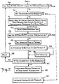
- FIG. 7 illustrates the logic behind the pacing optimization algorithm.
- This algorithm is designed to function with existing technologies; in particular with existing bradycardia support pacing, antitachycardia pacing and cardioverting/defibrillating therapies.
- the devices and/or logic blocks needed to implement these therapies in hardware or software are well known in the art.
- the first decision, at step 38 is whether or not one of the RVFPPA or RVPPF are within the programmed limits. If so, the program ends and eventually again returns to step 38. If not, then the presence of a tachyarrhythmia is tested for at step 39. If a tachyarrhythmia is present, the appropriate therapies are instituted at 40. In the preferred embodiments, the selection of which therapy is to be used is based on heart rate and haemodynamic parameters (FIG. 1).
- an optimization algorithm is initiated at 41 and the device begins to automatically alter pacing parameters.
- the parameters to be manipulated are specified by the clinician at implant of the device, or later via the telemetric link, and vary with the nature of the pacing strategies implemented in the device. If pacing is not already in operation, then the programmed stand-by rate is used as the starting point of the algorithm.
- the paced heart rate is varied within programmed upper and lower limits by sweeping up from the lowest rate to the highest rate in 5 b.p.m. steps.
- the range of values open to the clinician is 30 - 200 b.p.m.
- the clinician has the option to use any or all of the values in this range, to nominate the order in which they are used, and the starting and finishing point values.
- the A-V delay is varied within programmed upper and lower limits by sweeping up from the lowest rate to the highest rate in 20 millisecond steps.
- the range of values open to the clinician is 0 - 500 milliseconds.
- the clinician has the option to use any or all of the values in this range, to nominate the order in which they are to be used and the starting and finishing point values.
- the clinician also has the option to specify the precedence in which parameters are to be altered as well as the delay period between each change.
- the procedure is to sweep through each value of A-V delay in the programmed range, then select the next heart rate value in the programmed range, then sweep the A-V delay range again, etc. until the full range of both parameters has been swept and the point of maximal function obtained.
- the parameters that produce the best haemodynamic result are then selected at step 42.
- the function of the optimization algorithm is reinstituted after a programmed time has elapsed as determined at step 48, if a sub-optimal haemodynamic state still exists as determined by step 43. If the haemodynamic state has been optimized so as to be within acceptable limits, the program ends and eventually starts again at step 38. If the haemodynamic state is still sub-optimal, the fact that this has occurred will be stored in the memory of the microprocessor of MPU 20 at step 44. On the next occasion that the device is accessed via the telemetry link, this information will be available to the clinician.
- the apparatus has the capacity to warn the patient of the failure of the pacing optimization algorithm.
- This facility is capable of being activated or inactivated by the clinician via the telemetric link 25.
- a determination of whether the apparatus has been programmed to do so is made at step 45. If it has been so programmed, it will trigger a tactile warning to the patient at step 45 by way of a piezo-electric vibrating device attached to the inside of the can containing the apparatus.
- the clinician has the option to program the number of consecutive attempts that the device may make in trying to establish a stable haemodynamic state to thereby control the determination made at step 47.
- the clinician may also specify a set of default pacing parameters to be implemented at step 49, once this number of attempts has been made. If this should occur the algorithm cannot be reactivated except via the telemetric link.
- the logic for the algorithm is implemented via software.
- practice apparatus 1 is implanted and a series of electrophysiological studies are performed to guide the clinician in the choice of programmed variables.
- the resting state values of the patient's VFPPA and VPPF must be obtained.
- the performance of the apparatus can be maximized before the patient is discharged.
- the invention also may be implemented as a rate responsive pacemaker using open loop control based upon respiration.
- the algorithm is interrupted whenever a change in respiratory rate indicates that a change in heart rate is required. It is not re-instituted until a stable respiratory rate is again attained.
Claims (18)
- Vorrichtung zur Behandlung eines Herzens (4), mit:(a) einer Einrichtung zum Ermitteln eines Elektrogramms des Herzens;(b) eine Einrichtung zum Erfassen eines Signals, das den Herzkammerdruck anzeigt;(c) einer Prüfeinrichtung zum Prüfen des Elektrogramms, um zu bestimmen, ob eine Arrhythmie vorliegt; und(d) einer Therapieanwendungseinrichtung zum Anwenden einer Therapie auf das Herz;gekennzeichnet durch:(e) Verarbeitungseinrichtungen (18, 20, 24) zum Verarbeiten des Signals, um ein Signal zu erzeugen, das für mindestens eines repräsentativ ist bzw. mindestens eines darstellt, nämlich(i) eine gefilterte Spitze-zu-Spitze-Herzkammerdruckamplitude, die ermittelt wird, indem das Herzkammerdrucksignal gefiltert wird, um Basislinienänderungen des Herzkammerdrucksignals zu beseitigen, und danach die Spitze-zu-Spitze-Amplitude des gefilterten Signals bestimmt wird; oder(ii) eine Herzkammerspitzendruckfunktion, wobei das letztere das Integral eines gefilterten und gleichgerichteten Herzkammerdruckwellenformsignals aufweist;(f) einer Vergleichseinrichtung, die auf das repräsentative Signal anspricht, zum Bestimmen, ob mindestens eines, nämlich die Spitze-zu-Spitze-Herzkammerdruckamplitude oder die Herzkammerspitzendruckfunktion unter einem vorbestimmten Pegel ist;(g) einer Therapiewahleinrichtung, die auf die Vergleichseinrichtung und auf die Prüfeinrichtung anspricht, zum Wählen einer Therapie, die auf das Herz (4) anzuwenden ist, wenn mindestens eines, nämlich die gefilterte Spitze-zu-Spitze-Herzkammerdruckamplitude oder die Herzkammerspitzendruckfunktion unter dem vorbestimmten Pegel ist und eine Arrhythmie vorliegt.
- Vorrichtung nach Anspruch 1, bei der die Verarbeitungseinrichtung ein Hochpaßfilter (18A) zum Entfernen von niederfrequenten Komponenten aufweist.
- Vorrichtung nach Anspruch 2, bei der das Hochpaßfilter einen Punkt von -3dB im Bereich von 0,1 bis 0.5 Hz hat.
- Vorrichtung nach Anspruch 1, bei der die Verarbeitungsrichtung ein Bandpaßfilter (18) zum Entfernen von niederfrequenten Komponenten aufweist.
- Vorrichtung nach Anspruch 1, bei der das Elektrogramm und der Herzkammerdruck kontinuierlich erfaßt werden; und bei der die Verarbeitungseinrichtung kontinuierlich das repräsentative Signal erzeugt.
- Vorrichtung nach Anspruch 1, bei der das Elektrogramm kontinuierlich erfaßt wird und bei der die Verarbeitungseinrichtung das repräsentative Signal nur dann erzeugt, wenn vom Elektrogramm eine Arrhythmie angezeigt wird.
- Vorrichtung nach Anspruch 1, bei der die Therapiewahleinrichtung auf eine Bradykardie reagiert und die Therapieeinrichtung eine Stimulierungseinrichtung und einen Stimulierungsoptimierungsalgorithmus zum Optimieren der Stimulierung aufweist, um ein Anwachsen von mindestens einem, nämlich der gefilterten Spitze-zu-Spitze-Herzkammerdruckamplitude oder der Herzkammerspitzendruckfunktion zu erzeugen.
- Vorrichtung nach Anspruch 6, bei der der Stimulierungsoptimierungsalgorithmus verschiedene Werte der Herzfrequenz und der atrioventrikulären Verzögerung wählt.
- Vorrichtung nach Anspruch 1, bei der die Vergleichseinrichtung aufweist; einen Zähler, der auf eine Amplitude des repräsentativen Signals anspricht, wobei der Zähler zurückgesetzt wird, wenn die Amplitude einen vorbestimmten Pegel erreicht, wobei der Zähler erhöht wird, wenn die Amplitude einen vorbestimmten Pegel nicht erreicht; und eine Einrichtung zum Feststellen, wenn der Zählwert in dem Zähler einen vorbestimmten Wert erreicht, und um dann ein Eingabesignal an die Therapiewahleinrichtung zu liefern, das anzeigt, daß Therapie erforderlich ist.
- Vorrichtung nach Anspruch 1, bei der die Vergleichseinrichtung aufweist: eine Einrichtung zum Speichern von Amplitudenwerten von repräsentativen Signalen, die aus Y aufeinanderfolgenden Herzschlägen abgeleitet sind, und eine Einrichtung zum Bestimmen, ob X der gespeicherten Amplituden unter einem vorbestimmten Wert sind; und um dann ein Eingangssignal an die Therapiewahleinrichtung zu liefern, das anzeigt, daß Therapie erforderlich ist.
- Vorrichtung nach Anspruch 1, bei der das Herzkammerdruckwellenformsignal eine Druckwellenform der rechten Herzkammer (6) ist, die Therapiewahleinrichtung programmierbar und betriebsfähig ist, und zwar zum Bestimmen einer hämodynamischen Gefährdung auf der Grundlage des repräsentativen Signals und die Therapiewahleinrichtung und die Therapieanwendungseinrichtung betriebsfähig sind, und zwar zum Auslösen einer Antitachykardie-stimulierung und einer Kardioversion/Defibrillation auf der Grundlage der elektrischen und hämodynamischen Funktion des Herzens und zum Implementieren eines Verfahrens der Bradykardieunterstützungsstimulierungsoptimierung auf der Grundlage sowohl der elektrischen als auch der hämodynamischen Funktion des Herzens.
- Vorrichtung nach Anspruch 11, bei der mindestens eines. nämlich die Druckwellenform der linken Herzkammer (10), des rechten Herzvorhofs (5) oder des linken Herzvorhofs anstelle der oder in Verbindung mit der der rechten Herzkammer (6) verwendet wird.
- Vorrichtung nach Anspruch 11, bei der die Vorrichtung geeignet ist, elektrische Aktivität des Herzens (4) zu erfassen und das Herz in mindestens einem, nämlich dem rechten Herzvorhof (5), der rechten Herzkammer (6), dem linken Herzvorhof oder der linken Herzkammer (10) elektrisch zu stimulieren.
- Vorrichtung nach Anspruch 11, bei der die zweite Therapie-einrichtung auf Frequenz ansprechbar ist.
- Verfahren zum Bestimmen eines Index der hämodynamischen Funktion des Herzens (4) durch Überwachen des rechten Herzkammerdrucks, um eine Druckwellenform zu ermitteln, mit den Schritten: Hochpaßfilterung der Druckwellenform und Bestimmen der Spitze-zu-Spitze-Amplitude aus der gefilterten Druckwellenform, um einen Index der hämodynamischen Funktion zu bestimmen; oder Filterung und Gleichrichtung der Druckwellenform und anschließende Integrierung der gefilterten und gleichgerichteten Wellenform, um eine Spitzendruckfunktion zu erzeugen, die den hämodynamischen Index darstellt.
- Verfahren nach Anspruch 15, bei dem die Überwachung kontinuierlich implementiert wird.
- Verfahren nach Anspruch 15, bei dem die Überwachung intermittierend implementiert wird.
- Verfahren nach Anspruch 15, bei dem eine Druckwellenform von mindestens einem, nämlich der linken Herzkammer (10), dem rechten Herzvorhof (5) und dem linken Herzvorhof anstelle der oder in Verbindung mit der der rechten Herzkammer (6) verwendet wird.
Applications Claiming Priority (2)
| Application Number | Priority Date | Filing Date | Title |
|---|---|---|---|
| US481364 | 1990-02-16 | ||
| US07/481,364 US5083563A (en) | 1990-02-16 | 1990-02-16 | Implantable automatic and haemodynamically responsive cardioverting/defibrillating pacemaker |
Publications (3)
| Publication Number | Publication Date |
|---|---|
| EP0442601A2 EP0442601A2 (de) | 1991-08-21 |
| EP0442601A3 EP0442601A3 (en) | 1992-07-08 |
| EP0442601B1 true EP0442601B1 (de) | 1996-11-13 |
Family
ID=23911669
Family Applications (1)
| Application Number | Title | Priority Date | Filing Date |
|---|---|---|---|
| EP91300124A Expired - Lifetime EP0442601B1 (de) | 1990-02-16 | 1991-01-08 | Implantierbarer, auf hämodynamische Grössen ansprechender Herzschrittmacher zur automatischen Herzrhythmuskorrektur bzw. Defibrillation |
Country Status (6)
| Country | Link |
|---|---|
| US (1) | US5083563A (de) |
| EP (1) | EP0442601B1 (de) |
| JP (1) | JPH06327778A (de) |
| AU (1) | AU7013091A (de) |
| CA (1) | CA2034627A1 (de) |
| DE (1) | DE69123064T2 (de) |
Families Citing this family (82)
| Publication number | Priority date | Publication date | Assignee | Title |
|---|---|---|---|---|
| USRE38119E1 (en) | 1989-01-23 | 2003-05-20 | Mirowski Family Ventures, LLC | Method and apparatus for treating hemodynamic disfunction |
| US5184614A (en) * | 1990-10-19 | 1993-02-09 | Telectronics Pacing Systems, Inc. | Implantable haemodynamically responsive cardioverting/defibrillating pacemaker |
| DE69209324T2 (de) * | 1991-01-09 | 1996-11-21 | Medtronic Inc | Servosteuerung für Muskeln |
| US5158079A (en) * | 1991-02-25 | 1992-10-27 | Incontrol, Inc. | Implantable device for preventing tachyarrhythmias |
| US5282837A (en) * | 1991-04-12 | 1994-02-01 | Incontrol, Inc. | Atrial defibrillator and method |
| US5395393A (en) * | 1991-11-01 | 1995-03-07 | Telectronics Pacing Systems, Inc. | Intracardiac electrogram sensing in an arrhythmia control system |
| DE69307510T2 (de) * | 1992-06-30 | 1997-07-31 | Medtronic Inc | Vorrichtung zur behandlung von angina pectoris |
| FR2714761B1 (fr) * | 1993-12-31 | 1996-03-15 | Ela Medical Sa | Procédé de configuration d'un dispositif implantable actif par ajustage de paramètres. |
| US5626623A (en) * | 1996-04-30 | 1997-05-06 | Medtronic, Inc. | Method and apparatus for optimizing pacemaker AV delay |
| US7158830B2 (en) * | 1998-05-08 | 2007-01-02 | Cardiac Pacemakers, Inc. | Method and apparatus for optimizing stroke volume during DDD resynchronization therapy using adjustable atrio-ventricular delays |
| US7110817B2 (en) * | 1998-05-08 | 2006-09-19 | Cardiac Pacemakers, Inc. | Method and apparatus for optimizing ventricular synchrony during DDD resynchronization therapy using adjustable atrio-ventricular delays |
| SE0004224D0 (sv) * | 2000-11-16 | 2000-11-16 | St Jude Medical | Medical device |
| US7386344B2 (en) * | 2004-08-11 | 2008-06-10 | Cardiac Pacemakers, Inc. | Pacer with combined defibrillator tailored for bradycardia patients |
| US6751502B2 (en) | 2001-03-14 | 2004-06-15 | Cardiac Pacemakers, Inc. | Cardiac rhythm management system with defibrillation threshold prediction |
| KR100439193B1 (ko) * | 2001-12-04 | 2004-07-07 | 주식회사 씨유메디칼시스템 | 자동 제세동기 및 제세동 방법 |
| US6666826B2 (en) * | 2002-01-04 | 2003-12-23 | Cardiac Pacemakers, Inc. | Method and apparatus for measuring left ventricular pressure |
| US8321036B2 (en) * | 2002-02-15 | 2012-11-27 | Data Sciences International, Inc. | Cardiac rhythm management device |
| US20090088813A1 (en) * | 2004-03-12 | 2009-04-02 | Brockway Brian P | Cardiac Rhythm Management Device |
| US7041061B2 (en) * | 2002-07-19 | 2006-05-09 | Cardiac Pacemakers, Inc. | Method and apparatus for quantification of cardiac wall motion asynchrony |
| US7231249B2 (en) * | 2003-07-24 | 2007-06-12 | Mirowski Family Ventures, L.L.C. | Methods, apparatus, and systems for multiple stimulation from a single stimulator |
| US20050055057A1 (en) * | 2003-09-05 | 2005-03-10 | Mirowski Famliy Ventures, L.L.C. | Method and apparatus for providing ipselateral therapy |
| US20050055058A1 (en) | 2003-09-08 | 2005-03-10 | Mower Morton M. | Method and apparatus for intrachamber resynchronization |
| US9002452B2 (en) | 2003-11-07 | 2015-04-07 | Cardiac Pacemakers, Inc. | Electrical therapy for diastolic dysfunction |
| US7254451B2 (en) * | 2003-11-20 | 2007-08-07 | Medtronic, Inc. | Implantable lead including sensor |
| US7233822B2 (en) * | 2004-06-29 | 2007-06-19 | Medtronic, Inc. | Combination of electrogram and intra-cardiac pressure to discriminate between fibrillation and tachycardia |
| US7775966B2 (en) | 2005-02-24 | 2010-08-17 | Ethicon Endo-Surgery, Inc. | Non-invasive pressure measurement in a fluid adjustable restrictive device |
| US7699770B2 (en) | 2005-02-24 | 2010-04-20 | Ethicon Endo-Surgery, Inc. | Device for non-invasive measurement of fluid pressure in an adjustable restriction device |
| US7927270B2 (en) * | 2005-02-24 | 2011-04-19 | Ethicon Endo-Surgery, Inc. | External mechanical pressure sensor for gastric band pressure measurements |
| US7658196B2 (en) | 2005-02-24 | 2010-02-09 | Ethicon Endo-Surgery, Inc. | System and method for determining implanted device orientation |
| US8016744B2 (en) | 2005-02-24 | 2011-09-13 | Ethicon Endo-Surgery, Inc. | External pressure-based gastric band adjustment system and method |
| US7775215B2 (en) | 2005-02-24 | 2010-08-17 | Ethicon Endo-Surgery, Inc. | System and method for determining implanted device positioning and obtaining pressure data |
| US8066629B2 (en) | 2005-02-24 | 2011-11-29 | Ethicon Endo-Surgery, Inc. | Apparatus for adjustment and sensing of gastric band pressure |
| US9265949B2 (en) * | 2005-06-28 | 2016-02-23 | Cardiac Pacemakers, Inc. | Method and apparatus for controlling cardiac therapy based on electromechanical timing |
| US20070021680A1 (en) * | 2005-07-22 | 2007-01-25 | Transoma Medical, Inc. | Methods to reduce power to measure pressure |
| US7869871B2 (en) | 2006-03-31 | 2011-01-11 | Cardiac Pacemakers, Inc. | Pacing therapy for diastolic heart failure |
| US8870742B2 (en) | 2006-04-06 | 2014-10-28 | Ethicon Endo-Surgery, Inc. | GUI for an implantable restriction device and a data logger |
| US8152710B2 (en) * | 2006-04-06 | 2012-04-10 | Ethicon Endo-Surgery, Inc. | Physiological parameter analysis for an implantable restriction device and a data logger |
| US20080249806A1 (en) * | 2006-04-06 | 2008-10-09 | Ethicon Endo-Surgery, Inc | Data Analysis for an Implantable Restriction Device and a Data Logger |
| US20080250341A1 (en) * | 2006-04-06 | 2008-10-09 | Ethicon Endo-Surgery, Inc. | Gui With Trend Analysis for an Implantable Restriction Device and a Data Logger |
| US8014863B2 (en) * | 2007-01-19 | 2011-09-06 | Cardiac Pacemakers, Inc. | Heart attack or ischemia detector |
| US7810532B2 (en) * | 2007-03-29 | 2010-10-12 | Amana Tool Corporation | Router bit system and method for constructing tambours |
| EP2194856B1 (de) | 2007-09-14 | 2021-09-01 | Medtronic Monitoring, Inc. | Haftender herzmonitor |
| WO2009036334A1 (en) * | 2007-09-14 | 2009-03-19 | Corventis, Inc. | Adherent multi-sensor device with empathic monitoring |
| US20090076341A1 (en) * | 2007-09-14 | 2009-03-19 | Corventis, Inc. | Adherent Athletic Monitor |
| US8116841B2 (en) | 2007-09-14 | 2012-02-14 | Corventis, Inc. | Adherent device with multiple physiological sensors |
| WO2009036327A1 (en) * | 2007-09-14 | 2009-03-19 | Corventis, Inc. | Adherent device for respiratory monitoring and sleep disordered breathing |
| US20090076349A1 (en) * | 2007-09-14 | 2009-03-19 | Corventis, Inc. | Adherent Multi-Sensor Device with Implantable Device Communication Capabilities |
| US8897868B2 (en) * | 2007-09-14 | 2014-11-25 | Medtronic, Inc. | Medical device automatic start-up upon contact to patient tissue |
| US20090076343A1 (en) * | 2007-09-14 | 2009-03-19 | Corventis, Inc. | Energy Management for Adherent Patient Monitor |
| US8684925B2 (en) * | 2007-09-14 | 2014-04-01 | Corventis, Inc. | Injectable device for physiological monitoring |
| US20090076559A1 (en) * | 2007-09-14 | 2009-03-19 | Corventis, Inc. | Adherent Device for Cardiac Rhythm Management |
| WO2009036319A1 (en) * | 2007-09-14 | 2009-03-19 | Corventis, Inc. | Adherent emergency patient monitor |
| EP2200499B1 (de) * | 2007-09-14 | 2019-05-01 | Medtronic Monitoring, Inc. | Multi-sensor-patientenmonitor zum nachweis von bevorstehender herzdekompensation |
| US8187163B2 (en) * | 2007-12-10 | 2012-05-29 | Ethicon Endo-Surgery, Inc. | Methods for implanting a gastric restriction device |
| US8100870B2 (en) | 2007-12-14 | 2012-01-24 | Ethicon Endo-Surgery, Inc. | Adjustable height gastric restriction devices and methods |
| US20090171379A1 (en) * | 2007-12-27 | 2009-07-02 | Ethicon Endo-Surgery, Inc. | Fluid logic for regulating restriction devices |
| US8142452B2 (en) * | 2007-12-27 | 2012-03-27 | Ethicon Endo-Surgery, Inc. | Controlling pressure in adjustable restriction devices |
| US8377079B2 (en) | 2007-12-27 | 2013-02-19 | Ethicon Endo-Surgery, Inc. | Constant force mechanisms for regulating restriction devices |
| US8337389B2 (en) | 2008-01-28 | 2012-12-25 | Ethicon Endo-Surgery, Inc. | Methods and devices for diagnosing performance of a gastric restriction system |
| US8192350B2 (en) | 2008-01-28 | 2012-06-05 | Ethicon Endo-Surgery, Inc. | Methods and devices for measuring impedance in a gastric restriction system |
| US8591395B2 (en) | 2008-01-28 | 2013-11-26 | Ethicon Endo-Surgery, Inc. | Gastric restriction device data handling devices and methods |
| US20090192534A1 (en) * | 2008-01-29 | 2009-07-30 | Ethicon Endo-Surgery, Inc. | Sensor trigger |
| US7844342B2 (en) | 2008-02-07 | 2010-11-30 | Ethicon Endo-Surgery, Inc. | Powering implantable restriction systems using light |
| US20090204179A1 (en) * | 2008-02-07 | 2009-08-13 | Ethicon Endo-Surgery, Inc. | Powering implantable restriction systems using temperature |
| US8221439B2 (en) * | 2008-02-07 | 2012-07-17 | Ethicon Endo-Surgery, Inc. | Powering implantable restriction systems using kinetic motion |
| US8114345B2 (en) * | 2008-02-08 | 2012-02-14 | Ethicon Endo-Surgery, Inc. | System and method of sterilizing an implantable medical device |
| US8591532B2 (en) | 2008-02-12 | 2013-11-26 | Ethicon Endo-Sugery, Inc. | Automatically adjusting band system |
| US8057492B2 (en) * | 2008-02-12 | 2011-11-15 | Ethicon Endo-Surgery, Inc. | Automatically adjusting band system with MEMS pump |
| US8034065B2 (en) * | 2008-02-26 | 2011-10-11 | Ethicon Endo-Surgery, Inc. | Controlling pressure in adjustable restriction devices |
| US8233995B2 (en) | 2008-03-06 | 2012-07-31 | Ethicon Endo-Surgery, Inc. | System and method of aligning an implantable antenna |
| US8187162B2 (en) * | 2008-03-06 | 2012-05-29 | Ethicon Endo-Surgery, Inc. | Reorientation port |
| US20090228063A1 (en) * | 2008-03-06 | 2009-09-10 | Ethicon Endo-Surgery, Inc. | System and method of communicating with an implantable antenna |
| JP5405500B2 (ja) * | 2008-03-12 | 2014-02-05 | コーヴェンティス,インク. | 心調律に基づく心代償不全予測 |
| US8412317B2 (en) | 2008-04-18 | 2013-04-02 | Corventis, Inc. | Method and apparatus to measure bioelectric impedance of patient tissue |
| JP2011519665A (ja) | 2008-05-08 | 2011-07-14 | カーディアック ペースメイカーズ, インコーポレイテッド | 房室遅延時間計算システム |
| US7945324B2 (en) * | 2008-06-30 | 2011-05-17 | Data Sciences International, Inc. | Pressure sensing lead systems for implantable stimulators |
| US20100191310A1 (en) * | 2008-07-29 | 2010-07-29 | Corventis, Inc. | Communication-Anchor Loop For Injectable Device |
| WO2011050283A2 (en) | 2009-10-22 | 2011-04-28 | Corventis, Inc. | Remote detection and monitoring of functional chronotropic incompetence |
| US9451897B2 (en) * | 2009-12-14 | 2016-09-27 | Medtronic Monitoring, Inc. | Body adherent patch with electronics for physiologic monitoring |
| US20110152698A1 (en) * | 2009-12-23 | 2011-06-23 | Greenhut Saul E | Method and apparatus for blood pressure waveform baseline estimation and removal |
| US8965498B2 (en) | 2010-04-05 | 2015-02-24 | Corventis, Inc. | Method and apparatus for personalized physiologic parameters |
| KR20190082532A (ko) * | 2018-01-02 | 2019-07-10 | 한양대학교 산학협력단 | Uwb 레이더를 이용하는 부정맥 진단 방법 및 장치 |
Family Cites Families (23)
| Publication number | Priority date | Publication date | Assignee | Title |
|---|---|---|---|---|
| US3400709A (en) * | 1965-10-01 | 1968-09-10 | Statham Instrument Inc | Arterial blood pressure monitor |
| SE346468B (de) * | 1969-02-24 | 1972-07-10 | Lkb Medical Ab | |
| US3614955A (en) * | 1970-02-09 | 1971-10-26 | Medtronic Inc | Standby defibrillator and method of operation |
| US3716059A (en) * | 1970-08-24 | 1973-02-13 | Cardiac Resuscitator Corp | Cardiac resuscitator |
| US3942536A (en) * | 1971-03-15 | 1976-03-09 | Mieczyslaw Mirowski | Cardioverting device having single intravascular catheter electrode system and method for its use |
| US3893452A (en) * | 1974-07-09 | 1975-07-08 | Medtronic Inc | Blood pressure monitoring system |
| US4023563A (en) * | 1975-09-22 | 1977-05-17 | American Home Products Corporation | Apparatus and method for determining onset times of pulses and use thereof in computing interarterial blood pressure electromechanical interval |
| NL7512187A (nl) * | 1975-10-17 | 1977-04-19 | Philips Nv | Bloeddrukmeter. |
| US4080966A (en) * | 1976-08-12 | 1978-03-28 | Trustees Of The University Of Pennsylvania | Automated infusion apparatus for blood pressure control and method |
| US4291699A (en) * | 1978-09-21 | 1981-09-29 | Purdue Research Foundation | Method of and apparatus for automatically detecting and treating ventricular fibrillation |
| US4407288B1 (en) * | 1981-02-18 | 2000-09-19 | Mieczyslaw Mirowski | Implantable heart stimulator and stimulation method |
| US4802481A (en) * | 1984-07-19 | 1989-02-07 | Cordis Leads, Inc. | Apparatus for controlling pacing of a heart in response to changes in stroke volume |
| US4702253A (en) * | 1985-10-15 | 1987-10-27 | Telectronics N.V. | Metabolic-demand pacemaker and method of using the same to determine minute volume |
| US4770177A (en) * | 1986-02-18 | 1988-09-13 | Telectronics N.V. | Apparatus and method for adjusting heart/pacer relative to changes in venous diameter during exercise to obtain a required cardiac output. |
| US4791931A (en) * | 1987-08-13 | 1988-12-20 | Pacesetter Infusion, Ltd. | Demand pacemaker using an artificial baroreceptor reflex |
| US4774950A (en) * | 1987-10-06 | 1988-10-04 | Leonard Bloom | Hemodynamically responsive system for and method of treating a malfunctioning heart |
| US4967749A (en) * | 1987-10-06 | 1990-11-06 | Leonard Bloom | Hemodynamically responsive system for and method of treating a malfunctioning heart |
| US4901725A (en) * | 1988-01-29 | 1990-02-20 | Telectronics N.V. | Minute volume rate-responsive pacemaker |
| CA1327838C (fr) * | 1988-06-13 | 1994-03-15 | Fred Zacouto | Dispositif implantable de protection contre les affections liees a la coagulation sanguine |
| EP0347708A1 (de) * | 1988-06-16 | 1989-12-27 | Cardiac Pacemakers, Inc. | Hämodynamische Ermittlung von Tachyarrhyth |
| US4940053A (en) * | 1989-01-25 | 1990-07-10 | Siemens-Pacesetter, Inc. | Energy controlled rate-responsive pacemaker having automatically adjustable control parameters |
| US4945909A (en) * | 1989-06-06 | 1990-08-07 | Cook Pacemaker Corporation | Pacemaker with activity-dependent rate limiting |
| US4928638A (en) * | 1989-09-12 | 1990-05-29 | Overbeck Wayne W | Variable intake manifold |
-
1990
- 1990-02-16 US US07/481,364 patent/US5083563A/en not_active Expired - Lifetime
-
1991
- 1991-01-08 EP EP91300124A patent/EP0442601B1/de not_active Expired - Lifetime
- 1991-01-08 DE DE69123064T patent/DE69123064T2/de not_active Expired - Fee Related
- 1991-01-21 CA CA002034627A patent/CA2034627A1/en not_active Abandoned
- 1991-01-30 AU AU70130/91A patent/AU7013091A/en not_active Abandoned
- 1991-02-15 JP JP3042381A patent/JPH06327778A/ja active Pending
Also Published As
| Publication number | Publication date |
|---|---|
| JPH06327778A (ja) | 1994-11-29 |
| EP0442601A2 (de) | 1991-08-21 |
| DE69123064T2 (de) | 1997-04-10 |
| CA2034627A1 (en) | 1991-08-17 |
| US5083563A (en) | 1992-01-28 |
| EP0442601A3 (en) | 1992-07-08 |
| DE69123064D1 (de) | 1996-12-19 |
| AU7013091A (en) | 1991-08-22 |
Similar Documents
| Publication | Publication Date | Title |
|---|---|---|
| EP0442601B1 (de) | Implantierbarer, auf hämodynamische Grössen ansprechender Herzschrittmacher zur automatischen Herzrhythmuskorrektur bzw. Defibrillation | |
| US5105810A (en) | Implantable automatic and haemodynamically responsive cardioverting/defibrillating pacemaker with means for minimizing bradycardia support pacing voltages | |
| EP1624929B1 (de) | Gerät zur überwachung von lungenödem | |
| EP0488512B1 (de) | Implantierbarer, auf hämodynamische Grössen ansprechender Herzschrittmacher zur Herzrhythmuskorrektur bzw. Defibrillation | |
| EP0573461B1 (de) | Vorrichtung zur Unterscheidung von stabilen und instabilen ventriculären tachycardien | |
| US5251626A (en) | Apparatus and method for the detection and treatment of arrhythmias using a neural network | |
| US5697884A (en) | Cardiac assist device having circadian muscle simulation | |
| US5161527A (en) | Apparatus and method for detecting abnormal cardiac rhythms in dual chamber arrhythmia control system | |
| US5257621A (en) | Apparatus for detection of and discrimination between tachycardia and fibrillation and for treatment of both | |
| EP1572293B1 (de) | Stimulation eines atemnervs | |
| US5607385A (en) | Device and algorithm for a combined cardiomyostimulator and a cardiac pacer-carioverter-defibrillator | |
| EP0465241B1 (de) | Gerät mit neuronalen Netzwerken zur Detektion und Behandlung von Arrythmien | |
| US5562595A (en) | Multiple therapy cardiac assist device having battery voltage safety monitor | |
| US5741310A (en) | System and method for hemodynamic pacing in ventricular tachycardia | |
| EP1709993A1 (de) | Verfahren zur Überwachung von Herzversagen und Lungenödem basierend auf ventrikulären diastolischen Enddruck mit einem implantierbaren medizinischen Gerät | |
| JP2004536678A (ja) | 埋め込み可能医療デバイスにおいて高電圧および抗頻脈ペーシング治療の送出を制御する方法および装置 | |
| WO1993003791A1 (en) | Discrimination of ventricular tachycardia from ventricular fibrillation | |
| US5697952A (en) | Cardiac assist device having muscle augementation after confirmed arrhythmia and method | |
| US7672716B1 (en) | QT-based system and method for detecting and distinguishing dilated cardiomyopathy and heart failure using an implantable medical device |
Legal Events
| Date | Code | Title | Description |
|---|---|---|---|
| PUAI | Public reference made under article 153(3) epc to a published international application that has entered the european phase |
Free format text: ORIGINAL CODE: 0009012 |
|
| AK | Designated contracting states |
Kind code of ref document: A2 Designated state(s): DE FR GB IT NL SE |
|
| PUAL | Search report despatched |
Free format text: ORIGINAL CODE: 0009013 |
|
| AK | Designated contracting states |
Kind code of ref document: A3 Designated state(s): DE FR GB IT NL SE |
|
| 17P | Request for examination filed |
Effective date: 19920812 |
|
| 17Q | First examination report despatched |
Effective date: 19941107 |
|
| GRAG | Despatch of communication of intention to grant |
Free format text: ORIGINAL CODE: EPIDOS AGRA |
|
| GRAH | Despatch of communication of intention to grant a patent |
Free format text: ORIGINAL CODE: EPIDOS IGRA |
|
| GRAH | Despatch of communication of intention to grant a patent |
Free format text: ORIGINAL CODE: EPIDOS IGRA |
|
| GRAA | (expected) grant |
Free format text: ORIGINAL CODE: 0009210 |
|
| AK | Designated contracting states |
Kind code of ref document: B1 Designated state(s): DE FR GB IT NL SE |
|
| PG25 | Lapsed in a contracting state [announced via postgrant information from national office to epo] |
Ref country code: IT Free format text: LAPSE BECAUSE OF FAILURE TO SUBMIT A TRANSLATION OF THE DESCRIPTION OR TO PAY THE FEE WITHIN THE PRESCRIBED TIME-LIMIT;WARNING: LAPSES OF ITALIAN PATENTS WITH EFFECTIVE DATE BEFORE 2007 MAY HAVE OCCURRED AT ANY TIME BEFORE 2007. THE CORRECT EFFECTIVE DATE MAY BE DIFFERENT FROM THE ONE RECORDED. Effective date: 19961113 Ref country code: NL Free format text: LAPSE BECAUSE OF FAILURE TO SUBMIT A TRANSLATION OF THE DESCRIPTION OR TO PAY THE FEE WITHIN THE PRESCRIBED TIME-LIMIT Effective date: 19961113 |
|
| REF | Corresponds to: |
Ref document number: 69123064 Country of ref document: DE Date of ref document: 19961219 |
|
| ET | Fr: translation filed | ||
| PG25 | Lapsed in a contracting state [announced via postgrant information from national office to epo] |
Ref country code: SE Effective date: 19970213 |
|
| NLV1 | Nl: lapsed or annulled due to failure to fulfill the requirements of art. 29p and 29m of the patents act | ||
| PLBE | No opposition filed within time limit |
Free format text: ORIGINAL CODE: 0009261 |
|
| STAA | Information on the status of an ep patent application or granted ep patent |
Free format text: STATUS: NO OPPOSITION FILED WITHIN TIME LIMIT |
|
| 26N | No opposition filed | ||
| PGFP | Annual fee paid to national office [announced via postgrant information from national office to epo] |
Ref country code: GB Payment date: 19971230 Year of fee payment: 8 |
|
| PG25 | Lapsed in a contracting state [announced via postgrant information from national office to epo] |
Ref country code: GB Free format text: LAPSE BECAUSE OF NON-PAYMENT OF DUE FEES Effective date: 19990108 |
|
| GBPC | Gb: european patent ceased through non-payment of renewal fee |
Effective date: 19990108 |
|
| PGFP | Annual fee paid to national office [announced via postgrant information from national office to epo] |
Ref country code: FR Payment date: 20021218 Year of fee payment: 13 |
|
| PGFP | Annual fee paid to national office [announced via postgrant information from national office to epo] |
Ref country code: DE Payment date: 20030131 Year of fee payment: 13 |
|
| PG25 | Lapsed in a contracting state [announced via postgrant information from national office to epo] |
Ref country code: DE Free format text: LAPSE BECAUSE OF NON-PAYMENT OF DUE FEES Effective date: 20040803 |
|
| PG25 | Lapsed in a contracting state [announced via postgrant information from national office to epo] |
Ref country code: FR Free format text: LAPSE BECAUSE OF NON-PAYMENT OF DUE FEES Effective date: 20040930 |
|
| REG | Reference to a national code |
Ref country code: FR Ref legal event code: ST |