EP0442539A2 - Friction facing material amd carrier assembly - Google Patents
Friction facing material amd carrier assembly Download PDFInfo
- Publication number
- EP0442539A2 EP0442539A2 EP91106057A EP91106057A EP0442539A2 EP 0442539 A2 EP0442539 A2 EP 0442539A2 EP 91106057 A EP91106057 A EP 91106057A EP 91106057 A EP91106057 A EP 91106057A EP 0442539 A2 EP0442539 A2 EP 0442539A2
- Authority
- EP
- European Patent Office
- Prior art keywords
- facing
- assembly
- friction
- elastomeric material
- stripe
- Prior art date
- Legal status (The legal status is an assumption and is not a legal conclusion. Google has not performed a legal analysis and makes no representation as to the accuracy of the status listed.)
- Granted
Links
Images


Classifications
-
- F—MECHANICAL ENGINEERING; LIGHTING; HEATING; WEAPONS; BLASTING
- F16—ENGINEERING ELEMENTS AND UNITS; GENERAL MEASURES FOR PRODUCING AND MAINTAINING EFFECTIVE FUNCTIONING OF MACHINES OR INSTALLATIONS; THERMAL INSULATION IN GENERAL
- F16D—COUPLINGS FOR TRANSMITTING ROTATION; CLUTCHES; BRAKES
- F16D69/00—Friction linings; Attachment thereof; Selection of coacting friction substances or surfaces
- F16D69/04—Attachment of linings
-
- F—MECHANICAL ENGINEERING; LIGHTING; HEATING; WEAPONS; BLASTING
- F16—ENGINEERING ELEMENTS AND UNITS; GENERAL MEASURES FOR PRODUCING AND MAINTAINING EFFECTIVE FUNCTIONING OF MACHINES OR INSTALLATIONS; THERMAL INSULATION IN GENERAL
- F16D—COUPLINGS FOR TRANSMITTING ROTATION; CLUTCHES; BRAKES
- F16D13/00—Friction clutches
- F16D13/58—Details
- F16D13/72—Features relating to cooling
-
- F—MECHANICAL ENGINEERING; LIGHTING; HEATING; WEAPONS; BLASTING
- F16—ENGINEERING ELEMENTS AND UNITS; GENERAL MEASURES FOR PRODUCING AND MAINTAINING EFFECTIVE FUNCTIONING OF MACHINES OR INSTALLATIONS; THERMAL INSULATION IN GENERAL
- F16D—COUPLINGS FOR TRANSMITTING ROTATION; CLUTCHES; BRAKES
- F16D13/00—Friction clutches
- F16D13/58—Details
- F16D13/60—Clutching elements
- F16D13/64—Clutch-plates; Clutch-lamellae
-
- F—MECHANICAL ENGINEERING; LIGHTING; HEATING; WEAPONS; BLASTING
- F16—ENGINEERING ELEMENTS AND UNITS; GENERAL MEASURES FOR PRODUCING AND MAINTAINING EFFECTIVE FUNCTIONING OF MACHINES OR INSTALLATIONS; THERMAL INSULATION IN GENERAL
- F16D—COUPLINGS FOR TRANSMITTING ROTATION; CLUTCHES; BRAKES
- F16D69/00—Friction linings; Attachment thereof; Selection of coacting friction substances or surfaces
- F16D69/04—Attachment of linings
- F16D69/0408—Attachment of linings specially adapted for plane linings
-
- F—MECHANICAL ENGINEERING; LIGHTING; HEATING; WEAPONS; BLASTING
- F16—ENGINEERING ELEMENTS AND UNITS; GENERAL MEASURES FOR PRODUCING AND MAINTAINING EFFECTIVE FUNCTIONING OF MACHINES OR INSTALLATIONS; THERMAL INSULATION IN GENERAL
- F16D—COUPLINGS FOR TRANSMITTING ROTATION; CLUTCHES; BRAKES
- F16D13/00—Friction clutches
- F16D13/58—Details
- F16D13/60—Clutching elements
- F16D13/64—Clutch-plates; Clutch-lamellae
- F16D2013/642—Clutch-plates; Clutch-lamellae with resilient attachment of frictions rings or linings to their supporting discs or plates for allowing limited axial displacement of these rings or linings
-
- F—MECHANICAL ENGINEERING; LIGHTING; HEATING; WEAPONS; BLASTING
- F16—ENGINEERING ELEMENTS AND UNITS; GENERAL MEASURES FOR PRODUCING AND MAINTAINING EFFECTIVE FUNCTIONING OF MACHINES OR INSTALLATIONS; THERMAL INSULATION IN GENERAL
- F16D—COUPLINGS FOR TRANSMITTING ROTATION; CLUTCHES; BRAKES
- F16D69/00—Friction linings; Attachment thereof; Selection of coacting friction substances or surfaces
- F16D2069/005—Friction linings; Attachment thereof; Selection of coacting friction substances or surfaces having a layered structure
- F16D2069/007—Friction linings; Attachment thereof; Selection of coacting friction substances or surfaces having a layered structure comprising a resilient layer
-
- F—MECHANICAL ENGINEERING; LIGHTING; HEATING; WEAPONS; BLASTING
- F16—ENGINEERING ELEMENTS AND UNITS; GENERAL MEASURES FOR PRODUCING AND MAINTAINING EFFECTIVE FUNCTIONING OF MACHINES OR INSTALLATIONS; THERMAL INSULATION IN GENERAL
- F16D—COUPLINGS FOR TRANSMITTING ROTATION; CLUTCHES; BRAKES
- F16D69/00—Friction linings; Attachment thereof; Selection of coacting friction substances or surfaces
- F16D69/04—Attachment of linings
- F16D2069/0425—Attachment methods or devices
- F16D2069/045—Bonding
- F16D2069/0466—Bonding chemical, e.g. using adhesives, vulcanising
Landscapes
- Engineering & Computer Science (AREA)
- General Engineering & Computer Science (AREA)
- Mechanical Engineering (AREA)
- Braking Arrangements (AREA)
- Mechanical Operated Clutches (AREA)
Abstract
Description
- This invention relates to a friction facing material and carrier assembly for a clutch driven plate, and also relates to a method of making such an assembly.
- In particular, though not exclusively, the clutch driven plate may be used in a clutch for a motor vehicle.
- The friction facing and carrier assembly concerned is of a type (hereinafter called "the type referred to") comprising at least one annular friction facing adhered to a carrier by elastomeric material, and in use said assembly being intended for rotation about an axis.
- It has already been proposed to apply the elastomeric material in the form of radially spaced stripes disposed as substanitially concentric circles substantially centred on said axis. Each stripe is substantially continuous with a view of maximising the bond strength of the elastomeric material. Unfortunately a plurality of nozzles are needed each for extruding a respective stripe onto the annular array of friction material rotating about an axis. Also the starting and finishing of extruding can be difficult to control precisely, and thus excessive blobs of elastomeric material may be deposited on the friction material.
- One object of the invention is to provide an assembly of the type referred to in which said drawbacks may be avoided or at least mitigated.
- According to one aspect of the invention a friction facing and carrier assembly of the type referred to is characterised in that said elastomeric material is disposed as a stripe extending about said axis, the facing for at least one full turn, and also extending from substantially its radially outermost edge to substantuate the radially innermost edge of the facing
- According to another aspect of the invention a method of making an annular friction facing and carrier assembly in which an annular friction facing is adhered to the carrier by a continuous stripe of elastomeric material characterized in that the stripe of elastomeric material is extruded from a nozzle moving between a radially innermost and a radially outermost position of the facing relative to said axis of rotation of the facings as the annular facing is rotated about said axis.
- Preferably the end of the strip is adjacent the outer edge of the facing and the other end of the strip is adjacent the inner edge of a facing.
- The elastomer may be a silicone rubber which vulcanises at room temperature so that distortion by vulcanisation heating may be avoided.
- The elastomer may have the following physical specifications:-

- The invention will now be further described by way of example, with reference to the accompanying drawings in which:-
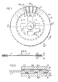
- Fig 1 is a plan view of a fragment of an embodiment of a friction material and carrier assembly formed according to the invention and intended to form a part of a dry friction clutch driven plate;
- Fig 2 is a section on line II-II in Fig 1;
- Fig 3 is a section on an enlarged scale on line III-III in Fig 1;
- Fig 4 is a section on an enlarged scale on line IV-IV in Fig 1;
- Fig 5 is a fragment on an enlarged scale of a friction facing in the course of a method of making the assembly in Fig 1;
- Fig 6 is a plan view of a friction facing with a spiral stripe of elastomer to be used in the friction material and carrier assembly shown in Fig 1:
- Fig 7 is a plan view of the other friction facing with a spiral stripe of elastomer to be used in the assembly in Fig 1, and
- Fig 8 is a view similar to Fig 3 of a modification.
- In the drawings like or comparable parts have the same reference numerals.
- With reference to the drawings a friction material and carrier plate assembly is shown at 2 intended to form part of a friction clutch driven plate which can be used in a clutch, for example a diaphragm spring clutch which may be used, for example in a motor vehicle.
- The assembly comprises a mainly flat
steel carrier plate 4 of disc form centrally apertured at 6 to fit, for example on an internally splined hub (not shown) known per se when the assembly is incorporated in a said driven plate.Aperture 6 is surrounded by a flared or Bellevillemarginal portion 8. Also the carrier plate is formed with windows 10̸ for torsional vibration damping springs (not shown) known per se and holes 12 for stop rivets (not shown) known per se. - At its periphery the
carrier plate 4 has a plurality of outwardly projecting paddles orspokes 14 integral with the main body of the carrier plate. The spokes are flat being substantially co-planar with the main body of the carrier plate and are substantially equi-angularly spaced about a central axis X about which theassembly 2 is intended to rotate in use.Slots 16 space the spokes which have substantially radialopposite edges 18. - In the example shown there are thirty
spokes 14 and thirtyslots 16. Circumferentially eachspoke 14 extends over about 7 degrees of arc and eachslot 16 over about 5 degrees. If desired the number, size, shape and spacing of the spokes can be varied. - The
spokes 14 are axially pliable in the sense of being leaf springs capable of flexing resiliently along directions substantially parallel to the axis X. This enables thecarrier plate 4 at thespokes 14 to be sinuously flexible circumferentially. - Two substantially coincident and co-axial annular friction facings 20̸ and 22 are respectively bonded by an
elastomeric material spoke 14. Theelastomeric material spokes 14. Theelastomeric material - Desirably the rubber is of a kind which can withstand temperatures experienced by friction facings in use without use rubber degrading to lose its necessary bond strength or resilience. It is believed that the rubber should be able withstand temperatures from approximately minus 30 degrees Centigrade up to about 250 degrees Centigrade, but an ability to withstand higher temperatures is thought desirable, for example up to about 300 degrees Centigrade or higher.
- The
elastomeric material 24 is in the form of a spiral bead or stripe which is continuous from its outermost end to its innermost end and is substantially centred on the axis X, and, in this example, comprises threeturns elastomeric material 25 is also in the form of a continuous spiral bead or stripe and comprises threeturns elastomeric material 25 is superimposed as it would appear when both the friction facings are bonded onto the carrier plate. - Each friction facing 20,22 can be formed of any suitable friction material and may be of a non-asbestos type, but the facings are somewhat resilient such that each facing can flex or deform at least circumferentially.
- The
facings - Due to the sinuous flexibility of the
carrier plate 4 and the resilient and flexible nature of the friction facings 20 and 22, the whole of the friction facings andcarrier plate assembly 2 is sinuously flexible circumferentially at thespokes 14. - The layers of
elastomer paddles 14 and an overall axial cushioning between the friction facings, Thelayers - However when the
assembly 2 forms part of a clutch driven plate in use in a motor vehicle clutch such as a diaphragm spring clutch, the subjective feel and quality of clutch re-engagements may be further enhanced by provision of further cushioning such as between the pressure plate and diaphragm spring and/or between the diaphragm spring and a clutch cover. That further cushioning may be a wavy wire fulcrum ring as in British Patent No. 1 583 40̸3. - Since the
elastomeric bonding material 24 is to be used in a clutch driven plate it has to have both the aforesaid resistance to degradation by heat and also have good shear strength in both the mass of elastomeric material and in the bonds it forms between itself and the friction facings and paddles. - To manufacture a friction material and carrier plate assembly as described above, the
spirals - As shown in Figs 5 to 7 during manufacture of the assembly 2 (Fig 1) the elastomeric material is applied as a paste in substantially the form of a spiral stripe or
bend paddles 14 and vulcanised. In the case of an RTV rubber vulcanising is merely by subjecting the paste to the appropriate room temperature and humidity for sufficient time. For example RTV 7057 vulcanises in about forty-eight hours at a temperature of about 25 degrees Centigrade and about 50% relative humidity. - When the friction facings bearing the elastomer spirals and the carrier plate are laid up together, it is ensured that, relative to the axis X, the
spiral 24 is angularly off-set, in this example by substantially 180 degrees, relative to thespiral 25 so that as shown in Figs 3 and 4 (and by thespiral 25 shown by the dash line in Fig 6) each turn of one spiral is opposite the gap between adjacent turns of the other spiral. Thus at eachslot 16 there is a generally radially extending passage (such a passage being indicated in Fig 4 by the double headed arrows a). Those passages allow gases, emitted by the elastomeric stripes during curing of the elastomer, to escape. The passages also allow the ambient atmosphere to have full access to both complete opposite sides of each spiral stripe of elastomeric material. Furthermore by incorporating two spirals of elastomer which are of the same hand when in the assembly of friction facings and carrier plate and which are offset by substantially 180 degrees, the spirals do not cross at any point and there is no overlap which might create a blob of elastomer. - Each spiral stripe of elastomer can be applied to its respective annular friction facing by rotating the friction facing about its axis and simultaneously extruding the elastomer from a nozzle moving across the annular friction facing (for example substantially radially with respect to said axis) from the outer periphery of the facing towards the inner periphery or vice-versa. Conveniently the nozzle applies or lays one spiral stripe of elastomer onto a first friction facing whilst traversing from the outer periphery to the inner periphery of the facing and then the nozzle applies or lays another spiral stripe onto a second friction facing whilst traversing from the inner periphery to the outer periphery of the second facing. The second facing is then rotated through 180 degrees as described above before both the first and second facings are laid up onto the carrier plate.
Preferably each spiral of elastomer has a substantially constant cross-section (radially of the axis of the friction facing) throughout its length. This may be achieved by varying the rate at which elastomer is extruded so that the rate of extrusion is in a direct proportion to the distance of the nozzle from the axis of rotation of the friction facing and/or by varying the speed of rotation of the annular friction facing so that at any instant the speed is in an inverse proportion to the distance of the nozzle from the axis of rotation. - In an alternative method each friction facing can be maintained substantially stationary whilst a nozzle extruding the elastomer moves along a spiral path about the axis of the friction facing to lay down the sprial stripe of elastomer between the inner and outer peripheries of the friction facing. The nozzle can follow the spiral path in one direction for one friction facing and then follow the spiral path in the opposite direction for the next friction facing. If the nozzle is moved at a substantially constant linear speed, then the elastomer stripe extruded has a substantially constant cross-section (radially of the axis of the friction facing) throughout its length.
- Also, preferably, throughout the length of a spiral of elastomer, the distance between adjacent turns is substantially constant. However there may be an advantage in ensuring that the width of the gap between turns of the spiral decreases in size the closer the spiral gets to the outer periphery of the annulus of friction material. This means the concentration of turns of the spiral varies across the annulus and is greater the nearer the approach to the outer periphery.
- Any of the spirals, for example the spiral 25 in Fig 7, could have its outer or inner end at Y or Z for example, instead of those ends coinciding with the outer and inner peripheries of the friction material as shown. That coincidence is ensured by commencing extrusion of the elastomer from the nozzle before the nozzle crosses the outer or inner periphery of the friction facing to begin laying the spiral on the friction facing and to continue extrusion after the complete spiral is laid and the nozzle has crossed the inner or outer periphery of the friction facing. Thus adjacent to the outer and inner peripheries the nozzle extrudes
waste portions - It may be desired, as shown in Fig.8, for the radial cross-sectional area of the spiral of elastomer to vary from one end to the other of the spiral. For example, at any given position the radial cross-section of the spiral thereat can be greater the nearer that position is to the radially inner end of the spiral. Therefore the cross-section shown of
turn 25A in Fig.8 is smaller than that shown ofturn 25B which is smaller than that shown ofturn 25C. To achieve a more uniform distribution of (externally applied) pressure radially across each friction facing, the radial gap between adjacent turns of a spiral decreases the further the gap is radially from the axis X such that gap b is less than gap c.
Claims (10)
- A friction facing material and carrier assembly (2) for a clutch driven plate, said assembly (2) being intended for rotation about an axis (X) and comprising at least one annular array of friction material (20̸;22) adhered to the carrier by elastomeric material (24;25), characterised in that said elastomeric material is disposed as a continuous stripe (24;25) extending around the annular facing about said axis (X) for at least one turn and also extending from the radially outermost edge to the substantially continuous radially innermost edge of said facing.
- An assembly as claimed in Claim 1, cgharacterised in that the elastomeric material is a silicone rubber.
- An assembly as claimed in Claim 1 or Claim 2 characterised in that the stripe has a radially outermost end adjacent the radially outermost edge of the facing and a radially inner end adjacent with the inner edge of the friction facing.
- An assembly as claimed in any one of Claims 1 to 3 characterised in that said stripe end of elastomer has a substantially constant cross section throughout its length.
- An assembly as claimed in any one preceding claim, characterised in that said friction facing material (20̸;22) is adhered as aforesaid to paddles (14) at the outer periphery of said carrier (4).
- An assembly as claimed in Claim 5 characterised in that each paddle (14) can flex resiliently.
- An assembly as claimed in any one preceding claim, characterised in that there are two said annular facings of friction material and each is adhered as aforesaid to a respective opposite side of the carrier.
- A method of making as an annular friction facing and carrier assembly (2) in which an annular friction facing is adhered to the carrier by a continuous stripe of elastomeric material characterised in tha the stripe of elastomeric material is extended from a nozzle moving between a radially innermost and a radially outermost postion of the facing relative to the axis (X) of rotation of the facing as relative rotation takes place between the facing and the nozzle.
- A method of making an assembly (2) as claimed in Claim 7 characterized in that said method comprises extruding the stripe of elastomeric material between inner and outer peripheries of the friction facing so that the rate of extension is proportioned to the distance of the nozzle from the axis of rotation so that the linear speed of the nozzle relative to the facing is substantially constant.
- A clutch driven plate characterized in that it comprises an assembly (2) as claimed in any one of Claims 1 to 14 or when made by the method claimed in any one of Claims 15 to 18.
Applications Claiming Priority (3)
| Application Number | Priority Date | Filing Date | Title |
|---|---|---|---|
| GB878730164A GB8730164D0 (en) | 1987-12-24 | 1987-12-24 | Friction facing material & carrier assembly |
| GB8730164 | 1987-12-24 | ||
| EP88311313A EP0323036B1 (en) | 1987-12-24 | 1988-11-30 | Friction facing material and carrier assembly |
Related Parent Applications (1)
| Application Number | Title | Priority Date | Filing Date |
|---|---|---|---|
| EP88311313.6 Division | 1988-11-30 |
Publications (3)
| Publication Number | Publication Date |
|---|---|
| EP0442539A2 true EP0442539A2 (en) | 1991-08-21 |
| EP0442539A3 EP0442539A3 (en) | 1992-10-28 |
| EP0442539B1 EP0442539B1 (en) | 1994-08-17 |
Family
ID=10629067
Family Applications (2)
| Application Number | Title | Priority Date | Filing Date |
|---|---|---|---|
| EP91106057A Expired - Lifetime EP0442539B1 (en) | 1987-12-24 | 1988-11-30 | Friction facing material amd carrier assembly |
| EP88311313A Expired - Lifetime EP0323036B1 (en) | 1987-12-24 | 1988-11-30 | Friction facing material and carrier assembly |
Family Applications After (1)
| Application Number | Title | Priority Date | Filing Date |
|---|---|---|---|
| EP88311313A Expired - Lifetime EP0323036B1 (en) | 1987-12-24 | 1988-11-30 | Friction facing material and carrier assembly |
Country Status (10)
| Country | Link |
|---|---|
| US (1) | US5076410A (en) |
| EP (2) | EP0442539B1 (en) |
| JP (1) | JP2706543B2 (en) |
| KR (1) | KR970005075B1 (en) |
| AT (1) | ATE69295T1 (en) |
| AU (1) | AU2810989A (en) |
| DE (2) | DE3851157T2 (en) |
| GB (2) | GB8730164D0 (en) |
| WO (1) | WO1989005927A1 (en) |
| ZA (1) | ZA889303B (en) |
Cited By (3)
| Publication number | Priority date | Publication date | Assignee | Title |
|---|---|---|---|---|
| US5196081A (en) * | 1987-12-09 | 1993-03-23 | Automotive Products Plc | A method for a friction facing material and carrier assembly |
| WO2001096163A1 (en) | 2000-06-13 | 2001-12-20 | Automotive Products Uk Limited | Vehicle clutches |
| DE102008040962A1 (en) | 2007-09-13 | 2009-03-19 | Zf Friedrichshafen Ag | Method for establishing a connection between a clutch disc and a friction lining and clutch disc |
Families Citing this family (16)
| Publication number | Priority date | Publication date | Assignee | Title |
|---|---|---|---|---|
| GB8901880D0 (en) * | 1989-01-27 | 1989-03-15 | Automotive Prod Plc | Friction facing material and carrier assembly |
| GB2240142B (en) * | 1990-01-10 | 1994-02-23 | Automotive Products Plc | A friction facings and carrier assembly |
| GB2247725B (en) * | 1990-09-08 | 1994-07-27 | Automotive Products Plc | A friction facings and carrier assembly |
| FR2673984B1 (en) * | 1991-03-12 | 1995-05-05 | Valeo | PROGRESSIVE FRICTION DISC FOR DRY FRICTION CLUTCH. |
| US5358080A (en) * | 1992-12-09 | 1994-10-25 | The Budd Company | Reinforced brake rotor |
| GB9304004D0 (en) * | 1993-02-26 | 1993-04-14 | Automotive Products Plc | Friction clutch carrier assembly |
| DE4430280A1 (en) * | 1994-08-26 | 1996-02-29 | Bayerische Motoren Werke Ag | Internally ventilated brake disc for vehicle |
| SE504481C2 (en) * | 1995-06-26 | 1997-02-17 | Volvo Penta Ab | Transmission device, in particular reverse gear for boats |
| DE19737054C5 (en) * | 1997-08-26 | 2007-02-15 | Zf Sachs Ag | Friction clutch with power operated actuator |
| US7040475B2 (en) * | 2003-10-08 | 2006-05-09 | General Motors Corporation | Wet clutch friction member with dual-directional moduli of elasticity |
| CA2727039C (en) * | 2007-06-06 | 2015-07-21 | Robert G. Drysdale | Stable unbonded fiber-reinforced elastomeric seismic isolators for base isolation system |
| US20090000884A1 (en) * | 2007-06-26 | 2009-01-01 | Akebono Corporation (North America) | Brake rotor |
| DE102008005835B4 (en) * | 2008-01-24 | 2010-04-01 | Diehl Metall Stiftung & Co. Kg | Reibschichtträgervorrichtung and methods for manufacturing the Reibschichtträgervorrichtung |
| WO2020009192A1 (en) * | 2018-07-06 | 2020-01-09 | 株式会社デンソー | Clutch device |
| JP6685070B1 (en) * | 2019-10-25 | 2020-04-22 | 株式会社エフ・シー・シー | Joined parts, multi-disc clutch device including the joined parts, and method for manufacturing joined parts |
| CN112492459B (en) * | 2020-12-09 | 2021-12-10 | 共达电声股份有限公司 | Loudspeaker |
Citations (2)
| Publication number | Priority date | Publication date | Assignee | Title |
|---|---|---|---|---|
| GB2191830A (en) * | 1986-06-18 | 1987-12-23 | Automotive Products Plc | Clutch friction material and carrier plate assembly |
| EP0252583A2 (en) * | 1986-06-28 | 1988-01-13 | Automotive Products Public Limited Company | Friction facing material and carrier assembly |
Family Cites Families (10)
| Publication number | Priority date | Publication date | Assignee | Title |
|---|---|---|---|---|
| US2253316A (en) * | 1938-07-26 | 1941-08-19 | Borg Warner | Rivetless drive plate |
| GB611823A (en) * | 1946-05-09 | 1948-11-04 | Ferodo Ltd | Improvements in and relating to friction clutches |
| FR86502E (en) * | 1960-04-13 | 1966-02-25 | Method and device for transmitting and braking a rotational movement | |
| US3231058A (en) * | 1962-02-19 | 1966-01-25 | Raybestos Manhattan Inc | Friction device |
| US3520390A (en) * | 1968-02-08 | 1970-07-14 | Raybestos Manhattan Inc | Clutch facing |
| GB2027822A (en) * | 1978-08-12 | 1980-02-27 | Automotive Prod Co Ltd | Friction clutch driven plates |
| US4529079A (en) * | 1980-01-16 | 1985-07-16 | Borg-Warner Corporation | Cushion-bonded driven disc assembly and method of construction |
| EP0186261A1 (en) * | 1984-11-24 | 1986-07-02 | Automotive Products Public Limited Company | Friction material and carrier plate assembly |
| GB8503611D0 (en) * | 1985-02-12 | 1985-03-13 | Automotive Prod Plc | Friction material & carrier plate assembly |
| GB8817493D0 (en) * | 1988-07-22 | 1988-08-24 | Ferodo Ltd | Method & apparatus for assembly of friction components |
-
1987
- 1987-12-24 GB GB878730164A patent/GB8730164D0/en active Pending
-
1988
- 1988-11-30 DE DE3851157T patent/DE3851157T2/en not_active Expired - Fee Related
- 1988-11-30 KR KR1019890701263A patent/KR970005075B1/en not_active IP Right Cessation
- 1988-11-30 AU AU28109/89A patent/AU2810989A/en not_active Abandoned
- 1988-11-30 EP EP91106057A patent/EP0442539B1/en not_active Expired - Lifetime
- 1988-11-30 AT AT88311313T patent/ATE69295T1/en not_active IP Right Cessation
- 1988-11-30 WO PCT/GB1988/001045 patent/WO1989005927A1/en unknown
- 1988-11-30 DE DE8888311313T patent/DE3866093D1/en not_active Expired - Lifetime
- 1988-11-30 EP EP88311313A patent/EP0323036B1/en not_active Expired - Lifetime
- 1988-11-30 JP JP1500075A patent/JP2706543B2/en not_active Expired - Fee Related
- 1988-12-13 ZA ZA889303A patent/ZA889303B/en unknown
-
1990
- 1990-05-17 GB GB9011123A patent/GB2240824B/en not_active Expired - Lifetime
-
1991
- 1991-01-22 US US07/644,409 patent/US5076410A/en not_active Expired - Lifetime
Patent Citations (2)
| Publication number | Priority date | Publication date | Assignee | Title |
|---|---|---|---|---|
| GB2191830A (en) * | 1986-06-18 | 1987-12-23 | Automotive Products Plc | Clutch friction material and carrier plate assembly |
| EP0252583A2 (en) * | 1986-06-28 | 1988-01-13 | Automotive Products Public Limited Company | Friction facing material and carrier assembly |
Cited By (4)
| Publication number | Priority date | Publication date | Assignee | Title |
|---|---|---|---|---|
| US5196081A (en) * | 1987-12-09 | 1993-03-23 | Automotive Products Plc | A method for a friction facing material and carrier assembly |
| WO2001096163A1 (en) | 2000-06-13 | 2001-12-20 | Automotive Products Uk Limited | Vehicle clutches |
| DE102008040962A1 (en) | 2007-09-13 | 2009-03-19 | Zf Friedrichshafen Ag | Method for establishing a connection between a clutch disc and a friction lining and clutch disc |
| EP2039951A2 (en) | 2007-09-13 | 2009-03-25 | ZF Friedrichshafen AG | Method for producing a connection between a coupling disc and a friction lining and coupling disc |
Also Published As
| Publication number | Publication date |
|---|---|
| AU2810989A (en) | 1989-07-19 |
| EP0323036B1 (en) | 1991-11-06 |
| ATE69295T1 (en) | 1991-11-15 |
| EP0323036A1 (en) | 1989-07-05 |
| GB2240824A (en) | 1991-08-14 |
| ZA889303B (en) | 1989-09-27 |
| JP2706543B2 (en) | 1998-01-28 |
| GB9011123D0 (en) | 1990-08-01 |
| EP0442539A3 (en) | 1992-10-28 |
| DE3866093D1 (en) | 1991-12-12 |
| US5076410A (en) | 1991-12-31 |
| GB2240824B (en) | 1992-02-26 |
| DE3851157T2 (en) | 1995-03-09 |
| EP0442539B1 (en) | 1994-08-17 |
| WO1989005927A1 (en) | 1989-06-29 |
| JPH03505620A (en) | 1991-12-05 |
| KR970005075B1 (en) | 1997-04-12 |
| GB8730164D0 (en) | 1988-02-03 |
| KR900700790A (en) | 1990-08-17 |
| DE3851157D1 (en) | 1994-09-22 |
Similar Documents
| Publication | Publication Date | Title |
|---|---|---|
| EP0442539B1 (en) | Friction facing material amd carrier assembly | |
| US4821860A (en) | Friction facing material and carrier assembly | |
| US5199540A (en) | Friction facing material and carrier assembly | |
| US5551549A (en) | Friction facing and carrier assembly | |
| EP0510014B1 (en) | A fricton facings and carrier assembly | |
| KR0184868B1 (en) | Low inertia friction clutch especially for an automotive vehicle | |
| GB2191830A (en) | Clutch friction material and carrier plate assembly | |
| US5196081A (en) | A method for a friction facing material and carrier assembly | |
| WO1989005411A1 (en) | Friction facing material and carrier assembly | |
| GB2191831A (en) | Friction material and carrier plate assembly | |
| GB2247725A (en) | Friction facing and carrier assembly | |
| WO1991010837A1 (en) | Bonding method and assembly for use therein |
Legal Events
| Date | Code | Title | Description |
|---|---|---|---|
| PUAI | Public reference made under article 153(3) epc to a published international application that has entered the european phase |
Free format text: ORIGINAL CODE: 0009012 |
|
| 17P | Request for examination filed |
Effective date: 19910425 |
|
| AC | Divisional application: reference to earlier application |
Ref document number: 323036 Country of ref document: EP |
|
| AK | Designated contracting states |
Kind code of ref document: A2 Designated state(s): DE ES FR GB IT |
|
| PUAL | Search report despatched |
Free format text: ORIGINAL CODE: 0009013 |
|
| AK | Designated contracting states |
Kind code of ref document: A3 Designated state(s): DE ES FR GB IT |
|
| 17Q | First examination report despatched |
Effective date: 19931028 |
|
| GRAA | (expected) grant |
Free format text: ORIGINAL CODE: 0009210 |
|
| AC | Divisional application: reference to earlier application |
Ref document number: 323036 Country of ref document: EP |
|
| AK | Designated contracting states |
Kind code of ref document: B1 Designated state(s): DE ES FR GB IT |
|
| PG25 | Lapsed in a contracting state [announced via postgrant information from national office to epo] |
Ref country code: ES Free format text: THE PATENT HAS BEEN ANNULLED BY A DECISION OF A NATIONAL AUTHORITY Effective date: 19940817 |
|
| REF | Corresponds to: |
Ref document number: 3851157 Country of ref document: DE Date of ref document: 19940922 |
|
| ITF | It: translation for a ep patent filed |
Owner name: JACOBACCI CASETTA & PERANI S.P.A. |
|
| ET | Fr: translation filed | ||
| PLBE | No opposition filed within time limit |
Free format text: ORIGINAL CODE: 0009261 |
|
| STAA | Information on the status of an ep patent application or granted ep patent |
Free format text: STATUS: NO OPPOSITION FILED WITHIN TIME LIMIT |
|
| 26N | No opposition filed | ||
| REG | Reference to a national code |
Ref country code: GB Ref legal event code: 732E |
|
| REG | Reference to a national code |
Ref country code: GB Ref legal event code: 732E |
|
| REG | Reference to a national code |
Ref country code: GB Ref legal event code: IF02 |
|
| PGFP | Annual fee paid to national office [announced via postgrant information from national office to epo] |
Ref country code: FR Payment date: 20021010 Year of fee payment: 15 |
|
| PGFP | Annual fee paid to national office [announced via postgrant information from national office to epo] |
Ref country code: GB Payment date: 20021016 Year of fee payment: 15 |
|
| PGFP | Annual fee paid to national office [announced via postgrant information from national office to epo] |
Ref country code: DE Payment date: 20021022 Year of fee payment: 15 |
|
| REG | Reference to a national code |
Ref country code: GB Ref legal event code: 732E |
|
| PG25 | Lapsed in a contracting state [announced via postgrant information from national office to epo] |
Ref country code: GB Free format text: LAPSE BECAUSE OF NON-PAYMENT OF DUE FEES Effective date: 20031130 |
|
| PG25 | Lapsed in a contracting state [announced via postgrant information from national office to epo] |
Ref country code: DE Free format text: LAPSE BECAUSE OF NON-PAYMENT OF DUE FEES Effective date: 20040602 |
|
| GBPC | Gb: european patent ceased through non-payment of renewal fee |
Effective date: 20031130 |
|
| PG25 | Lapsed in a contracting state [announced via postgrant information from national office to epo] |
Ref country code: FR Free format text: LAPSE BECAUSE OF NON-PAYMENT OF DUE FEES Effective date: 20040730 |
|
| REG | Reference to a national code |
Ref country code: FR Ref legal event code: ST |
|
| PG25 | Lapsed in a contracting state [announced via postgrant information from national office to epo] |
Ref country code: IT Free format text: LAPSE BECAUSE OF NON-PAYMENT OF DUE FEES Effective date: 20051130 |