EP0442449A2 - Replaceable wear element - Google Patents
Replaceable wear element Download PDFInfo
- Publication number
- EP0442449A2 EP0442449A2 EP91101959A EP91101959A EP0442449A2 EP 0442449 A2 EP0442449 A2 EP 0442449A2 EP 91101959 A EP91101959 A EP 91101959A EP 91101959 A EP91101959 A EP 91101959A EP 0442449 A2 EP0442449 A2 EP 0442449A2
- Authority
- EP
- European Patent Office
- Prior art keywords
- dovetail
- wall
- segments
- confronting
- wear element
- Prior art date
- Legal status (The legal status is an assumption and is not a legal conclusion. Google has not performed a legal analysis and makes no representation as to the accuracy of the status listed.)
- Granted
Links
Images


Classifications
-
- E—FIXED CONSTRUCTIONS
- E02—HYDRAULIC ENGINEERING; FOUNDATIONS; SOIL SHIFTING
- E02F—DREDGING; SOIL-SHIFTING
- E02F9/00—Component parts of dredgers or soil-shifting machines, not restricted to one of the kinds covered by groups E02F3/00 - E02F7/00
- E02F9/28—Small metalwork for digging elements, e.g. teeth scraper bits
- E02F9/2883—Wear elements for buckets or implements in general
Abstract
Description
- This invention relates to a replaceable wear element and method and, more particularly, an element for installation on the wearable part of a structure engageable with abrasive material and a method of designing a dovetail connection therefor.
- This invention is an improvement on co-owned U.S. Patent No. RE 33,454. In that patent, a pair of spaced apart transversely-aligned, convergent dovetails were employed to provide a readily replaceable wear element -- as for a cooperating base on the underside of an excavating bucket, scraper mold board, liner for an ore chute, or the like. The assembly of base and wear element was intended for installation in only one direction. This has not served the needs of operators in excavating, mining, etc. where reversibility is required.
- It is also to be appreciated that the element subject to wear may have to be replaced frequently -- many times the base element to which it is attached outlasting a multiple of wear elements.
- According to the instant invention, reversibility is achieved through a novel arrangement of dovetail surfaces which makes possible the utilization, for example, of a single wear element where previously two different replacement elements had to be stored. For example, in the case of a bucket, it is advantageous to provide a wear element that wraps around a corner and thus, utilizing the patent teachings, it would be necessary to have both right and left hand styles. Now, through the practice of the invention, only a single, versatile replacement element is needed. This is a matter of some consequence to operators because buckets are usually employed in primitive conditions and storage facilities limited. Thus, anything that reduces the number of parts to be stored is highly desirable.
- Further, the four dovetail surfaces required some care in manufacture to develop proper contact. Also, according to the instant invention, the novel arrangement of dovetail surfaces provides three-area contact. This results in stability, fit and installation advantages.
- More particularly, the wear element has a pair of longitudinally aligned and longitudinally spaced apart dovetail surfaces and a transversely spaced third dovetail surface positioned between the spaced pair of dovetail surfaces. Also, one of the wear or base elements may have a second pair of longitudinally aligned and longitudinally spaced apart dovetail surfaces flanking the third surface and a single surface interposed between the pair of surfaces. This permits reversible mounting of the two pair-equipped element on the one pair-equipped element, both mountings being "three point" for advantageous ease, stability, etc.
- Where "four point" contact is desired, each of the base and wear elements has first and second pairs of longitudinally spaced apart dovetail surfaces with one of the elements having third and fourth pairs of longitudinally spaced apart dovetail surfaces and with the dovetail surfaces of the third and fourth pairs being interlaced or intersperced with the dovetail surfaces of the first and second pairs. This permits reversible mounting of the four pair-equipped element on the two pair-equipped element.
- The instant invention also teaches a method for designing the dovetail connection by developing a repeating pattern of dovetail surfaces in a pair of opposing walls and terminating the elements by transversely cutting by spaced transverse planes. Additional details of the invention can be seen in the ensuing specification.
- The invention is described in conjunction with the accompanying drawing, in which --
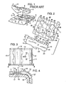
- FIG. 1 is a perspective view of the prior art teaching of Patent 4,716,666;
- FIG. 2 is a perspective, exploded view of the elements of the four point embodiment of the instant invention;
- FIG. 3 is a top plan view of the assembly of FIG. 4;
- FIG. 4 is a fragmentary side elevational view of the inventive assembly as applied to the corner of a bucket as would be seen along the sight line 4-4 applied to FIG. 3;
- FIG. 5 is a perspective, exploded view of a modified form of the four point invention with the assembled base element shown in dashed line;
- FIG. 5A is a schematic representation of the showings in FIGS. 2 and 5 interrelated to show corresponding dovetail segments;
- FIG. 6 is a top plan view of a modified form of the invention seen in FIG. 5; and
- FIG. 7 is a sectional view seen along the sight line 7-7 applied to FIG. 6;
- FIG. 8 is a schematic top plan view of a series of wear assemblies to illustrate alternative four point constructions;
- FIG. 9 is a schematic top plan view of the construction of FIG. 2, illustrating disassembly;
- FIG. 9A is a schematic top plan view of the construction of FIG. 6, illustrating disassembly thereof;
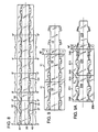
- FIG. 10 is a view similar to FIG. 8 but with the upper and lower sides transposed approximately one-third period to illustrate the three-point construction and the method of the invention;
- FIG. 11 is a top plan view of the base element as would be developed by cutting along the
lines - FIG. 11A is a top plan view of the base element as would be developed by cutting along the
lines - FIG. 13 is an end elevational view of the assembly of each of FIGS. 12 and 14;
- FIG. 14 is a top plan view of a modified form of the three point invention;
- FIG. 15 is an exploded top plan view of the three point inventive assembly;
- FIGS. 16-18 are exploded top plan views of the FIG. 14 assembly in the process of assembly;
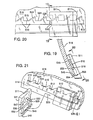
- FIG. 19 is a fragmentary side elevational view of a further modification of the three point invention useful as a cutting edge for a mold board;
- FIG. 20 is a fragmentary front elevational view of the assembly of FIG. 19; and
- FIG. 21 is a fragmentary exploded plan view of the elements of FIGS. 19 and 20 showing the mode of assembly.
- In the illustration given and with reference first to FIG. 1 which is entitled PRIOR ART, the symbol A designates the base element as seen in Patent RE 33,454 and the symbol B designates the wear element -- in this case a runner for the underside of a dragline bucket. The arrow designated C shows the path through which the element B is moved in being installed on the base element A, i.e., it is first moved upwardly into general co-planar relation and thereafter slid rearwardly so as to engage the two pairs of mating dovetails, D and E on element A and D' and E' on element B. The two pairs of dovetail elements are separated by a notch F.
- Now referring to FIG. 2 which illustrates the assembly of the instant invention, the
numeral 10 designates generally a base element while thenumeral 11 designates generally the wear element. In the illustration given, thebase element 10 includes a generally plate-like body 12 which is relatively elongated to provideend walls sidewalls body surface 17 is the inner surface which normally would be secured to the wearable part of a structure such as thecorner portion 18 of a bucket (see FIG. 4) or other structure 318 (see FIG. 13). The outer surface opposite to the attachedsurface 17 can be seen only in FIG. 4 and is designated 19 and constitutes the surface in confronting relation to thewear element 11. - The
wear element 11 has corresponding body, walls and surface parts -- designated by the same numerals, but with the addition of a prime ('). Thus, in FIG. 3, the body of thewear element 11 is 12', the end walls 13' and 14' and thesidewalls 15' and 16'. The inner surface 17' (see FIG. 4) is the surface confronting thebase element 10 while the outer surface 19' is the one engageable with abrasive material. - Still referring to the
base element 10 of FIG. 2, it will be noted that the body is equipped with integral transversely extending flanges as at 20, 21, 22 and 23 separated by relatively longitudinallyelongated notches - Illustrative of the dovetail surfaces is the outer wall or
surface 26 of theflange portion 22 in the base element 10 (see the central right hand portion of FIG. 2). When thewear element 11 is moved into engagement with thebase element 10 -- as illustrated by thecurved arrows 27 in FIG. 2 -- theflange 22 is received within thenotch 28. Then, when thewear element 11 is moved in the direction of thearrow 29, thedovetail surface 26 engages amating surface 30 in thewear element 11. Normally, theelements arrow 29 -- which tends to seat the dovetail surfaces 26, 30 more firmly against each other. More properly, such movement includes the seating engagement of the dovetail surface 31 (the mirror image of the dovetail surface 30) against the dovetail surface provided at the extremity of theflange 20; and in similar fashion, thedovetail surface 32 on thewear element 11 is seated on thedovetail surface 33 on theflange 23 of thebase element 10 and, in like fashion, thedovetail surface 34 is seated against the dovetail at the extremity of theflange 21 on thebase element 10. - We have found it advantageous to incline the
surfaces longitudinal center line 35 of thewear element 11. It is to be understood that the mating dovetail surfaces as at 26, 33, etc. on the base element are similarly inclined to the longitudinal center line (not shown) of thebase element 10. In some instances, we have found it to be further advantageous to alter somewhat the angle included between the centerline and dovetail surfaces to the range of about 10° to about 20° to insure better fits and easier release of the wear element. - Also assisting in developing better fits are the provision of
rails 11a (see FIG. 4) on the surface of the wear element confronting thebase element 10. These also can be seen in perspective in FIG. 1 adjacent the outstanding walls G and H and are designated by the symbol I. - The operation described thus far is very much like that achieved through the practice of the invention in Patent RE 33,454. To obtain the advantageous reversibility of the instant invention, we provide additional dovetail surfaces as at 36, 37 just to the right of the
transverse centerline 40 in FIG. 2 and as at 38 and 39 at the left of thewear element 11. It will also be noted that the dovetail surfaces are symmetrical about thetransverse center line 40 as they also are about thelongitudinal center line 35. Therefore, as thewear element 11 is rotated 180°, it would have the same appearance as that shown in FIG. 2 but with thedovetail surface 39 now being in the place of thedovetail surface 30, thedovetail surface 37 occupying the position of thedovetail surface 32, etc. - The dovetail surfaces in the
wear element 11 are provided by outstanding wall portions as at 41 and 42 in a fashion similar to that provided at G and H in FIG. 1 relative to the prior art. More particularly, the surface remote from that being abraded is equipped with transversely-spaced, integral outstanding portions which provide confronting walls carrying the various dovetails. These confronting walls are mirror images and spaced equally away from thelongitudinal center line 35. These confronting walls are equipped with two pairs of longitudinally spaced, substantially identical, transversely aligned notches intermediate the ends of thewear element 11. For example, one pair of notches is designated 28, 43 and theother pair - It will be seen that each notch is flanked at both longitudinal ends thereof by a dovetail surface segment of the opposed or confronting wall providing the same -- with each of the segmental flanking surfaces being convergently related to its longitudinal center line in proceeding away from its associated notch. This is illustrated by considering the dovetail surfaces 30, 36 as the segments referred to in connection with the
notch 28 and thecenter line 35. The same applies to thesegments notch 44, thesegments notch 45 and thesegments - The reversibility of the
wear element 11 relative to thebase element 10 not only is advantageous in the case of left and right mountings as in FIG. 4 where the body 12' is extended transversely of the length of the dovetail along one sidewall to go around a corner as at 12'' but also in the case of wear elements in general. Where the wear elements are flat but subjected to abrasive forces in only one longitudinal direction, wear normally occurs more at the lead portion than the trailing portion. Therefore, switching the wear element end for end effectively extends the life thereof. In the case of the right and left hand elements of the character seen in FIGS. 3 and 4, the reversible feature is especially advantageous because these normally are quite extensive and ponderous, sometimes necessitating an integral eye as at 46 to lift the same into position on the associatedbucket 18. - An alternative form of the invention can be seen in FIG. 5 which is advantageously employed where the length of the wear element is a restriction. This is achieved in the
wear element 111 of FIG. 5 by the elimination of one pair of notches, utilizing only thenotches walls walls longitudinal center line 135. These are provided by upstanding integral portions as at 141 and 142. Further, and again as in the instance of the showing in FIG. 2, the confrontingwalls - Again, there are four pairs of dovetail surfaces but here the arrangement is somewhat different. The arrangement of the dovetail surfaces is the same in the respect that flanking the
notch 128 are thesurfaces surfaces notch 28 in FIG. 2. Also in proceeding to the left, a further dovetail surface orwall segment 132 extends to the left of thesegment 136 just as thesurface 32 extends to the left of thesurface 36 in FIG. 2. However, thesegment 38 of FIG. 2 has been relocated from the left hand end to the right hand end as at 138 in FIG. 5. More particularly, theopposed sidewalls - Common to both constructions is the fact that each notch is flanked at both longitudinal ends by a segment of the confronting wall with each of the flanking segments being convergently related to the longitudinal center line in proceeding away from the associated notch. Further, each confronting wall remote from the notch has two additional segments for cooperation with the flanking segments in reversibly mounting the body on the
base element - The notches and segments are constructed as having approximately the same length with the first of the additional segments being spaced approximately two lengths from a first of the flanking segments and the second of the additional segments being spaced approximately two lengths from the second of the flanking segments with the first flanking and additional segments being parallel and the second and additional segments being parallel.
- The foregoing can be appreciated from a consideration of FIG. 5A which is a schematic top plan view of the showings in FIGS. 2 and 5 arranged to show corresponding elements, viz., the
notches segments segments additional segments segments segment 132 cooperates with, i.e., is parallel to, thesegment 130 and is spaced twolengths 1 therefrom. In the same fashion, theadditional segment 138 is related to the flankingsegment 136. Thus it will be seen relative to the showing in FIG. 5 that the additional segments are on opposite sides of thenotch 128. - Still referring to FIG. 5A and in the case of the schematic representation of FIG. 2, the flanking segments are 36 and 30 with the additional segments being 38 and 32. It will be noted that the
segment 38 is spaced two lengths from thesegment 36 and is parallel thereto while thesegment 32 is spaced two lengths from thesegment 30 and again is parallel thereto. - It may be easier to understand the bi-directional dovetail constructions and features by noting that the variations are based on a repetitive pattern as seen in FIG. 8. For instance, one gets the base/runner combination of FIG. 2 if the FIG. 8 showing is cut along the section lines 2'-2' and 2''-2''. One gets the base/runner combination of FIG. 5 if one cuts at 5'-5' and 5''-5''. One gets the base/runner combination of FIG. 6 if one cuts at 6'-6'-6''-6''. In all cases one gets a base/runner combination that is reversible. One can choose to cut where necessary to obtain specific objectives such as an assembly with dovetails shifted towards the front, towards the rear, or an assembly that is more compact when individual mounting is permissible (as opposed to serial mounting).
- In the case of the embodiment of FIG. 2, it is possible to arrange the
wear elements 11 in a continuous series -- as in a wear runner for a dragline bucket, a lining for an ore chute, etc., with the end of one wear element abutting the other -- and still provide the necessary sliding movement for removal when the same are removed serially. This is because the base 10 in FIG. 9 allows thewear element 11 to move the necessary distance M forward to disengage without blocking its movement with any necessary placement of dovetails of thebase 10. However, to serially employ the embodiment of FIG. 5, end projections are added as at 249 and 250 on thewear element 211 of FIGS. 6 and 7 for movement relative to thebase element 210. FIG. 9A shows this version with end projections and the movement M' needed to disengage dovetails and remove the wear element. - First, it should be appreciated that FIG.8 on the four point embodiment shows a repeating pattern for the base and wear elements which can be cut in any of a various number of places and still be a useable base runner assembly. However, there are other ways to cut the continuous segment. FIG. 10 shows the first step -- that of shifting one
outstanding wall 442 longitudinally relative to theother wall 441. This develops an offset J not present in the four point embodiment. - FIGS. 10, 11 and 11A will be referred to later after the details of the three point embodiment have been described. Now referring to FIG. 12 which illustrates the three-point assembly of the instant invention, the numeral 310 designates generally a base element while the numeral 311 designates generally the wear element. In the illustration given, the
base element 310 includes a generally plate-like body 312 which is relatively elongated to provideend walls sidewalls 315, 316. One body surface 317 (see FIG. 13) is the surface which normally would be secured to the wearable part of astructure 18. - The surface opposite to the attached
surface 317 can be seen only in FIG. 13 and is designated 319 and constitutes the surface in confronting relation to thewearable element 311. As in the case of FIG. 2, the body, wall and surface parts of the wear element are designated by the same numerals as those of the base element but with the addition of a prime ('), viz., 312'-317' and 319' or 412'-417' and 419'. - Still referring to the
base element 310 of FIG. 12, it will be noted that the body sidewall 315 is equipped with integral transversely extending flanges as at 322 and 323 separated by a relatively longitudinally elongated recess 324. The extremities of theflanges 322, 323 are shaped to provide divergent/convergent dovetail surfaces. - Another
flange 320 extends from theopposite body sidewall 316 and its extremity is also shaped to provide a divergent/convergent dovetail surface.Flange 320 is transversely aligned with the recess 324 -- so thatflange 320 is intermediate the length of thebody 312 while theflanges 322, 323 are adjacent the ends thereof. An important difference in the FIG. 12 showing from that of FIG. 2 is that there is only one flange extending transversely from thesidewall 316. In other words, there is no counterpart for theflange 21. Each of the flanges has an outer convergent/divergent dovetail surface. - Illustrative of the dovetail surfaces is the outer wall or
surface 326 of theflange portion 322 in thebase element 310 or 410 (see also the upper right portions of FIGS. 14 and 15). The showing in FIGS. 14 and 15 differs from that of FIG. 12 in that therecess 424 is much shorter than the recess 324, and theflange 420 is shorter than theflange 320. - The embodiment of FIGS. 14 and 15 permits both the same and a different type of mounting of the
wear element 411 on thebase element 410 from that illustrated in the prior art of FIG. 1. There, the notch F is aligned with the dovetail E, the wearable element B moved into engagement with the stationary base A and then moved rearwardly as indicated by the arrow C. The normal material flow is from right to left in the FIG. 1 illustration. - For mounting of the
wear element 411 on thebase element 410notches notches 28, 43 are employed in FIG. 1. The description of FIGS. 14, 15 applies also to FIG. 12 but certain reference numerals have been omitted in FIG. 12 for clarity. Thenotches outstanding sidewall portions wearable element 411 so that thenotch 428 is aligned with theflange 422 and thenotch 443 is aligned with the rear end of theflange 420, thewear element 411 can be mounted on thebase element 410. Thereafter thewearable element 411 is slid rearwardly (to the left in FIG. 15) alongcenterline 435 so as to bring the various dovetail surfaces into mating engagement. Again, we use the term rearwardly in the context of the direction of normal material flow -- designated in FIG. 15 by thearrow 429. This results in increasing seating engagement between the dovetail surfaces on thewear element 411 and thebase element 410. In this engagement thedovetail surface 430 mates with thedovetail surface 426 on thebase element 410. Further, thedovetail surface 432 mates with theflange dovetail surface 433 and thedovetail surface 434 mates with thedovetail surface 451 onflange 420. - Also, the embodiment of FIGS. 14 and 15 can be employed to mount the
wear element 411 on thebase element 410 without utilizing notches as in the prior art as seen in the following alternative. - This alternative action of mounting the
wear element 411 on thestationary base element 410 is illustrated in the sequence of views FIGS. 16-18. In FIG. 16, for example, it will be seen that thewear element 411 is oriented so as to have itslongitudinal center line 435a at a minor acute angle to thecenter line 435 of thebase element 410. - Then in FIG. 17, the
wear element 411 is moved rearwardly onto thebase element 410 in the direction of thearrow 429 and also the direction of normal material flow. Then thewear element 411 is rotated (clockwise as shown in FIG. 17) to bring thecenter lines wear element 411 to the left as indicated in FIG. 18 along thecenter lines - The dovetail surfaces on the
base element 410 can be seen most clearly at the left hand end of FIG. 18. There, the numeral 433 designates the dovetail surface on theflange 423 -- theflange 423 being identical to the flange 323 of FIG. 12, and theflange 422 carrying thesurface 426 is identical to theflange 322. Projecting from theopposite sidewall 416 is theflange 420 which, at its extremity, carries thedovetail surface 451. - Cooperating with these surfaces are confronting surfaces on the
wear element 411. In theoutstanding wall portion 441 -- see the right hand side of FIG. 15 -- thesurface 430 engages thesurface 426, thesurface 432 engages thesurface 433 and thesurface 434 engages thesurface 451. So thefirst wall 447 has a pair of longitudinally spaced apart dovetailsurfaces single dovetail surface 434 which is inclined at a negative or reverse angle to thecenter line 435 and is positioned intermediate the adjacent ends of the pair of dovetail surfaces, 430, 432 on the first opposingwall 447. - In FIG. 12, by providing the longer recess 324 (versus the
shorter recess 424 of FIG. 14) and the longer flange 320 (versus the flange 420) we are able to make thedovetail surface 351 approximately equal to the sum of the dovetail surfaces 326, 333. In contrast, thedovetail surface 451 in FIG. 15 is approximately the same longitudinal extent as each of the pair ofsurfaces - For the purpose of enabling the
wear element walls - To achieve the dovetail surface engagement upon reverse positioning of the
wear element dovetail surface 434 and the pair ofsurfaces surfaces - It will be noted that the dovetail surfaces 430, 432 and the reverse-
operation corresponding surfaces notch notch 443 is immediately rearward of thedovetail surface 434 when one front wall is positioned forwardly and, when theelement 411 is rotated 180°, thesingle dovetail surface 436 is immediately forward of thenotch 428. - The invention finds advantageous application to wear elements in earth working such as the
mold board 518 of FIGS. 19-21. There, it is most desirable to provide a sharp bottom cutting edge and this is achieved by installing on moldboard 518 a plurality of wearable elements in side-by-side relation as at 511 in FIG. 20. Again, thewear element 511 has side and end walls and top and bottom surfaces -- designations omitted for clarity. - For this purpose, the
mold board 518 is equipped with a plurality ofbase elements 510 in horizontal side-by-side relation. Again, eachbase element 510 includes a generally plate-like body 512 (see FIG. 21) which is generally elongated to provide end walls, sidewalls, and top and bottom surfaces as in the previous embodiments of the invention. One base element sidewall 515 (positioned upwardly in FIG. 21) has generally the contour of the previously-described embodiments, viz., convergent/divergent dovetail surfaces other sidewall surface 516 is not dovetailed but has a planar wall which merely confronts aninterior shoulder 552 on thewear element 511. The other dovetail engagement of the wear element is achieved with themoldboard 518 as at 553 -- see the lower portion of FIG. 19. - The connection of the
wear element 511 to the base element-equippedmoldboard 518 can be best appreciated from a consideration of FIG. 21 -- particularly, the perspective view of thewear element 511 shown in the process of installation along theline 529 which is parallel to the longitudinal centerline 535. - First as seen in the lower left portion of FIG. 19, the moldboard has a beveled bottom edge as at 554 which is parallel to the ground and which may be equipped with bolted on cutting edges. This
edge 554, effect, provides a dovetail surface which mates with thestraight dovetail surface 548 provided on thewear element 511 -- see the lower right portion of the separated element in FIG. 21. In other words, the dovetail-providingsurface 548 is not divergent/convergent as in the other embodiments of the invention. However, the wear element has outstanding wall portions as at 541 and 542. Thewall portion 541 has awall 547 which is equipped with the divergent/convergent surfaces notch 528 -- as in the previous embodiments. Thewalls wear elements 511. - By longitudinal centerline, reference is again to the direction of movement of the wear element when it is installed. This is illustrated by the arrow segment designated 529 in FIG. 21. Depending upon the object of the designer, the longer dimension of the wear element may be either in the direction of movement for installation or transverse thereto.
- For installation, the flange-like
outstanding wall portion 542 at the bottom of thewear element 511 is hooked under themoldboard bottom wall 554 with thenotch 528 aligned with thedovetail surface 533. Thewearable element 511 is then pivoted to place thedovetail surface 533 in thenotch 528 and thereafter thewear element 511 is slid to the right (as depicted in FIG. 21). When thewear elements 511 are assembled side-by-side, they serve to lock each other with the most outboard wear elements being locked in place by bolts or welds. Because of the dovetails being in only one of the upstanding walls, the dovetail angles do not have to be at the same convergence/divergence which relieves the need for exact tolerances. - In the practice of the invention, a variety of dovetail arrangements are possible while still following the basic teaching of the invention. Focusing on the wear element and, more particularly, the
outstanding wall portions surfaces 30, 32 (FIG. 8) or 430, 432 (FIG. 10). These are advantageously arranged at a positive angle to thelongitudinal centerlines second wall portion surface first wall portion surface - As just pointed out with reference to the mold board attachment (FIGS. 19-21) this confronting surface may be a bevel or
straight dovetail surface 548. When the confrontingsurface 434 is arranged at a negative angle with respect to thecenterline 435 of FIG. 10, it provides the third surface of the three point embodiment (see FIG. 15 also). - By flanking the
surface 434 withsurfaces centerline 435 and providing the counterpartnegative angle surface 436 between thesurfaces - This three point repeating configuration can be adjusted to obtain stackability, viz., serial mounting as in FIGS. 9 and 9A. This is achieved by elongating the base element as at 610 in FIG. 10 and adding
partial notches - Cutting the repeating pattern to develop the base element 710 (see the left hand portion of FIG. 10) permits the achievement of the four point embodiment. This
wear element 711 is seen in FIG. 10 and corresponds generally to the showing of thewear element 211 of FIG. 6. However, the notches in opposing walls are not aligned, but offset. In FIG. 6, there is a zero offset while in FIG. 11 the offset is 1/3 a period. A period is the distance between any two similar or corresponding points, i.e., between the centers of two adjacent notches, the peaks of adjacent dovetails, etc. This can be appreciated from the symbol J applied to the left hand portion of FIG. 10 and this may extend up to 1/2 a period. - This offset J can be controlled depending upon situation and function desired. This repeating pattern can then be cut at an opportune place to provide a base/wear element combination that is both stackable and reversible as well as providing three point, four point and multiple point contact.
Claims (14)
- A replaceable wear element (11, 411, 511) for installation on the wearable part (18, 518) of a structure engageable with abrasive material comprising:
a unitary relatively elongated, generally rectangular plate-like body (12', 412') having end walls (13', 413', 14', 414'), sidewalls (15', 415', 16', 416') and top and bottom surfaces (17', 417', 19', 419'), one of said surfaces (19', 419') being adapted to engage said abrasive material,
the other (17', 417') of said top and bottom surfaces being adapted to be positioned in confronting relation to said wearable part by movement generally along its longitudinal centerline (35, 435, 535),
said other surface (17', 417') adjacent both sidewalls (15', 415', 16', 416') being equipped with transversely-spaced, integral portions (41, 441, 42, 442, 541, 542) providing opposing walls (47, 447, 48, 448, 547, 548),
a first (47, 447, 547) of said opposing walls having a pair of longitudinally spaced apart dovetail surfaces (30, 430, 530, 32, 432, 532) inclined at a positive angle to said centerline (35, 435, 535), the improvement characterized by
the second (48, 148, 548) of said opposing walls having a dovetail surface (37, 434, 548) positioned intermediate the adjacent ends of said first opposing wall pair of dovetail surfaces (30, 430, 530, 32, 432, 532). - The wear element of claim 1 in which said second opposing wall dovetail surface (37, 434) is inclined at an angle to said centerline (35, 435).
- The wear element of claim 2 in which
a pair of substantially identical notches (28, 43, 128, 143) are provided in said confronting walls (47, 48, 147, 148) intermediate the ends (13', 14') of said body (12'),
each notch being flanked at both longitudinal ends thereof by a segmental dovetail surface (30, 36, 31, 37, 130, 137) of said confronting wall, each of said flanking surfaces being convergently related to said longitudinal centerline (35, 135) in proceeding away from its associated notch,
each of said confronting walls having two additional segmental dovetail surfaces (32, 38, 34, 39, 132, 138, 134, 139) for cooperation with said flanking segments in reversibly mounting said body on said wearable part,
a first (32, 34, 132, 134) of said additional segmental surfaces being spaced from a first (30, 31, 130, 131) of said segmental flanking surfaces and the second (38, 39, 138, 139) of said additional segmental surfaces being spaced from the second (36, 37, 136, 137) of said segmental flanking surfaces with said first flanking surfaces (30, 31) being parallel to said additional segmental surfaces (32, 34) and second flanking surfces (36, 37) being parallel to said additional segmental surfaces (38, 39). - The wear element of claim 3 in which said body has a single engagement notch (128, 143) in each wall, said segmental additional surfaces being on opposite sides of said notch (128).
- The wear element of claim 3 in which said body has a second engagement notch (44, 45) in each wall, said additional segmental surfaces (32, 38) both being on the same side of the first-mentioned notch (28).
- The wear element of claim 1 in combination with a base element (10, 110, 410, 510), said base element being securable to said wearable part (18, 518) of a structure engageable with abrasive material, said base element having dovetail surfaces (26, 33, 426, 433, 526, 533) engaging said pair of longitudinally spaced apart dovetail surfaces (30, 32, 430, 432, 530, 532) in said first opposing wall.
- The wear element of claim 1 in which said second opposing wall is a single dovetail surface (548) extending parallel to said centerline (535).
- The wear element of claim 1 in which said second opposing wall (448) includes a single dovetail surface (434) inclined at a negative angle to said centerline (435).
- The wear element of claim 8 in which said body has a forward end (413') positioned first in the path of material flow, a notch (428) provided in said first wall (447) adjacent the rear end of the forward one (430) of said pair of dovetail surfaces, and a notch (443) in said second wall (448) adjacent the rear of said single dovetail surface (434).
- The wear element of claim 8 in which said first opposing wall (447) is equipped with a single dovetail surface (436) positioned between said pair of longitudinally spaced apart dovetail surfaces (430, 432) and inclined at the same angle as said second wall single dovetail surface (434), said second opposing wall (448) being equipped with a pair of dovetail surfaces flanking said second wall single dovetail surface (434) and inclined at the same angle as said first wall pair (430, 432) of longitudinally spaced apart dovetail surfaces, said first wall (447) corresponding to said second wall (448) when rotated 180° whereby said wear element is reversely mountable on a mating base element.
- In a method of designing a dovetail connection between a relatively elongated base element mountable on a surface subject to abrasive wear and a relatively elongated wear element engageable with abrasive material where said wear element is mountable on said base element by movement generally along the longitudinal centerlines of said elements, the steps of:
developing a repeating pattern of dovetail surfaces in each of a pair of opposing walls in each of said elements to provide two transversely spaced sets of confronting walls,
including in one of said confronting wall sets at least two longitudinally spaced apart dovetail segments inclined at a positive angle to said centerlines, and separated by a transversely-extending notch in both element confronting walls, and
terminating the elements by cutting with longitudinally spaced transverse planes at least beyond the opposite ends of said two segments. - The method of claim 11 in which there is included in the other of said confronting wall sets at least one dovetail segment positioned intermediate the adjacent ends of said two longitudinal spaced dovetail segments, the notches in said sets being generally transversely aligned.
- The method of claim 11 in which there is included in the other of said confronting wall sets at least one dovetail segment positioned intermediate the adjacent ends of said two longitudinal spaced dovetail segments, the corresponding points in said sets being longitudinally offset up to one-half period where a period is the longitudinal distance between corresponding points in the same wall set.
- A replaceable wear element for installation on the wearable part of a structure engageable with abrasive material comprising
a unitary relatively elongated, generally rectangular plate-like body having end and sidewalls and top and bottom surfaces, one of said surfaces being adapted to engage said abrasive material,
the other of said top and bottom surfaces being adapted to be positioned in confronting relation to said wearable part by movement along its longitudinal centerline,
said other surface adjacent both sidewalls being equipped with transversely-spaced, integral outstanding portions providing confronting walls, said confronting walls being mirror images and spaced equally away from said longitudinal centerline,
a pair of substantially identical, transversely aligned notches in said confronting walls intermediate the ends of said body,
each notch being flanked at both longitudinal ends thereof by a segment of said confronting wall, each of said flanking segments being convergently related to said longitudinal centerline in proceeding away from its associated notch,
each confronting wall remote from said notch having two longitudinally spaced apart additional segments for cooperation with said flanking segments in reversibly mounting said body on said wearable part,
a first of said additional segments being spaced from a first of said flanking segments and the second of said additional segments being spaced from the second of said flanking segments with said first flanking and additional segments being parallel and second flanking and additional segments being parallel, and
each of said confronting wall segments being sloped transversely toward said one surface and its adjacent side wall.
Applications Claiming Priority (6)
| Application Number | Priority Date | Filing Date | Title |
|---|---|---|---|
| US478359 | 1990-02-12 | ||
| US07/478,359 US5005304A (en) | 1990-02-12 | 1990-02-12 | Replaceable wear element |
| US07/528,087 US4995176A (en) | 1990-05-24 | 1990-05-24 | Replaceable wear element, assembly and method |
| US528087 | 1990-05-24 | ||
| US07/627,509 US5063695A (en) | 1990-02-12 | 1990-12-20 | Replaceable wear element and method |
| US627509 | 1990-12-20 |
Publications (3)
| Publication Number | Publication Date |
|---|---|
| EP0442449A2 true EP0442449A2 (en) | 1991-08-21 |
| EP0442449A3 EP0442449A3 (en) | 1992-03-04 |
| EP0442449B1 EP0442449B1 (en) | 1996-04-24 |
Family
ID=27413442
Family Applications (1)
| Application Number | Title | Priority Date | Filing Date |
|---|---|---|---|
| EP91101959A Expired - Lifetime EP0442449B1 (en) | 1990-02-12 | 1991-02-12 | Replaceable wear element |
Country Status (17)
| Country | Link |
|---|---|
| EP (1) | EP0442449B1 (en) |
| JP (1) | JPH0739678B2 (en) |
| KR (1) | KR960009733B1 (en) |
| AT (1) | ATE137283T1 (en) |
| AU (1) | AU634344B2 (en) |
| BR (1) | BR9100567A (en) |
| CA (1) | CA2036118C (en) |
| DE (2) | DE442449T1 (en) |
| ES (1) | ES2033625T3 (en) |
| FI (1) | FI97249C (en) |
| GR (2) | GR920300100T1 (en) |
| HK (1) | HK1005600A1 (en) |
| MY (1) | MY106068A (en) |
| NO (2) | NO302963B1 (en) |
| NZ (1) | NZ237065A (en) |
| PH (1) | PH27540A (en) |
| PT (1) | PT96744B (en) |
Cited By (3)
| Publication number | Priority date | Publication date | Assignee | Title |
|---|---|---|---|---|
| AU659951B2 (en) * | 1992-11-18 | 1995-06-01 | Dural International Pty. Ltd. | Wear resistant blocks and associated retaining insert plates |
| WO2000042834A1 (en) * | 1999-01-22 | 2000-07-27 | Kverneland Klepp As | Replaceable wear part for soil-engaging tool |
| WO2017083264A1 (en) * | 2015-11-09 | 2017-05-18 | Caterpillar Inc. | Wear member |
Families Citing this family (4)
| Publication number | Priority date | Publication date | Assignee | Title |
|---|---|---|---|---|
| US5553409A (en) * | 1995-08-22 | 1996-09-10 | Foothills Steel Foundry Ltd. | Shroud anchor system |
| JP5943038B2 (en) * | 2014-06-20 | 2016-06-29 | コベルコ建機株式会社 | Tooth board structure |
| US9670648B2 (en) | 2015-08-10 | 2017-06-06 | Caterpillar Inc. | Replaceable tip systems for a tine |
| US11905686B2 (en) | 2021-07-28 | 2024-02-20 | Caterpillar Inc. | Replaceable wear plate |
Citations (5)
| Publication number | Priority date | Publication date | Assignee | Title |
|---|---|---|---|---|
| US2896345A (en) * | 1954-07-23 | 1959-07-28 | Electric Steel Foundry Co | Tooth assembly |
| US3500562A (en) * | 1967-04-28 | 1970-03-17 | Richard B Reinhard | Tooth arrangement for alternate digging and scooping |
| US3995384A (en) * | 1974-11-25 | 1976-12-07 | John F. Duncan | Edge bit structure for implement blade |
| US4457380A (en) * | 1981-06-03 | 1984-07-03 | Curry John N | Blades for earth moving machines |
| EP0262856A1 (en) * | 1986-09-29 | 1988-04-06 | Esco Corporation | Wear runner for excavating bucket |
Family Cites Families (1)
| Publication number | Priority date | Publication date | Assignee | Title |
|---|---|---|---|---|
| US3202226A (en) * | 1963-11-13 | 1965-08-24 | Cyril W Carson | Replaceable cutting edge for a blade assembly |
-
1991
- 1991-02-08 BR BR919100567A patent/BR9100567A/en not_active IP Right Cessation
- 1991-02-11 MY MYPI91000220A patent/MY106068A/en unknown
- 1991-02-11 CA CA002036118A patent/CA2036118C/en not_active Expired - Lifetime
- 1991-02-11 NZ NZ237065A patent/NZ237065A/en unknown
- 1991-02-11 PT PT96744A patent/PT96744B/en not_active IP Right Cessation
- 1991-02-11 NO NO910531A patent/NO302963B1/en unknown
- 1991-02-11 FI FI910648A patent/FI97249C/en not_active IP Right Cessation
- 1991-02-11 NO NO91910531A patent/NO910531L/en unknown
- 1991-02-12 KR KR1019910002320A patent/KR960009733B1/en not_active IP Right Cessation
- 1991-02-12 EP EP91101959A patent/EP0442449B1/en not_active Expired - Lifetime
- 1991-02-12 JP JP3038909A patent/JPH0739678B2/en not_active Expired - Fee Related
- 1991-02-12 ES ES91101959T patent/ES2033625T3/en not_active Expired - Lifetime
- 1991-02-12 AT AT91101959T patent/ATE137283T1/en active
- 1991-02-12 PH PH41977A patent/PH27540A/en unknown
- 1991-02-12 DE DE199191101959T patent/DE442449T1/en active Pending
- 1991-02-12 DE DE69118942T patent/DE69118942T2/en not_active Expired - Lifetime
- 1991-02-12 AU AU70973/91A patent/AU634344B2/en not_active Expired
-
1993
- 1993-02-17 GR GR920300100T patent/GR920300100T1/en unknown
-
1996
- 1996-04-25 GR GR960400475T patent/GR3019755T3/en unknown
-
1998
- 1998-06-03 HK HK98104777A patent/HK1005600A1/en not_active IP Right Cessation
Patent Citations (5)
| Publication number | Priority date | Publication date | Assignee | Title |
|---|---|---|---|---|
| US2896345A (en) * | 1954-07-23 | 1959-07-28 | Electric Steel Foundry Co | Tooth assembly |
| US3500562A (en) * | 1967-04-28 | 1970-03-17 | Richard B Reinhard | Tooth arrangement for alternate digging and scooping |
| US3995384A (en) * | 1974-11-25 | 1976-12-07 | John F. Duncan | Edge bit structure for implement blade |
| US4457380A (en) * | 1981-06-03 | 1984-07-03 | Curry John N | Blades for earth moving machines |
| EP0262856A1 (en) * | 1986-09-29 | 1988-04-06 | Esco Corporation | Wear runner for excavating bucket |
Cited By (5)
| Publication number | Priority date | Publication date | Assignee | Title |
|---|---|---|---|---|
| AU659951B2 (en) * | 1992-11-18 | 1995-06-01 | Dural International Pty. Ltd. | Wear resistant blocks and associated retaining insert plates |
| WO2000042834A1 (en) * | 1999-01-22 | 2000-07-27 | Kverneland Klepp As | Replaceable wear part for soil-engaging tool |
| WO2017083264A1 (en) * | 2015-11-09 | 2017-05-18 | Caterpillar Inc. | Wear member |
| US9863119B2 (en) | 2015-11-09 | 2018-01-09 | Caterpillar Inc. | Wear member |
| RU2722637C2 (en) * | 2015-11-09 | 2020-06-02 | Кейтерпиллар Инк. | Wearing element |
Also Published As
| Publication number | Publication date |
|---|---|
| DE442449T1 (en) | 1992-11-26 |
| AU634344B2 (en) | 1993-02-18 |
| NZ237065A (en) | 1992-11-25 |
| HK1005600A1 (en) | 1999-01-15 |
| AU7097391A (en) | 1991-08-15 |
| FI97249B (en) | 1996-07-31 |
| NO910531D0 (en) | 1991-02-11 |
| DE69118942D1 (en) | 1996-05-30 |
| ES2033625T3 (en) | 1996-07-16 |
| GR920300100T1 (en) | 1993-02-17 |
| BR9100567A (en) | 1991-10-29 |
| JPH0739678B2 (en) | 1995-05-01 |
| MY106068A (en) | 1995-03-31 |
| EP0442449B1 (en) | 1996-04-24 |
| GR3019755T3 (en) | 1996-07-31 |
| PT96744B (en) | 1998-08-31 |
| FI97249C (en) | 1996-11-11 |
| KR960009733B1 (en) | 1996-07-23 |
| NO302963B1 (en) | 1998-05-11 |
| ES2033625T1 (en) | 1993-04-01 |
| FI910648A0 (en) | 1991-02-11 |
| FI910648A (en) | 1991-08-13 |
| CA2036118A1 (en) | 1991-08-13 |
| NO910531L (en) | 1991-08-13 |
| ATE137283T1 (en) | 1996-05-15 |
| JPH04213632A (en) | 1992-08-04 |
| PH27540A (en) | 1993-08-18 |
| EP0442449A3 (en) | 1992-03-04 |
| CA2036118C (en) | 1995-04-18 |
| PT96744A (en) | 1993-01-29 |
| KR910015763A (en) | 1991-09-30 |
| DE69118942T2 (en) | 1996-11-28 |
Similar Documents
| Publication | Publication Date | Title |
|---|---|---|
| US5063695A (en) | Replaceable wear element and method | |
| US5005304A (en) | Replaceable wear element | |
| US4995176A (en) | Replaceable wear element, assembly and method | |
| EP0262856B1 (en) | Wear runner for excavating bucket | |
| US5056243A (en) | Connection for elements at least one of which is subject to abrasive wear | |
| US4282665A (en) | Excavator tooth assembly | |
| US9909285B2 (en) | Shroud retention system for a work tool | |
| CA1152128A (en) | Excavating tooth assembly | |
| US4577423A (en) | Excavating tooth system | |
| US9938695B2 (en) | Shroud retention system for a work tool | |
| GB2303865A (en) | Replaceable wear runner | |
| US3202226A (en) | Replaceable cutting edge for a blade assembly | |
| CA2956142C (en) | Wear component for ground engaging tool | |
| CA2036118C (en) | Replaceable wear element and method | |
| US4457380A (en) | Blades for earth moving machines | |
| US4576239A (en) | Scarifier tooth assembly | |
| US20190376263A1 (en) | Wear member, edge and process of installation | |
| US20220356682A1 (en) | Weldless boss for attaching lips to a work implement | |
| BR112017001216B1 (en) | WEAR COMPONENT FOR GROUND CUTTING TOOL | |
| USRE33454E (en) | Wear runner for excavating bucket | |
| CN113242923B (en) | Wear resistant component and wear resistant assembly | |
| US5283965A (en) | Attachment assembly for excavation teeth | |
| EA041562B1 (en) | WEAR ELEMENT, EDGE AND INSTALLATION PROCESS | |
| AU778981B2 (en) | Locking pin for ground engaging tool components | |
| DE2452649B2 (en) | SHOVEL-SHAPED TOOL FOR MACHINES FOR EARTH WORKING |
Legal Events
| Date | Code | Title | Description |
|---|---|---|---|
| PUAI | Public reference made under article 153(3) epc to a published international application that has entered the european phase |
Free format text: ORIGINAL CODE: 0009012 |
|
| AK | Designated contracting states |
Kind code of ref document: A2 Designated state(s): AT BE CH DE DK ES FR GB GR IT LI NL SE |
|
| PUAL | Search report despatched |
Free format text: ORIGINAL CODE: 0009013 |
|
| AK | Designated contracting states |
Kind code of ref document: A3 Designated state(s): AT BE CH DE DK ES FR GB GR IT LI NL SE |
|
| ITCL | It: translation for ep claims filed |
Representative=s name: BARZANO' E ZANARDO ROMA S.P.A. |
|
| 17P | Request for examination filed |
Effective date: 19920811 |
|
| TCAT | At: translation of patent claims filed | ||
| EL | Fr: translation of claims filed | ||
| TCNL | Nl: translation of patent claims filed | ||
| DET | De: translation of patent claims | ||
| 17Q | First examination report despatched |
Effective date: 19930824 |
|
| GRAH | Despatch of communication of intention to grant a patent |
Free format text: ORIGINAL CODE: EPIDOS IGRA |
|
| GRAA | (expected) grant |
Free format text: ORIGINAL CODE: 0009210 |
|
| ITF | It: translation for a ep patent filed |
Owner name: BARZANO' E ZANARDO ROMA S.P.A. |
|
| AK | Designated contracting states |
Kind code of ref document: B1 Designated state(s): AT BE CH DE DK ES FR GB GR IT LI NL SE |
|
| PG25 | Lapsed in a contracting state [announced via postgrant information from national office to epo] |
Ref country code: DK Effective date: 19960424 |
|
| REF | Corresponds to: |
Ref document number: 137283 Country of ref document: AT Date of ref document: 19960515 Kind code of ref document: T |
|
| REG | Reference to a national code |
Ref country code: CH Ref legal event code: NV Representative=s name: KIRKER & CIE SA |
|
| REF | Corresponds to: |
Ref document number: 69118942 Country of ref document: DE Date of ref document: 19960530 |
|
| REG | Reference to a national code |
Ref country code: ES Ref legal event code: BA2A Ref document number: 2033625 Country of ref document: ES Kind code of ref document: T3 |
|
| REG | Reference to a national code |
Ref country code: GR Ref legal event code: FG4A Free format text: 3019755 |
|
| REG | Reference to a national code |
Ref country code: ES Ref legal event code: FG2A Ref document number: 2033625 Country of ref document: ES Kind code of ref document: T3 |
|
| ET | Fr: translation filed | ||
| NLR4 | Nl: receipt of corrected translation in the netherlands language at the initiative of the proprietor of the patent | ||
| PGFP | Annual fee paid to national office [announced via postgrant information from national office to epo] |
Ref country code: GR Payment date: 19961223 Year of fee payment: 7 |
|
| PGFP | Annual fee paid to national office [announced via postgrant information from national office to epo] |
Ref country code: NL Payment date: 19970120 Year of fee payment: 7 |
|
| PGFP | Annual fee paid to national office [announced via postgrant information from national office to epo] |
Ref country code: AT Payment date: 19970123 Year of fee payment: 7 |
|
| PLBE | No opposition filed within time limit |
Free format text: ORIGINAL CODE: 0009261 |
|
| STAA | Information on the status of an ep patent application or granted ep patent |
Free format text: STATUS: NO OPPOSITION FILED WITHIN TIME LIMIT |
|
| PGFP | Annual fee paid to national office [announced via postgrant information from national office to epo] |
Ref country code: BE Payment date: 19970306 Year of fee payment: 7 |
|
| 26N | No opposition filed | ||
| PGFP | Annual fee paid to national office [announced via postgrant information from national office to epo] |
Ref country code: CH Payment date: 19970422 Year of fee payment: 7 |
|
| PG25 | Lapsed in a contracting state [announced via postgrant information from national office to epo] |
Ref country code: AT Free format text: LAPSE BECAUSE OF NON-PAYMENT OF DUE FEES Effective date: 19980212 |
|
| PG25 | Lapsed in a contracting state [announced via postgrant information from national office to epo] |
Ref country code: LI Free format text: LAPSE BECAUSE OF NON-PAYMENT OF DUE FEES Effective date: 19980228 Ref country code: BE Free format text: LAPSE BECAUSE OF NON-PAYMENT OF DUE FEES Effective date: 19980228 Ref country code: CH Free format text: LAPSE BECAUSE OF NON-PAYMENT OF DUE FEES Effective date: 19980228 |
|
| BERE | Be: lapsed |
Owner name: ESCO CORP. Effective date: 19980228 |
|
| PG25 | Lapsed in a contracting state [announced via postgrant information from national office to epo] |
Ref country code: GR Free format text: LAPSE BECAUSE OF NON-PAYMENT OF DUE FEES Effective date: 19980831 |
|
| PG25 | Lapsed in a contracting state [announced via postgrant information from national office to epo] |
Ref country code: NL Free format text: LAPSE BECAUSE OF NON-PAYMENT OF DUE FEES Effective date: 19980901 |
|
| REG | Reference to a national code |
Ref country code: CH Ref legal event code: PL |
|
| NLV4 | Nl: lapsed or anulled due to non-payment of the annual fee |
Effective date: 19980901 |
|
| REG | Reference to a national code |
Ref country code: GB Ref legal event code: IF02 |
|
| PGFP | Annual fee paid to national office [announced via postgrant information from national office to epo] |
Ref country code: ES Payment date: 20100225 Year of fee payment: 20 |
|
| PGFP | Annual fee paid to national office [announced via postgrant information from national office to epo] |
Ref country code: FR Payment date: 20100303 Year of fee payment: 20 Ref country code: IT Payment date: 20100224 Year of fee payment: 20 |
|
| PGFP | Annual fee paid to national office [announced via postgrant information from national office to epo] |
Ref country code: GB Payment date: 20100224 Year of fee payment: 20 Ref country code: DE Payment date: 20100226 Year of fee payment: 20 |
|
| PGFP | Annual fee paid to national office [announced via postgrant information from national office to epo] |
Ref country code: SE Payment date: 20100226 Year of fee payment: 20 |
|
| REG | Reference to a national code |
Ref country code: DE Ref legal event code: R071 Ref document number: 69118942 Country of ref document: DE |
|
| REG | Reference to a national code |
Ref country code: GB Ref legal event code: PE20 Expiry date: 20110211 |
|
| EUG | Se: european patent has lapsed | ||
| PG25 | Lapsed in a contracting state [announced via postgrant information from national office to epo] |
Ref country code: GB Free format text: LAPSE BECAUSE OF EXPIRATION OF PROTECTION Effective date: 20110211 |
|
| REG | Reference to a national code |
Ref country code: ES Ref legal event code: FD2A Effective date: 20120510 |
|
| PG25 | Lapsed in a contracting state [announced via postgrant information from national office to epo] |
Ref country code: ES Free format text: LAPSE BECAUSE OF EXPIRATION OF PROTECTION Effective date: 20110213 |
|
| PG25 | Lapsed in a contracting state [announced via postgrant information from national office to epo] |
Ref country code: DE Free format text: LAPSE BECAUSE OF EXPIRATION OF PROTECTION Effective date: 20110212 |