EP0441810B1 - Process for placing modules on a support - Google Patents
Process for placing modules on a support Download PDFInfo
- Publication number
- EP0441810B1 EP0441810B1 EP89911775A EP89911775A EP0441810B1 EP 0441810 B1 EP0441810 B1 EP 0441810B1 EP 89911775 A EP89911775 A EP 89911775A EP 89911775 A EP89911775 A EP 89911775A EP 0441810 B1 EP0441810 B1 EP 0441810B1
- Authority
- EP
- European Patent Office
- Prior art keywords
- modules
- subregions
- plt
- module
- placement
- Prior art date
- Legal status (The legal status is an assumption and is not a legal conclusion. Google has not performed a legal analysis and makes no representation as to the accuracy of the status listed.)
- Expired - Lifetime
Links
Images

Classifications
-
- G—PHYSICS
- G06—COMPUTING; CALCULATING OR COUNTING
- G06F—ELECTRIC DIGITAL DATA PROCESSING
- G06F30/00—Computer-aided design [CAD]
- G06F30/30—Circuit design
- G06F30/39—Circuit design at the physical level
- G06F30/392—Floor-planning or layout, e.g. partitioning or placement
Abstract
Description
Die Erfindung bezieht sich auf ein Verfahren zur Plazierung von Modulen auf einem Träger unter Verwendung von einer die Abmessungen der Module enthaltenden Modulliste und einer die Verbindungen der Module enthaltenden Netzliste.The invention relates to a method for placing modules on a carrier using a module list containing the dimensions of the modules and a network list containing the connections of the modules.
Verfahren zur Plazierung von Modulen auf einem Träger z.B. von Gate-Arrays, Standardzellen, Makrozellen auf einem Chip oder von Bausteinen auf Leiterplatten, sind bekannt. Als Beispiele für den Stand der Technik wird hingewiesen auf Cheng, C.-K., Kuh, E.S.: Module placement based on resistive network optimization, IEEE Transactions on Computer-Aided Design, Band CAD-3, 1984, S. 218-225; Just, K.M., KLeinhans, J.M., Johannes, F.M., On the relative placement and the transportation problem for standard-cell layout, Design Automation Conference, 1986, S. 308-313. In diesen Literaturstellen sind Verfahren angegeben, mit deren Hilfe Module in ihrer relativen Lage zueinander zunächst auf dem Träger plaziert werden und dann ihre endgültige Lage auf dem Träger zugewiesen bekommen. Ausgangspunkt ist die Topologie der Schaltung, also z.B. ein Stromlaufplan, aus dem sich ergibt, wie eine Anzahl von Modulen miteinander verbunden sind. Aufgabe der Plazierung ist es dann, diese Module unter Berücksichtigung ihrer Verbindungen optimal auf einem Träger, z.B. einem Chip, anzuordnen. Das Plazierungsverfahren ist ausführlich in den genannten Literaturstellen beschrieben, auf die verwiesen wird.Method for placing modules on a carrier e.g. Gate arrays, standard cells, macro cells on a chip or components on printed circuit boards are known. As examples of the prior art, reference is made to Cheng, C.-K., Kuh, ES: Module placement based on resistive network optimization, IEEE Transactions on Computer-Aided Design, Volume CAD-3, 1984, pp. 218-225 ; Just, K.M., KLeinhans, J.M., Johannes, F.M., On the relative placement and the transportation problem for standard-cell layout, Design Automation Conference, 1986, pp. 308-313. In these references, methods are specified by means of which modules are first placed in their relative position to one another on the support and then assigned to their final position on the support. The starting point is the topology of the circuit, e.g. a circuit diagram showing how a number of modules are interconnected. It is then the job of placing these modules optimally on a carrier, e.g. a chip. The placement procedure is described in detail in the cited references to which reference is made.
Die bekannten Verfahren streben zunächst eine Relativplazierung der Module zueinander an. Dazu werden die Koordinaten der einzelnen Module so berechnet, daß der Schwerpunkt der Module in einem vorgegebenen Punkt, z.B. den Zentrumskoordinaten der für die Anordnung vorgesehenen Fläche der Plazierungsfläche, liegen. Die Koordinaten der Module werden durch Lösen eines Optimierungsproblems ermittelt, bei dem eine Funktion der Abstände der miteinander verbundenen Module zu einem Minimum gemacht wird. Die Lösung dieses Optimierungsproblems erfolgt unter Berücksichtigung von Nebenbedingungen, durch die erreicht wird, daß die Module möglichst gleichverteilt auf der Plazierungsfläche liegen. Die Bestimmung der endgültigen und überlappungsfreien Lage der Module erfolgt nach Abschluß der relativen Plazierung. Dabei wird die Information der Relativplazierung genutzt.The known methods initially aim to position the modules relative to one another. For this purpose, the coordinates of the individual modules are calculated in such a way that the center of gravity of the modules lies in a predetermined point, for example the center coordinates of the area of the placement area provided for the arrangement. The coordinates of the modules are determined by solving one Optimization problem determined in which a function of the spacing of the interconnected modules is made to a minimum. This optimization problem is solved taking into account secondary conditions which ensure that the modules are as evenly distributed as possible on the placement surface. The final and overlap-free position of the modules is determined after the relative placement has been completed. The information of the relative placement is used.
Die der Erfindung zugrundeliegende Aufgabe besteht darin, ein weiteres Verfahren zur Plazierung von vorgefertigten Modulen auf einem Träger anzugeben.The object on which the invention is based is to specify a further method for placing prefabricated modules on a carrier.
Diese Aufgabe wird bei einem Verfahren der eingangs angegebenen Art gemäß Patentanspruch 1 gelöst.This object is achieved in a method of the type specified at the outset according to claim 1.
Das Verfahren besteht somit aus einer Wiederholung einer Globalplazierung der Module auf einem Plazierungsgebiet und nachfolgender Partitionierung, wobei diese Schritte solange wiederholt werden, bis jedes durch Aufteilung festgelegte Teilgebiet höchstens eine vorgegebene Anzahl von Modulen enthält. Die Globalplazierung erfolgt durch Anordnung der Module in den Teilgebieten derart, daß die den Teilgebieten zugewiesenen Module mit ihren Schwerpunkten auf die Zentrums-Koordinaten dieser Teilgebiete fallen. Im Unterschied zu den bekannten Verfahren wird hierbei die Anordnung aller Moduln aller Teilgebiete simultan berechnet. Die Teilgebiete werden durch Partitionierung des Plazierungsgebietes bzw. von Teilgebieten erreicht, wobei den durch die Partitionierung erreich ten Teilgebieten eine wählbare Anzahl von Modulen zugeordnet werden und die Größe der durch die Partitionierung erreichten Teilgebiete in Abhängigkeit der zugewiesenen Module festgelegt wird.The method thus consists of repeating a global placement of the modules on a placement area and subsequent partitioning, these steps being repeated until each sub-area defined by division contains at most a predetermined number of modules. The global placement takes place by arranging the modules in the sub-areas such that the modules assigned to the sub-areas fall with their focal points on the center coordinates of these sub-areas. In contrast to the known methods, the arrangement of all modules of all sub-areas is calculated simultaneously. The sub-areas are reached by partitioning the placement area or sub-areas, with the sub-areas achieved by the partitioning being assigned a selectable number of modules and the size of the sub-areas achieved by the partitioning being determined as a function of the assigned modules.
Die Unterteilung des Plazierungsgebietes bzw. der Teilgebiete erfolgt zweckmäßigerweise durch horizontale oder vertikale Schnittlinien. Für die Zuweisung der Module zu den Teilgebieten ist dann lediglich eine Sortierung der Module nach ihren x- bzw. y-Koordinaten aus der vorherigen Globalplazierung erforderlich. Zweckmäßig ist es, wenn die Partitionierung aus einer Zweiteilung der aufzuteilenden Gebiete besteht.The subdivision of the placement area or the sub-areas is expediently carried out by horizontal or vertical Cutting lines. All that is required to assign the modules to the sub-areas is to sort the modules according to their x or y coordinates from the previous global placement. It is useful if the partitioning consists of a division of the areas to be divided.
Die Wiederholung von Globalplazierung und Partitionierung kann solange fortgeführt werden, bis in jedem Teilgebiet nur noch ein Modul angeordnet ist. Vorteilhafter ist es jedoch, wenn diese Wiederholung abgebrochen wird, wenn in jedem Teilgebiet höchstens eine vorgegebene Anzahl von Modulen, z.B. 8 Module, enthalten sind. Dann kann mit einem Optimierungsschritt die endgültige Anordnung der Module unter optimaler Flächenausnutzung auf dem Plazierungsgebiet durchgeführt werden. Dieser Schritt kann darin bestehen, daß alle möglichen Zerteilungen der Teilgebiete mit bis zu k Modulen unter Ausnutzung des Ergebnisses der Globalplazierung festgestellt werden und die dabei gefundenen Abmessungen der Teilflächen für die Plazierung eines Bausteins in einer Formfunktion zusammengefaßt werden. Dieser Schritt kann für alle derartigen Teilgebiete durchgeführt werden. Durch Addition der Formfunktionen dieser Teilgebiete können die Abmessungen aller erlaubten Modulanordnungen berechnet werden.The repetition of global placement and partitioning can be continued until only one module is arranged in each sub-area. However, it is more advantageous if this repetition is terminated if at most a predetermined number of modules, e.g. 8 modules are included. Then the final arrangement of the modules can be carried out with optimal use of space on the placement area with an optimization step. This step can consist of determining all possible subdivisions of the subareas with up to k modules using the result of the global placement and summarizing the dimensions of the subareas found for the placement of a module in a form function. This step can be carried out for all such sub-areas. By adding the shape functions of these sub-areas, the dimensions of all permitted module arrangements can be calculated.
Andere Weiterbildungen der Erfindung ergeben sich aus den Unteransprüchen.Other developments of the invention result from the subclaims.
Das erfindungsgemäße Verfahren hat den Vorteil, daß Module verschiedener Abmessungen überlappungsfrei in einer Ebene angeordnet werden können, wobei Vorgaben für die Orte eines Teils der Module berücksichtigt werden. Das Verfahren optimiert die Anordnung bezüglich einer Funktion der Abstände zwischen gegebenen Gruppen von Modulen und bezüglich der Gesamtfläche der Modulanordnung.The method according to the invention has the advantage that modules of different dimensions can be arranged in one plane without overlap, taking into account specifications for the locations of a part of the modules. The method optimizes the arrangement with respect to a function of the distances between given groups of modules and with respect to the total area of the module arrangement.
Das Verfahren dient insbesondere dem Zweck, die Plazierung der Module (Zellen, Bausteine) beim Layout-Entwurf elektrischer Schaltungen, d.h. die Umsetzung einer gegebenen Funktionsbeschreibung der Schaltung in eine ebene örtliche Anordnung durchzuführen. Dabei sind die Abmessungen der Module in einer Modulliste spezifiziert. Die Funktionsbeschreibung ist als Netzliste gegeben, in der alle Modulgruppen angegeben sind, die bei der Minimierung der Modulabstände berücksichtigt werden sollen.The method serves in particular the purpose of placing the modules (cells, building blocks) when designing electrical layouts Circuits, ie the implementation of a given functional description of the circuit in a flat local arrangement. The dimensions of the modules are specified in a module list. The functional description is given as a network list in which all module groups are specified that should be taken into account when minimizing the module spacing.
Das Verfahren ist sowohl für den Layout-Entwurf integrierter Zellenschaltungen in Standardzellen-, Makrozellen-, Gate-Array- und Sea of Gates Technologie als auch für die Plazierung von Bausteinen auf Leiterplatten geeignet.The method is suitable for the layout design of integrated cell circuits in standard cell, macro cell, gate array and sea of gates technology as well as for the placement of components on printed circuit boards.
Anhand eines Ausführungsbeispiels, das in den Figuren dargestellt ist, wird die Erfindung weiter erläutert. Es zeigen
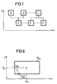
- Figur 1
- ein Beispiel für einen Stromlaufplan,
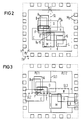
- Figur 2
- die Anordnung von Modulen im Plazierungsgebiet beim ersten Durchgang,
Figur 3- das Plazierungsgebiet mit Anordnung der Module bei einem zweiten Durchgang,
- Figur 4
- dasselbe nach einem dritten Durchgang,
- Figur 5
- die endgültige Plazierung der Module auf dem Plazierungsgebiet,
- Figur 6
- eine Erläuterung der X-,Y-Koordinaten eines Moduls,
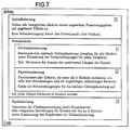
- Figur 7
- ein Ablaufdiagramm des Verfahrens.
- Figure 1
- an example of a circuit diagram,
- Figure 2
- the arrangement of modules in the placement area during the first round,
- Figure 3
- the placement area with arrangement of the modules in a second pass,
- Figure 4
- the same after a third run,
- Figure 5
- the final placement of the modules on the placement area,
- Figure 6
- an explanation of the X, Y coordinates of a module,
- Figure 7
- a flow chart of the method.
Das Problem, das mit dem Verfahren gelöst werden soll, kann darin bestehen, einen Stromlaufplan, wie er z.B. in Figur 1 gezeigt ist, in ein Layout der Schaltung z.B. auf einem Chip umzuwandeln. Figur 1 zeigt lediglich ein Prinzipbild eines Stromlaufplans mit wenigen Modulen. Die Module sind mit großen Buchstaben gekennzeichnet. Sie können z.B. Zellen einer Zellenbibliothek darstellen. Die einzelnen Module sind miteinander verbunden, wobei in Figur 1 die Verbindungen vereinfacht dargestellt sind. Die Verbindungen der Module werden auch Signale genannt.The problem that is to be solved with the method can consist in converting a circuit diagram, as shown, for example, in FIG. 1, into a layout of the circuit, for example on a chip. Figure 1 shows only a schematic diagram of a circuit diagram with a few modules. The modules are marked with large letters. For example, you can display cells from a cell library. The individual modules are connected to one another, the connections being shown in simplified form in FIG. The connections of the modules are also called signals.
Die Abmessungen der Module sind in einer Modulliste und die Verbindungen der Module in einer Netzliste enthalten. Die Modulliste und die Netzliste sind vorgegeben und werden zur Plazierung der Module auf einem Träger, z.B. einem Chip, verwendet.The dimensions of the modules are contained in a module list and the connections of the modules in a network list. The module list and the net list are specified and are used to place the modules on a carrier, e.g. a chip.
Die Plazierung der Module erfolgt entsprechend dem Ablaufdiagramm der Figur 7. Es ist zu sehen, daß das Verfahren aus einer Folge abwechselnder Schritte S, nämlich Globalplazierungen S1 und Partitionierungen S2 besteht. Die Folge endet, wenn jede durch die Partitionierungen entstandene Teilmenge von Moduln nicht mehr als eine vorgegebbare Anzahl von Moduln enthält. Das Verfahren kann zweckmäßigerweise durch einen Optimierungsschritt S3 abgeschlossen werden, bei dem die Flächenausnutzung in den entstandenen Teilgebieten des Plazierungsgebietes durch Auswerten aller möglichen Modulanordnungen verbessert wird, wobei neben den Koordinaten der Moduln auch deren Drehlage bestimmt wird.The modules are placed according to the flow chart of FIG. 7. It can be seen that the method consists of a sequence of alternating steps S, namely global placements S1 and partitionings S2. The sequence ends when each subset of modules resulting from the partitioning contains no more than a predeterminable number of modules. The method can expediently be concluded by an optimization step S3, in which the use of space in the sub-areas of the placement area that have arisen is improved by evaluating all possible module arrangements, the coordinates of the modules and their rotational position also being determined.
Mit der Globalplazierung wird erreicht, daß aus der funktionalen Schaltungsbeschreibung durch Formulieren und Lösen eines kontinuierlichen Optimierungsproblems mit Nebenbedingungen eine global optimale Modulanordnung, d.h. optimale örtliche Nachbarschaften für alle Moduln, berechnet wird. Dabei werden alle Module bis zum Erreichen einer überlappungsfreien Anordnung simultan behandelt.With the global placement it is achieved that from the functional circuit description by formulating and solving a continuous optimization problem with constraints, a globally optimal module arrangement, i.e. optimal local neighborhoods for all modules. All modules are treated simultaneously until an overlap-free arrangement is achieved.
Im einleitenden Verfahrensschritt SO werden alle Module Mb einer ungeteilten Menge zugeordnet. Gegeben ist dabei die Netzliste, d.h. die Liste aller möglicherweise gewichteten Modulgruppen (Netze), für die die Abstandsfunktion zu minimieren ist. Gegeben sind in der Modulliste ferner die Abmaße und Anschlußkoordinaten aller Moduln M, die geometrischen Orte von Moduln mit vorgegebener Lage (fixierte Moduln) sowie ein Plazierungsgebiet. Außerdem sind gegebene Nebenbedingungen einzuhalten.In the introductory method step SO, all modules M b are assigned to an undivided quantity. The net list is given, ie the list of all possibly weighted module groups (nets) for which the distance function is to be minimized. Also given in the module list are the dimensions and connection coordinates of all modules M, the geometric locations of modules with a predefined position (fixed modules) and a placement area. In addition, given ancillary conditions must be observed.
In Figur 2 ist das Plazierungsgebiet mit PL bezeichnet, das z.B. Teil eines Trägers TR sein kann. Auf dem Plazierungsgebiet PL sind Module M anzuordnen. Die Module können beweglich sein, oder sie können eine fixierte Lage haben. Bewegliche Module sind mit Mb bezeichnet, fixierte Module mit Mf. Figur 2 stellt z.B. einen Chip dar, der am Rand als fixierte Module Mf Anschlüsse (Pads) und im Plazierungsgebiet PL bewegliche Module Mb, z.B. Zellen aufweist. Die beweglichen Module Mb sind mit großen Buchstaben bezeichnet.In Figure 2, the placement area is designated PL, which can be part of a carrier TR, for example. Modules M are to be arranged on the placement area PL. The modules can be movable or they can have a fixed position. Movable modules are designated with M b , fixed modules with M f . FIG. 2 shows, for example, a chip which has fixed modules M f connections (pads) on the edge and modules M b , for example cells, movable in the placement area PL. The movable modules M b are labeled with large letters.
Aus der Modulliste und der Netzliste werden die geometrischen Orte für alle nicht vorplazierten Module Mb berechnet. Dieses Problem ist bekannt und z.B. in den eingangs angegebenen Literaturstellen dargestellt. Das Problem ist durch das folgende mathematische Modell beschrieben: Bestimme die unbekannten Koordinaten der Vektoren x und y derart, daß
minimal wird und für jedes der r Plazierungsgebiete oder Teilgebiete PLT die Nebenbedingungen
für 1 ≦ r ≦ R eingehalten werden.From the module list and the net list, the geometric locations for all modules M b not placed are calculated. This problem is known and is described, for example, in the literature references mentioned at the beginning. The problem is described by the following mathematical model: Determine the unknown coordinates of the vectors x and y such that
the constraints become minimal and for each of the r placement areas or sub-areas PLT
for 1 ≦ r ≦ R are observed.
Die verwendeten Formelzeichen haben folgende Bedeutung:
- m
- Modulnummer
- n
- Netznummer
- M = (...,m,...)
- Menge der Modulnummern
- N = (...,n,...)
- Menge der Netznummern
- Mb C M
- Menge der beweglichen Moduln
- Mf C M
- Menge der fixierten Moduln
- b
- Anzahl der beweglichen Moduln
- f
- Anzahl der fixierten Moduln
- x = (...xn...xm...)
- Vektor der x-Koordinaten aller Netze und Moduln
- y = (...yn...ym...)
- Vektor der y-Koordinaten aller Netze und Moduln
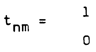
- unm
- x-Koordinate des Anschlusses des Netzes n am Modul m
- vnm
- y-Koordinate des Anschlusses des Netzes n am Modul m
- wn
- Gewichtsfaktor des Netzes n
- Fm
- Flächenbedarf des Moduls m
- r
- Nummer des Plazierungsgebiets PL oder eines Teilgebietes PLT
- Mr C Mb
- Menge der Moduln, auf die die Nebenbedingung r angewandt wird
- Xr, Yr
- Zentrumskoordinaten des r-ten Plazierungsgebiets PL, PLT
- R
- Anzahl der Teilgebiete PLT
- m
- Module number
- n
- Network number
- M = (..., m, ...)
- Quantity of module numbers
- N = (..., n, ...)
- Number of network numbers
- M b CM
- Number of moving modules
- M f CM
- Number of modules fixed
- b
- Number of moving modules
- f
- Number of fixed modules
- x = (... x n ... x m ...)
- Vector of the x coordinates of all networks and modules
- y = (... y n ... y m ...)
- Vector of the y coordinates of all networks and modules
- u nm
- x coordinate of the connection of the network n to the module m
- v nm
- y coordinate of the connection of the network n to the module m
- w n
- Weight factor of the network n
- F m
- Space requirement of the module m
- r
- Number of the PL placement area or a PLT sub-area
- M r C M b
- Set of modules to which the constraint r is applied
- X r , Y r
- Center coordinates of the rth placement area PL, PLT
- R
- Number of sub-areas PLT
Durch den Gewichtsfaktor w kann die Bedeutung eines Netzes festgelegt werden. Mit Hilfe von t wird angegeben, ob ein Netz an einem Modul angeschlossen ist oder nicht.The importance of a network can be determined by the weight factor w. With the help of t it is indicated whether a network is connected to a module or not.
Für den Layout-Entwurf kann es vorteilhaft sein, die Orte der sog. Anschlüsse (Pads) am Rand des Plazierungsgebietes PL nicht fest vorzugeben, sondern sie einem der vier Ränder zuzuordnen und für linke oder rechte Anschlüsse deren y-Koordinate und für obere und für untere Anschlüsse deren x-Koordinate zu berechnen.For the layout design, it can be advantageous not to specify the locations of the so-called connections (pads) on the edge of the placement area PL, but rather one of the four edges assign and calculate their y-coordinate for left or right connections and their x-coordinate for upper and lower connections.
Mit Hilfe des Gleichungssystems 1 werden die Koordinaten der Module berechnet. Anschaulich kann dieses System auch interpretiert werden als ein System von Massenpunkten, die durch elastische Federn mit Federkonstanten verbunden sind. Die Federkonstante entspricht dabei der Wichtigkeit des Netzes, das mit den betrachteten Modul verbunden ist.The coordinates of the modules are calculated using the system of equations 1. Clearly, this system can also be interpreted as a system of mass points that are connected to spring constants by elastic springs. The spring constant corresponds to the importance of the network that is connected to the module under consideration.
Die Lösung des Gleichungssystem 1 führt somit zur Berechnung der Koordinaten aller Module Mb. Ihr Schwerpunkt muß nun einem bestimmten Punkt des Plazierungsgebietes PL zugewiesen werden. Aus diesem Grunde wird eine Nebenbedingung, Formel 2, aufgestellt, die die Zentrumskoordinaten Xr,Yr des Plazierungsgebietes PL angibt. Wenn die Lösung des Gleichungssystems 1 unter Beachtung der Nebenbedingung 2 erfolgt, dann wird der Schwerpunkt der Module auf diese Zentrumskoordinaten gelegt.The solution of the system of equations 1 thus leads to the calculation of the coordinates of all modules M b . Your focus must now be assigned to a specific point in the PL area. For this reason, a secondary condition, Formula 2, is set up, which specifies the center coordinates X r , Y r of the placement area PL. If the solution of the system of equations 1 takes into account the constraint 2, then the focus of the modules is placed on these center coordinates.
Aus Figur 2 ergibt sich die Lage der beweglichen Module Mb innerhalb des Plazierungsgebietes PL. Die Module sind um die Zentrumskoordinaten Xr,Yr angeordnet.The position of the movable modules M b within the placement area PL results from FIG. The modules are arranged around the center coordinates X r , Y r .
Ausführlichere Erläuterungen zur Lösung des Gleichungssystems 1 unter Beachtung der Nebenbedingung 2 für ein Plazierungsgebiet PL kann der eingangs zitierten Literaturstelle Just entnommen werden. Die verwendete Problemformulierung stellt wegen der Konvexität der Zielfunktion auch bei Vorliegen mehrerer linearer Nebenbedingungen 2 sicher, daß ein eindeutiges globales Optimum existiert. Die Lösung kann effizient mit Hilfe bekannter Algorithmen zur Bearbeitung von Problemen der quadratischen Optimierung gewonnen werden, wie sie z.B. in Gill, P.E., Murray, W., Wright, M.H., Practical Optimization, Academic Press, London, 1981 beschrieben sind.More detailed explanations for the solution of the system of equations 1, taking into account the secondary condition 2 for a placement area PL, can be found in the literature reference Just cited at the beginning. Because of the convexity of the objective function, the problem formulation used ensures that there is a clear global optimum even when there are several linear constraints 2. The solution can be obtained efficiently using known algorithms for processing problems of quadratic optimization, such as e.g. in Gill, P.E., Murray, W., Wright, M.H., Practical Optimization, Academic Press, London, 1981.
Nach Figur 7 folgt auf den Schritt S1, bei dem die Module auf dem Plazierungsgebiet PL in Abhängigkeit der Formel 1, 2 plaziert worden sind, der Schritt S2. Nun wird das Plazierungsgebiet PL aufgeteilt (angedeutet durch die Schnittlinie SL in (Fig. 2). Im Partitionierungsschritt wird also das Gebiet, in dem ein Modul angeordnet werden kann, immer weiter eingeschränkt. Die Folge der wiederholten Partitionierungsschritte führt am Verfahrensende zu einer vollständigen Zerlegung der Plazierungsfläche in eben soviele Rechtecke wie Moduln zu plazieren sind und damit zu einer zulässigen Plazierung. Diese unterscheidet sich von den temporären Globalplazierungen dadurch, daß die Moduln überlappungsfrei und gemäß den Regeln des zugehörigen Entwurfsstils angeordnet sind.According to FIG. 7, step S1 follows, in which the modules on the placement area PL depend on the formula 1, 2 have been placed, step S2. Now the placement area PL is divided (indicated by the intersection line SL in (FIG. 2). In the partitioning step, the area in which a module can be arranged is thus restricted further and further. The result of the repeated partitioning steps leads to a complete disassembly at the end of the method The placement area must be placed in as many rectangles as modules and thus in an admissible placement, which differs from the temporary global placements in that the modules are arranged without overlap and in accordance with the rules of the associated design style.
Ein Plazierungsgebiet PL, PLT ist beschrieben durch Breite, Höhe, Fläche, Zentrumskoordinaten und die Menge der Moduln, die in diesem Gebiet plaziert werden sollen.A placement area PL, PLT is described by width, height, area, center coordinates and the number of modules that are to be placed in this area.
Wenn der Schritt S2 zum ersten Mal ausgeführt wird, wird mit dem Plazierungsgebiet PL begonnen, das ist die gesamte Plazierungsfläche, und mit der in diesem Plazierungsgebiet angeordneten Menge aller beweglichen Moduln Mb. Die Partitionierung besteht nun aus zwei Unterschritten:
- 1. Die Modulmenge Mb wird in Untermengen geteilt. Die Teilung erfolgt aufgrund der beim Globalplazierungsschritt berechneten Modulkoordinaten x, y, die ein Minimum bezüglich Netzlängen darstellen. Dies wird bei einer horizontalen bzw. vertikalen Schnittlinie SL durch Sortieren nach y- bzw. x- Koordinaten der Moduln und entsprechender Teilung in zwei oder mehr Teilmengen erreicht. Wenn die Zerlegung bezüglich der Anzahl der von der Schnittlinie SL geschnittenen Netze bestimmt werden soll, ist auch eine zusätzliche Anwendung des Min-Cut-Prinzips auf Moduln in der Nähe der Schnittlinie möglich. Das Min-Cut-Prinzip ist z.B. in Lauther, U., A min-cut placement algorithm for general cell assemblies based on a graph representation, in Design Automation Conference, 1979, S. 1- 10 beschrieben.
Im Ausführungsbeispiel der Figur 2 erfolgt eine Zweiteilung durch eine Schnittlinie SL1 und zwar in vertikaler Richtung.
In diesem Fall ist es zweckmäßig, jedem durch die Zweiteilung erreichten Teilgebiet PLT eine möglichst gleiche Anzahl von Moduln zuzuordnen. Die Zuordnung der Module zu den Teilgebieten PLT kann im Ausführungsbeispiel der Figur 2 nach x-Koordinaten der Module erfolgen, z.B. können die Module mit niedriger x-Koordinate dem linken Teilgebiet und Module mit höherer x-Koordinate dem rechten Teilgebiet zugewiesen werden. - 2. Das Plazierungsgebiet PL wird in nicht überlappende Teilgebiete PLT zerlegt, die das Plazierungsgebiet vollständig und im Verhältnis der Flächen der zugehörigen Moduluntermengen überdecken. Dies führt gewöhnlich dazu, daß die gestrichelte Linie SL in Figur 2 zu verschieben ist. Im Fall eines horizontalen Schnitts werden die Höhen hr' und hr'' der Teilgebiete wie folgt gewählt:

- 1. The module set M b is divided into subsets. The division is based on the module coordinates x, y calculated in the global placement step, which represent a minimum in terms of network lengths. With a horizontal or vertical section line SL, this is achieved by sorting according to the y or x coordinates of the modules and dividing them accordingly into two or more subsets. If the breakdown is to be determined with regard to the number of nets cut by the cutting line SL, an additional application of the min-cut principle to modules near the cutting line is also possible. The min-cut principle is described, for example, in Lauther, U., A min-cut placement algorithm for general cell assemblies based on a graph representation, in Design Automation Conference, 1979, pp. 1-10.
In the exemplary embodiment in FIG. 2, there is a division in two by a cutting line SL1 in the vertical direction.
In this case, it is expedient to assign as equal as possible a number of modules to each sub-area PLT achieved by the division. In the exemplary embodiment in FIG. 2, the modules can be assigned to the sub-areas PLT according to the x-coordinates of the modules, for example the modules with a lower x-coordinate can be assigned to the left sub-area and modules with a higher x-coordinate to the right sub-area. - 2. The placement area PL is broken down into non-overlapping sub-areas PLT, which completely cover the placement area and in the ratio of the areas of the associated module subsets. This usually results in the broken line SL in FIG. 2 having to be shifted. In the case of a horizontal cut, the heights h r ' and h r''of the partial areas are selected as follows:
Nach Durchführung des Schrittes S2 wird wiederum der Globalplazierungsschritt S1 ausgeführt. Das heißt das Gleichungssystem 1 wird neu berechnet, jetzt aber unter Berücksichtigung neuer Nebenbedingungen, und zwar Nebenbedingungen für jedes Teilgebiet PLT. Das heißt die Zentrumskoordinaten Xr und Yr sind nun bezogen auf die durch den Schnitt des Plazierungsgebietes erreichten Teilgebiete PLT. Im Ausführungsbeispiel wären zwei Teilgebiete, so daß nun zwei Nebenbedingungen bei der Berechnung des Gleichungssystems 1 einzuhalten sind. Die Berechnung des Gleichungssystems 1 erfolgt simultan für alle Moduln und wird nicht getrennt für jedes Teilgebiet PLT durchgeführt. Das Ergebnis des Schrittes S1, Globalplazierung, zeigt Figur 3. Es ist zu sehen, daß nunmehr ein Teil der Module dem linken Teilgebiet PLT 1, ein Teil dem rechten Teilgebiet PLT 2 zugeordnet sind. Innerhalb jedes Teilgebietes PLT sind die zugewiesenen Module um deren Zentrumskoordinaten herum gruppiert. Anhand der Buchstaben der Module ist zu erkennen, wie die einzelnen Module sich schwerpunktsmäßig vom Ausgangspunkt der Figur 2 in die Teilgebiete PLT verschoben haben.After step S2, the global placement step S1 is carried out again. This means that the system of equations 1 is recalculated, but now taking new constraints into account, namely constraints for each sub-area PLT. This means that the center coordinates X r and Y r are now related to the sub-areas PLT reached by the intersection of the placement area. In the exemplary embodiment there would be two sub-areas, so that now two constraints for the calculation of the system of equations 1 must be observed. The system of equations 1 is calculated simultaneously for all modules and is not carried out separately for each sub-area PLT. The result of step S1, global placement, is shown in FIG. 3. It can be seen that some of the modules are now assigned to the left sub-area PLT 1 and some to the right sub-area PLT 2. Within each sub-area PLT, the assigned modules are grouped around their center coordinates. The letters of the modules show how the individual modules have shifted from the starting point in FIG. 2 to the sub-areas PLT.
Auf den Globalplazierungsschritt S1 folgt wieder ein Partitionierungsschritt S2 nach den Regeln, die oben beschrieben worden sind. Dazu wird jedes Teilgebiet PLT 1, PLT 2 jeweils durch eine Schnittlinie SL2, SL3 unterteilt und den neu gewonnenen Teilgebieten werden in Abhängigkeit der bei der Globalplazierung gewonnenen Koordinaten die einzelnen Module zugewiesen. Die Größe der Flächen der Teilgebiete wird wiederum im Verhältnis der Flächen der diesen Teilgebieten zugewiesenen Module festgelegt.The global placement step S1 is followed by a partitioning step S2 according to the rules described above. For this purpose, each sub-area PLT 1, PLT 2 is subdivided by an intersection line SL2, SL3 and the individual sub-areas are assigned to the newly acquired sub-areas depending on the coordinates obtained in the global placement. The size of the areas of the sub-areas is in turn determined in the ratio of the areas of the modules assigned to these sub-areas.
Auf den Schritt S2 folgt wiederum der Globalplazierungsschritt S1, d.h. das Gleichungssystem 1 wird nunmehr unter Berücksichtigung der neuen Nebenbedingungen gelöst. Bei einer jeweiligen Zweiteilung der bisherigen Teilgebiete sind nunmehr vier Nebenbedingungen einzuhalten. Das Ergebnis dieser Berechnung zeigt Figur 4. Anschließend an die Globalplazierung erfolgt wiederum eine Partitionierung, Schritt S2.Step S2 is followed by global placement step S1, i.e. System of equations 1 is now solved taking into account the new constraints. With two divisions of the previous sub-areas, four secondary conditions must now be observed. The result of this calculation is shown in FIG. 4. Subsequent to the global placement, there is again a partitioning, step S2.
Die Schritte Globalplazierung S1 und Partitionierung S2 werden solange wiederholt bis entweder für jedes Teilgebiet höchstens noch ein Modul übrig bleibt oder aber pro Teilgebiet höchstens k Module vorgesehen sind. k kann z.B. 8 sein. Beim letzteren Fall ist es erforderlich, die endgültige Anordnung der Module in einem Schritt S3 durchzuführen, bei dem eine optimale Flächenausnutzung angestrebt wird.The steps global placement S1 and partitioning S2 are repeated until either at most one module remains for each sub-area or at most k modules are provided per sub-area. For example, k can be 8. In the latter case, it is necessary to carry out the final arrangement of the modules in a step S3, in which an optimal use of space is sought.
Im Ausführungsbeispiel der Figuren 2 bis 5 kann z.B. mit dem Schritt, der zu Figur 4 geführt hat, die Folge der Globalplazierungen und Partitionierungen abgebrochen werden und die endgültige Lage der Module, die sich aus Figur 5 ergibt, im Schritt S3 ermittelt werden.In the embodiment of Figures 2 to 5, e.g. with the step that led to FIG. 4, the sequence of global placements and partitionings are terminated and the final position of the modules, which results from FIG. 5, is determined in step S3.
Zu Beginn des Optimierungsschrittes S3 liegt eine Zerlegung des gegebenen Plazierungsgebietes derart vor, daß jedem Teilgebiet höchstens die vorgegebene Anzahl k von Moduln zugeordnet ist. Im Optimierungsschritt wird die Flächenausnutzung der erreichten Slicing Struktur sowohl lokal als auch global verbessert.At the beginning of the optimization step S3, the given placement area is broken down in such a way that each sub-area is assigned at most the predetermined number k of modules. In the optimization step, the area utilization of the slicing structure achieved is improved both locally and globally.
Zum lokalen Optimieren jedes Teilgebietes PLT mit höchstens k Modulen werden alle möglichen Zerlegungen dieses Teilgebietes bestimmt und die Moduln den entstandenen Teilflächen zugeordnet. Bei dieser Optimierung werden die Ergebnisse der Globalplazierung berücksichtigt, so daß der Aufwand für die Optimierung reduziert wird. Für jede Zerlegung und Modulzuordnung werden die Abmessungen des kleinsten rechteckigen Gebietes, in dem die Moduln überlappungsfrei plaziert werden können, durch Traversierung der Slicing Struktur berechnet. Die verschiedenen möglichen Abmessungen des gerade behandelten Teilgebietes werden in einer Formfunktion zusammengefaßt. Ein Verfahren, nach dem die Traversierung der Slicing Struktur und die Berechnung der Formfunktionen durchgeführt wird, ist aus La Potin, D.P., Director, S.W.: Mason: A global floorplanning approach for VLSI design, IEEE Transactions on Computer-Aided Design, Band CAD-5, 1986, S. 477-489 bekannt.For local optimization of each sub-area PLT with a maximum of k modules, all possible decompositions of this sub-area are determined and the modules are assigned to the sub-areas created. With this optimization, the results of the global placement are taken into account, so that the effort for the optimization is reduced. For each disassembly and module assignment, the dimensions of the smallest rectangular area in which the modules can be placed without overlap are calculated by traversing the slicing structure. The various possible dimensions of the sub-area just dealt with are summarized in a form function. A method by which the slicing structure is traversed and the shape functions are calculated is from La Potin, DP, Director, SW: Mason: A global floorplanning approach for VLSI design, IEEE Transactions on Computer-Aided Design, Volume CAD 5, 1986, pp. 477-489.
Im Anschluß an die lokale Flächenoptimierung werden durch geeignete Addition der Formfunktionen aller Teilgebiete global die Abmessungen aller erlaubten Modulanordnungen berechnet. Dadurch hat der Anwender die Möglichkeit, die für seine Zwecke optimale Anordnung aus den angebotenen Varianten auszuwählen.Following the local area optimization, the dimensions of all permitted module arrangements are calculated globally by suitable addition of the shape functions of all subregions. This gives the user the opportunity to select the optimal arrangement for his purposes from the variants offered.
Das Prinzip der Partitionierung ist an sich bekannt, es wird jedoch üblicherweise zum Zweck der Verringerung der Problemgröße verwendet. Beim erfindungsgemäßen Verfahren dient es jedoch dem Zweck, die Gebiete, in denen ein Modul angeordnet werden kann, zunehmend einzuschränken. Durch die fortschreitende Verfeinerung der Partitionierung wird am Verfahrensende eine überlappungsfreie Anordnung aller Module erzielt. Das Verfahren ist dabei derart, daß alle Module bis zum Erreichen der überlappungsfreien Anordnung simultan behandelt werden.The principle of partitioning is known per se, but it is usually used for the purpose of reducing the size of the problem. In the method according to the invention, however, it serves the purpose of increasingly restricting the areas in which a module can be arranged. Due to the progressive refinement of the partitioning, an overlap-free arrangement of all modules is achieved at the end of the process. The process is such that all modules are treated simultaneously until the overlap-free arrangement is reached.
Durch mehrmalige Wiederholung der Verfahrensschritte Globalplazierung und Partitionierung und durch die simultane Arbeitsweise werden bessere Ergebnisse erzielt als durch isolierte Anwendung beider Prinzipien.By repeating the global placement and partitioning steps and by working simultaneously, better results are achieved than by using both principles in isolation.
Mit Hilfe des Optimierungsschrittes wird eine optimale Flächenausnutzung erreicht, wobei die Einzelmodule in ihrer Lage auch gedreht werden.With the help of the optimization step, an optimal use of space is achieved, whereby the individual modules are also rotated in their position.
Claims (12)
- Method for placing modules (M) on a carrier (TR) with the aid of a computer and with the use of a module list containing the dimensions and of a network list containing the connections, comprising the following method steps:a) all the movable modules (Mb) are arranged on the placement region (PL) of the carrier (TR) by global placement in such a way that the overall centre of gravity of the modules is situated at the area centre of gravity (Xr, Yr) of the placement region, and all the fixed modules (Mf) are arranged at the edges of the placement region;b) in a partitioning stepb1) the placement region (PL) is subdivided into subregions (PLT),b2) on the basis of the position of the modules fixed in step a), said modules are then split into subsets (Mr) of modules and said subsets are assigned to the subregions (PLT),b3) the size of the subregions is subsequently fixed in the ratio of the subsets (Mr) of modules assigned to the subregions;c) the modules (Mb) are arranged in a global placement simultaneously for all the subregions (PLT) subject to the mutual influence, spread over the subregions, of the connections contained in the network list, in such a way that the overall centres of gravity of the module subsets (Mr) are situated in each case at the area centres of gravity (Xr, Yr) of the assigned subregions (PLT);d) in a further partition stepd1) the subregions are subdivided into further subregions,d2) on the basis of the position of the modules (Mb) fixed in step c), said modules are then assigned to the further subregions (PLT),d3) the size of the further subregions is subsequently ultimately fixed in the ratio of the modules assigned to the further subregions; ande) steps c) and d) are repeated until at most a prescribable number of k modules are assigned to each subregion.
- Method according to Claim 1, characterized in that the prescribed points of the placement region and of the subregions are respectively their centre co-ordinates (Xr, Yr).
- Method according to Claim 2, characterized in that for the purpose of global placement, the x, y co-ordinates of the modules are fixed simultaneously in such a way that


are observed for the placement region (PL) and, respectively, for each subregion (PLT), the symbols having the following significance:m Module numbern Network numberM = (...,m,...) Set of the module numbersN = (...,n,...) Set of the network numbersMb C M Set of the movable modulesMf C M Set of the fixed modulesb Number of the movable modulesf Number of the fixed modulesx = (...xn...xm...) Vector of the x-coordinates of all the networks and modulesy = (...yn...ym...) Vector of the y-coordinates of all the networks and modulesunm x-coordinate of the terminal of the network n at the module mvnm y-coordinate of the terminal of the network n at the module m
If not connectedwn Weighting factor of the network nFm The set surface requirement of the module mr Number of the placement region PL or of the subregion PLTMr C Mb Set of modules to which the secondary condition r is appliedXr, Yr Centre coordinates of the placement region PL, PLTR Number of the subregions PLT - Method according to Claim 3, characterized in that the fixed modules (Mf) can be displaced in the x-direction and y-direction respectively, at the edges of the placement region (PL).
- Method according to Claim 4, characterized in that the assignment of the modules (M) to the subregions (PLT) is performed by sorting the modules according to their x, y coordinates.
- Method according to Claim 5, characterized in that the subdivision of the placement region and of the subregions is performed by horizontal and vertical intersection lines (SL) and module subsets (Mr) are assigned to the subregions (PLT) achieved by the sections.
- Method according to Claim 6, characterized in that in partitioning a bipartitioning of each region is performed in each case.
- Method according to Claim 7, characterized in that modules (M) whose assigned connections transgress the intersection line (SL) are assigned to the subregions (PLT) with the additional application of the min-cut principle.
- Method according to one of Claims 1 to 8, characterized in that the global placement and partitioning are ended when one module (M) (k-1) is arranged in each subregion.
- Method according to one of Claims 1 to 8, characterized in that the optimum area utilization is performed by determining all the possible divisions of the sub-regions (PLT) having up to k modules (M) by utilizing the result of the global placement.
- Method according to Claim 10, characterized in that the arrangement of the modules (M) in the subregions (PLT) is optimized by determining all the possible splits for each subregion and assigning the modules with the sub-areas produced, by calculating for each split and module assignment the dimensions of the smallest rectangular region in which the modules can be placed free from overlap and combining the various possible dimensions of a sub-area in a form function, and by carrying out this for all the subregions (PLT) and calculating the dimensions of all the permissible module arrangements by adding the form functions of all the subregions.
- Method according to Claim 11, characterized in that the rotational positions of the modules are optimized.
Priority Applications (1)
| Application Number | Priority Date | Filing Date | Title |
|---|---|---|---|
| AT89911775T ATE103403T1 (en) | 1988-11-02 | 1989-10-26 | PROCEDURE FOR PLACING MODULES ON A CARRIER. |
Applications Claiming Priority (2)
| Application Number | Priority Date | Filing Date | Title |
|---|---|---|---|
| EP88118251 | 1988-11-02 | ||
| EP88118251 | 1988-11-02 |
Publications (2)
| Publication Number | Publication Date |
|---|---|
| EP0441810A1 EP0441810A1 (en) | 1991-08-21 |
| EP0441810B1 true EP0441810B1 (en) | 1994-03-23 |
Family
ID=8199514
Family Applications (1)
| Application Number | Title | Priority Date | Filing Date |
|---|---|---|---|
| EP89911775A Expired - Lifetime EP0441810B1 (en) | 1988-11-02 | 1989-10-26 | Process for placing modules on a support |
Country Status (5)
| Country | Link |
|---|---|
| US (1) | US5267176A (en) |
| EP (1) | EP0441810B1 (en) |
| JP (1) | JPH04501475A (en) |
| DE (1) | DE58907307D1 (en) |
| WO (1) | WO1990005344A1 (en) |
Families Citing this family (76)
| Publication number | Priority date | Publication date | Assignee | Title |
|---|---|---|---|---|
| US5598344A (en) * | 1990-04-06 | 1997-01-28 | Lsi Logic Corporation | Method and system for creating, validating, and scaling structural description of electronic device |
| JP3220250B2 (en) * | 1992-01-09 | 2001-10-22 | 株式会社東芝 | Cell automatic placement method |
| US5566078A (en) * | 1993-05-26 | 1996-10-15 | Lsi Logic Corporation | Integrated circuit cell placement using optimization-driven clustering |
| US5598343A (en) * | 1993-10-01 | 1997-01-28 | Texas Instruments Incorporated | Method of segmenting an FPGA channel architecture for maximum routability and performance |
| JP2922404B2 (en) * | 1993-11-15 | 1999-07-26 | 富士通株式会社 | Method for determining layout of integrated circuit |
| US5818726A (en) * | 1994-04-18 | 1998-10-06 | Cadence Design Systems, Inc. | System and method for determining acceptable logic cell locations and generating a legal location structure |
| US5557533A (en) * | 1994-04-19 | 1996-09-17 | Lsi Logic Corporation | Cell placement alteration apparatus for integrated circuit chip physical design automation system |
| US6155725A (en) * | 1994-04-19 | 2000-12-05 | Lsi Logic Corporation | Cell placement representation and transposition for integrated circuit physical design automation system |
| US5963975A (en) * | 1994-04-19 | 1999-10-05 | Lsi Logic Corporation | Single chip integrated circuit distributed shared memory (DSM) and communications nodes |
| US5875117A (en) * | 1994-04-19 | 1999-02-23 | Lsi Logic Corporation | Simultaneous placement and routing (SPAR) method for integrated circuit physical design automation system |
| US5914887A (en) * | 1994-04-19 | 1999-06-22 | Lsi Logic Corporation | Congestion based cost factor computing apparatus for integrated circuit physical design automation system |
| US5495419A (en) * | 1994-04-19 | 1996-02-27 | Lsi Logic Corporation | Integrated circuit physical design automation system utilizing optimization process decomposition and parallel processing |
| US6493658B1 (en) | 1994-04-19 | 2002-12-10 | Lsi Logic Corporation | Optimization processing for integrated circuit physical design automation system using optimally switched fitness improvement algorithms |
| US5815403A (en) * | 1994-04-19 | 1998-09-29 | Lsi Logic Corporation | Fail-safe distributive processing method for producing a highest fitness cell placement for an integrated circuit chip |
| US5535134A (en) * | 1994-06-03 | 1996-07-09 | International Business Machines Corporation | Object placement aid |
| US5638293A (en) * | 1994-09-13 | 1997-06-10 | Lsi Logic Corporation | Optimal pad location method for microelectronic circuit cell placement |
| US5696693A (en) * | 1995-03-31 | 1997-12-09 | Unisys Corporation | Method for placing logic functions and cells in a logic design using floor planning by analogy |
| JP3504394B2 (en) * | 1995-09-08 | 2004-03-08 | 松下電器産業株式会社 | How to create component array data |
| US5818722A (en) * | 1995-11-03 | 1998-10-06 | Yoji Kajitani | Method of placing and extracting modules |
| US6308143B1 (en) * | 1996-02-21 | 2001-10-23 | Matsushita Electric Industrial Co., Ltd. | Layout input apparatus, layout input method, layout verification apparatus, and layout verification method |
| US5818729A (en) * | 1996-05-23 | 1998-10-06 | Synopsys, Inc. | Method and system for placing cells using quadratic placement and a spanning tree model |
| US5798936A (en) * | 1996-06-21 | 1998-08-25 | Avant| Corporation | Congestion-driven placement method and computer-implemented integrated-circuit design tool |
| US5870311A (en) * | 1996-06-28 | 1999-02-09 | Lsi Logic Corporation | Advanced modular cell placement system with fast procedure for finding a levelizing cut point |
| US5892688A (en) * | 1996-06-28 | 1999-04-06 | Lsi Logic Corporation | Advanced modular cell placement system with iterative one dimensional preplacement optimization |
| US5867398A (en) * | 1996-06-28 | 1999-02-02 | Lsi Logic Corporation | Advanced modular cell placement system with density driven capacity penalty system |
| US5808899A (en) * | 1996-06-28 | 1998-09-15 | Lsi Logic Corporation | Advanced modular cell placement system with cell placement crystallization |
| US5831863A (en) * | 1996-06-28 | 1998-11-03 | Lsi Logic Corporation | Advanced modular cell placement system with wire length driven affinity system |
| US5870312A (en) * | 1996-06-28 | 1999-02-09 | Lsi Logic Corporation | Advanced modular cell placement system with dispersion-driven levelizing system |
| US5835381A (en) * | 1996-06-28 | 1998-11-10 | Lsi Logic Corporation | Advanced modular cell placement system with minimizing maximal cut driven affinity system |
| US5872718A (en) * | 1996-06-28 | 1999-02-16 | Lsi Logic Corporation | Advanced modular cell placement system |
| US5844811A (en) * | 1996-06-28 | 1998-12-01 | Lsi Logic Corporation | Advanced modular cell placement system with universal affinity driven discrete placement optimization |
| US6067409A (en) * | 1996-06-28 | 2000-05-23 | Lsi Logic Corporation | Advanced modular cell placement system |
| US5812740A (en) * | 1996-06-28 | 1998-09-22 | Lsi Logic Corporation | Advanced modular cell placement system with neighborhood system driven optimization |
| US6085032A (en) * | 1996-06-28 | 2000-07-04 | Lsi Logic Corporation | Advanced modular cell placement system with sinusoidal optimization |
| US5914888A (en) * | 1996-06-28 | 1999-06-22 | Lsi Logic Corporation | Advanced modular cell placement system with coarse overflow remover |
| US5963455A (en) * | 1996-06-28 | 1999-10-05 | Lsi Logic Corporation | Advanced modular cell placement system with functional sieve optimization technique |
| US6030110A (en) * | 1996-06-28 | 2000-02-29 | Lsi Logic Corporation | Advanced modular cell placement system with median control and increase in resolution |
| US6026223A (en) * | 1996-06-28 | 2000-02-15 | Scepanovic; Ranko | Advanced modular cell placement system with overlap remover with minimal noise |
| US5980093A (en) * | 1996-12-04 | 1999-11-09 | Lsi Logic Corporation | Integrated circuit layout routing using multiprocessing |
| US6718520B1 (en) | 1997-01-27 | 2004-04-06 | Unisys Corporation | Method and apparatus for selectively providing hierarchy to a circuit design |
| US6754879B1 (en) | 1997-01-27 | 2004-06-22 | Unisys Corporation | Method and apparatus for providing modularity to a behavioral description of a circuit design |
| US6378114B1 (en) * | 1997-07-01 | 2002-04-23 | Synopsys, Inc. | Method for the physical placement of an integrated circuit adaptive to netlist changes |
| US6385760B2 (en) * | 1998-06-12 | 2002-05-07 | Monterey Design Systems, Inc. | System and method for concurrent placement of gates and associated wiring |
| US6378119B1 (en) * | 1999-05-24 | 2002-04-23 | Dell Usa, L.P. | Method and system for adaptive component placement |
| US6415426B1 (en) | 2000-06-02 | 2002-07-02 | Incentia Design Systems, Inc. | Dynamic weighting and/or target zone analysis in timing driven placement of cells of an integrated circuit design |
| US6516455B1 (en) * | 2000-12-06 | 2003-02-04 | Cadence Design Systems, Inc. | Partitioning placement method using diagonal cutlines |
| US6826737B2 (en) * | 2000-12-06 | 2004-11-30 | Cadence Design Systems, Inc. | Recursive partitioning placement method and apparatus |
| CN1529864B (en) * | 2000-12-06 | 2010-05-05 | 凯登斯设计系统有限公司 | Method and apparatus for considering diagonal wiring in placement |
| US7003754B2 (en) * | 2000-12-07 | 2006-02-21 | Cadence Design Systems, Inc. | Routing method and apparatus that use of diagonal routes |
| US6957410B2 (en) | 2000-12-07 | 2005-10-18 | Cadence Design Systems, Inc. | Method and apparatus for adaptively selecting the wiring model for a design region |
| US7024650B2 (en) * | 2000-12-06 | 2006-04-04 | Cadence Design Systems, Inc. | Method and apparatus for considering diagonal wiring in placement |
| US7080336B2 (en) | 2000-12-06 | 2006-07-18 | Cadence Design Systems, Inc. | Method and apparatus for computing placement costs |
| US7055120B2 (en) | 2000-12-06 | 2006-05-30 | Cadence Design Systems, Inc. | Method and apparatus for placing circuit modules |
| US7073150B2 (en) | 2000-12-07 | 2006-07-04 | Cadence Design Systems, Inc. | Hierarchical routing method and apparatus that use diagonal routes |
| US6915501B2 (en) | 2001-01-19 | 2005-07-05 | Cadence Design Systems, Inc. | LP method and apparatus for identifying routes |
| US6738960B2 (en) * | 2001-01-19 | 2004-05-18 | Cadence Design Systems, Inc. | Method and apparatus for producing sub-optimal routes for a net by generating fake configurations |
| US6507937B1 (en) * | 2001-06-19 | 2003-01-14 | Lsi Logic Corporation | Method of global placement of control cells and hardmac pins in a datapath macro for an integrated circuit design |
| US6877149B2 (en) | 2001-08-23 | 2005-04-05 | Cadence Design Systems, Inc. | Method and apparatus for pre-computing routes |
| US6795958B2 (en) | 2001-08-23 | 2004-09-21 | Cadence Design Systems, Inc. | Method and apparatus for generating routes for groups of related node configurations |
| US7143382B2 (en) | 2001-08-23 | 2006-11-28 | Cadence Design Systems, Inc. | Method and apparatus for storing routes |
| US6931616B2 (en) * | 2001-08-23 | 2005-08-16 | Cadence Design Systems, Inc. | Routing method and apparatus |
| US7058913B1 (en) | 2001-09-06 | 2006-06-06 | Cadence Design Systems, Inc. | Analytical placement method and apparatus |
| US7225116B2 (en) * | 2002-08-20 | 2007-05-29 | Cadence Design Systems, Inc. | Method for eliminating routing congestion in an IC layout |
| US7624367B2 (en) | 2002-11-18 | 2009-11-24 | Cadence Design Systems, Inc. | Method and system for routing |
| US7010771B2 (en) * | 2002-11-18 | 2006-03-07 | Cadence Design Systems, Inc. | Method and apparatus for searching for a global path |
| US6988257B2 (en) * | 2002-11-18 | 2006-01-17 | Cadence Design Systems, Inc. | Method and apparatus for routing |
| US7171635B2 (en) * | 2002-11-18 | 2007-01-30 | Cadence Design Systems, Inc. | Method and apparatus for routing |
| US7480885B2 (en) * | 2002-11-18 | 2009-01-20 | Cadence Design Systems, Inc. | Method and apparatus for routing with independent goals on different layers |
| US7080342B2 (en) * | 2002-11-18 | 2006-07-18 | Cadence Design Systems, Inc | Method and apparatus for computing capacity of a region for non-Manhattan routing |
| US7003752B2 (en) * | 2002-11-18 | 2006-02-21 | Cadence Design Systems, Inc. | Method and apparatus for routing |
| US6996789B2 (en) * | 2002-11-18 | 2006-02-07 | Cadence Design Systems, Inc. | Method and apparatus for performing an exponential path search |
| US7047513B2 (en) * | 2002-11-18 | 2006-05-16 | Cadence Design Systems, Inc. | Method and apparatus for searching for a three-dimensional global path |
| US7506295B1 (en) | 2002-12-31 | 2009-03-17 | Cadence Design Systems, Inc. | Non manhattan floor plan architecture for integrated circuits |
| US7089519B1 (en) | 2002-12-31 | 2006-08-08 | Cadence Design System, Inc. | Method and system for performing placement on non Manhattan semiconductor integrated circuits |
| US7013445B1 (en) | 2002-12-31 | 2006-03-14 | Cadence Design Systems, Inc. | Post processor for optimizing manhattan integrated circuits placements into non manhattan placements |
| US8032855B1 (en) * | 2005-12-06 | 2011-10-04 | Altera Corporation | Method and apparatus for performing incremental placement on a structured application specific integrated circuit |
Family Cites Families (7)
| Publication number | Priority date | Publication date | Assignee | Title |
|---|---|---|---|---|
| US3629843A (en) * | 1970-05-11 | 1971-12-21 | Bell Telephone Labor Inc | Machine process for assigning interconnected components to locations in a planar matrix |
| US4342090A (en) * | 1980-06-27 | 1982-07-27 | International Business Machines Corp. | Batch chip placement system |
| US4593363A (en) * | 1983-08-12 | 1986-06-03 | International Business Machines Corporation | Simultaneous placement and wiring for VLSI chips |
| US4577276A (en) * | 1983-09-12 | 1986-03-18 | At&T Bell Laboratories | Placement of components on circuit substrates |
| US4630219A (en) * | 1983-11-23 | 1986-12-16 | International Business Machines Corporation | Element placement method |
| US4908772A (en) * | 1987-03-30 | 1990-03-13 | Bell Telephone Laboratories | Integrated circuits with component placement by rectilinear partitioning |
| US4852015A (en) * | 1987-06-24 | 1989-07-25 | Eta Systems, Inc. | Automatic circuit layout router |
-
1989
- 1989-10-26 EP EP89911775A patent/EP0441810B1/en not_active Expired - Lifetime
- 1989-10-26 JP JP1511083A patent/JPH04501475A/en active Pending
- 1989-10-26 WO PCT/DE1989/000688 patent/WO1990005344A1/en active IP Right Grant
- 1989-10-26 DE DE89911775T patent/DE58907307D1/en not_active Expired - Fee Related
- 1989-10-26 US US07/684,902 patent/US5267176A/en not_active Expired - Fee Related
Also Published As
| Publication number | Publication date |
|---|---|
| DE58907307D1 (en) | 1994-04-28 |
| EP0441810A1 (en) | 1991-08-21 |
| JPH04501475A (en) | 1992-03-12 |
| US5267176A (en) | 1993-11-30 |
| WO1990005344A1 (en) | 1990-05-17 |
Similar Documents
| Publication | Publication Date | Title |
|---|---|---|
| EP0441810B1 (en) | Process for placing modules on a support | |
| DE112007002221B4 (en) | Graphical layout with maximum page coverage and minimal content removal | |
| DE69813892T2 (en) | POLYGON DISPLAY IN THE LAYOUT OF AN INTEGRATED CIRCUIT | |
| DE102019116997B4 (en) | TAP CELLS, METHOD OF DESIGN THEREOF AND CIRCUIT DESIGN SYSTEM | |
| DE102017124097A1 (en) | POWER NETWORK STRUCTURES AND METHOD FOR THE PRODUCTION THEREOF | |
| DE10025583A1 (en) | Integrated circuit cell layout optimisation method has initial cell layout automatically modified after optimisation of component dimensions | |
| DE69532307T2 (en) | Expression propagation for hierarchical net lists | |
| DE102016118811B4 (en) | Integrated circuits with staggered conductive features and methods of configuring an integrated circuit layout | |
| DE102014112789A1 (en) | Cell layout and structure | |
| DE102020127462B4 (en) | SEMICONDUCTOR DEVICE AND METHOD FOR PRODUCING SAME | |
| DE102019124928A1 (en) | INTEGRATED CIRCUIT DESIGN USING FUZZY MACHINE LEARNERS | |
| EP1141867B1 (en) | Method and arrangement for verifying the layout of an integrated circuit with the aid of a computer and use thereof in the production of an integrated circuit | |
| DE10205330A1 (en) | Method for correcting optical neighborhood effects | |
| DE112004001651B4 (en) | Automatic layout conversion system and method | |
| DE102016111337A1 (en) | Method for increasing the decoupling capacity in a microelectronic circuit | |
| DE10317924A1 (en) | Layout design method and system for providing bypass capacity and compliant density in an integrated circuit | |
| DE602004012696T2 (en) | Method for analyzing electrical components, device for analyzing electronic components and electrical components using same | |
| DE10206658B4 (en) | Method for checking an integrated electrical circuit | |
| DE2837574A1 (en) | DRIVERS FOR INTEGRATED CIRCUITS | |
| DE10317376A1 (en) | Layout data backup method, layout data conversion device and graphics verification device | |
| DE102020130215A1 (en) | Techniques for transposing a matrix by using a block of memory | |
| CH676304A5 (en) | ||
| DE69737771T2 (en) | MODULAR CELL PLACEMENT SYSTEM WITH FAST METHOD FOR FINDING A LEVELING INTERFACE | |
| DE102012106130A1 (en) | Simplified PV system creation with a consecutively placed system block | |
| EP4026036B1 (en) | Method for establishing a structure of a topology of a defined limited area for drainage of same |
Legal Events
| Date | Code | Title | Description |
|---|---|---|---|
| PUAI | Public reference made under article 153(3) epc to a published international application that has entered the european phase |
Free format text: ORIGINAL CODE: 0009012 |
|
| 17P | Request for examination filed |
Effective date: 19910424 |
|
| AK | Designated contracting states |
Kind code of ref document: A1 Designated state(s): AT BE DE FR GB IT NL |
|
| 17Q | First examination report despatched |
Effective date: 19920731 |
|
| GRAA | (expected) grant |
Free format text: ORIGINAL CODE: 0009210 |
|
| AK | Designated contracting states |
Kind code of ref document: B1 Designated state(s): AT BE DE FR GB IT NL |
|
| REF | Corresponds to: |
Ref document number: 103403 Country of ref document: AT Date of ref document: 19940415 Kind code of ref document: T |
|
| RIN1 | Information on inventor provided before grant (corrected) |
Inventor name: SIGL, GEORG Inventor name: KLEINHANS, JUERGEN Inventor name: JOHANNES, FRANK Inventor name: ANTREICH, KURT |
|
| REF | Corresponds to: |
Ref document number: 58907307 Country of ref document: DE Date of ref document: 19940428 |
|
| ITF | It: translation for a ep patent filed |
Owner name: STUDIO JAUMANN |
|
| GBT | Gb: translation of ep patent filed (gb section 77(6)(a)/1977) |
Effective date: 19940607 |
|
| ET | Fr: translation filed | ||
| PLBE | No opposition filed within time limit |
Free format text: ORIGINAL CODE: 0009261 |
|
| STAA | Information on the status of an ep patent application or granted ep patent |
Free format text: STATUS: NO OPPOSITION FILED WITHIN TIME LIMIT |
|
| 26N | No opposition filed | ||
| PGFP | Annual fee paid to national office [announced via postgrant information from national office to epo] |
Ref country code: GB Payment date: 19970909 Year of fee payment: 9 |
|
| PGFP | Annual fee paid to national office [announced via postgrant information from national office to epo] |
Ref country code: AT Payment date: 19970926 Year of fee payment: 9 |
|
| PGFP | Annual fee paid to national office [announced via postgrant information from national office to epo] |
Ref country code: BE Payment date: 19971013 Year of fee payment: 9 |
|
| PGFP | Annual fee paid to national office [announced via postgrant information from national office to epo] |
Ref country code: NL Payment date: 19971029 Year of fee payment: 9 Ref country code: FR Payment date: 19971029 Year of fee payment: 9 |
|
| PGFP | Annual fee paid to national office [announced via postgrant information from national office to epo] |
Ref country code: DE Payment date: 19971218 Year of fee payment: 9 |
|
| PG25 | Lapsed in a contracting state [announced via postgrant information from national office to epo] |
Ref country code: GB Free format text: LAPSE BECAUSE OF NON-PAYMENT OF DUE FEES Effective date: 19981026 Ref country code: AT Free format text: LAPSE BECAUSE OF NON-PAYMENT OF DUE FEES Effective date: 19981026 |
|
| PG25 | Lapsed in a contracting state [announced via postgrant information from national office to epo] |
Ref country code: BE Free format text: LAPSE BECAUSE OF NON-PAYMENT OF DUE FEES Effective date: 19981031 |
|
| BERE | Be: lapsed |
Owner name: SIEMENS A.G. Effective date: 19981031 |
|
| PG25 | Lapsed in a contracting state [announced via postgrant information from national office to epo] |
Ref country code: NL Free format text: LAPSE BECAUSE OF NON-PAYMENT OF DUE FEES Effective date: 19990501 |
|
| GBPC | Gb: european patent ceased through non-payment of renewal fee |
Effective date: 19981026 |
|
| PG25 | Lapsed in a contracting state [announced via postgrant information from national office to epo] |
Ref country code: FR Free format text: LAPSE BECAUSE OF NON-PAYMENT OF DUE FEES Effective date: 19990630 |
|
| NLV4 | Nl: lapsed or anulled due to non-payment of the annual fee |
Effective date: 19990501 |
|
| REG | Reference to a national code |
Ref country code: FR Ref legal event code: ST |
|
| PG25 | Lapsed in a contracting state [announced via postgrant information from national office to epo] |
Ref country code: DE Free format text: LAPSE BECAUSE OF NON-PAYMENT OF DUE FEES Effective date: 19990803 |
|
| PG25 | Lapsed in a contracting state [announced via postgrant information from national office to epo] |
Ref country code: IT Free format text: LAPSE BECAUSE OF NON-PAYMENT OF DUE FEES;WARNING: LAPSES OF ITALIAN PATENTS WITH EFFECTIVE DATE BEFORE 2007 MAY HAVE OCCURRED AT ANY TIME BEFORE 2007. THE CORRECT EFFECTIVE DATE MAY BE DIFFERENT FROM THE ONE RECORDED. Effective date: 20051026 |