EP0441650B1 - Schmelz-Kontrolleinheit - Google Patents
Schmelz-Kontrolleinheit Download PDFInfo
- Publication number
- EP0441650B1 EP0441650B1 EP91301044A EP91301044A EP0441650B1 EP 0441650 B1 EP0441650 B1 EP 0441650B1 EP 91301044 A EP91301044 A EP 91301044A EP 91301044 A EP91301044 A EP 91301044A EP 0441650 B1 EP0441650 B1 EP 0441650B1
- Authority
- EP
- European Patent Office
- Prior art keywords
- control unit
- receiver
- transmitter
- casing
- fusion control
- Prior art date
- Legal status (The legal status is an assumption and is not a legal conclusion. Google has not performed a legal analysis and makes no representation as to the accuracy of the status listed.)
- Expired - Lifetime
Links
Images


Classifications
-
- G—PHYSICS
- G05—CONTROLLING; REGULATING
- G05B—CONTROL OR REGULATING SYSTEMS IN GENERAL; FUNCTIONAL ELEMENTS OF SUCH SYSTEMS; MONITORING OR TESTING ARRANGEMENTS FOR SUCH SYSTEMS OR ELEMENTS
- G05B19/00—Program-control systems
- G05B19/02—Program-control systems electric
- G05B19/04—Program control other than numerical control, i.e. in sequence controllers or logic controllers
- G05B19/042—Program control other than numerical control, i.e. in sequence controllers or logic controllers using digital processors
- G05B19/0423—Input/output
-
- B—PERFORMING OPERATIONS; TRANSPORTING
- B29—WORKING OF PLASTICS; WORKING OF SUBSTANCES IN A PLASTIC STATE IN GENERAL
- B29C—SHAPING OR JOINING OF PLASTICS; SHAPING OF MATERIAL IN A PLASTIC STATE, NOT OTHERWISE PROVIDED FOR; AFTER-TREATMENT OF THE SHAPED PRODUCTS, e.g. REPAIRING
- B29C65/00—Joining or sealing of preformed parts, e.g. welding of plastics materials; Apparatus therefor
- B29C65/02—Joining or sealing of preformed parts, e.g. welding of plastics materials; Apparatus therefor by heating, with or without pressure
- B29C65/34—Joining or sealing of preformed parts, e.g. welding of plastics materials; Apparatus therefor by heating, with or without pressure using heated elements which remain in the joint, e.g. "verlorenes Schweisselement"
- B29C65/3472—Joining or sealing of preformed parts, e.g. welding of plastics materials; Apparatus therefor by heating, with or without pressure using heated elements which remain in the joint, e.g. "verlorenes Schweisselement" characterised by the composition of the heated elements which remain in the joint
- B29C65/3476—Joining or sealing of preformed parts, e.g. welding of plastics materials; Apparatus therefor by heating, with or without pressure using heated elements which remain in the joint, e.g. "verlorenes Schweisselement" characterised by the composition of the heated elements which remain in the joint being metallic
-
- B—PERFORMING OPERATIONS; TRANSPORTING
- B29—WORKING OF PLASTICS; WORKING OF SUBSTANCES IN A PLASTIC STATE IN GENERAL
- B29C—SHAPING OR JOINING OF PLASTICS; SHAPING OF MATERIAL IN A PLASTIC STATE, NOT OTHERWISE PROVIDED FOR; AFTER-TREATMENT OF THE SHAPED PRODUCTS, e.g. REPAIRING
- B29C66/00—General aspects of processes or apparatus for joining preformed parts
- B29C66/50—General aspects of joining tubular articles; General aspects of joining long products, i.e. bars or profiled elements; General aspects of joining single elements to tubular articles, hollow articles or bars; General aspects of joining several hollow-preforms to form hollow or tubular articles
- B29C66/51—Joining tubular articles, profiled elements or bars; Joining single elements to tubular articles, hollow articles or bars; Joining several hollow-preforms to form hollow or tubular articles
- B29C66/52—Joining tubular articles, bars or profiled elements
- B29C66/522—Joining tubular articles
- B29C66/5229—Joining tubular articles involving the use of a socket
-
- B—PERFORMING OPERATIONS; TRANSPORTING
- B29—WORKING OF PLASTICS; WORKING OF SUBSTANCES IN A PLASTIC STATE IN GENERAL
- B29C—SHAPING OR JOINING OF PLASTICS; SHAPING OF MATERIAL IN A PLASTIC STATE, NOT OTHERWISE PROVIDED FOR; AFTER-TREATMENT OF THE SHAPED PRODUCTS, e.g. REPAIRING
- B29C66/00—General aspects of processes or apparatus for joining preformed parts
- B29C66/90—Measuring or controlling the joining process
- B29C66/91—Measuring or controlling the joining process by measuring or controlling the temperature, the heat or the thermal flux
- B29C66/914—Measuring or controlling the joining process by measuring or controlling the temperature, the heat or the thermal flux by controlling or regulating the temperature, the heat or the thermal flux
- B29C66/9161—Measuring or controlling the joining process by measuring or controlling the temperature, the heat or the thermal flux by controlling or regulating the temperature, the heat or the thermal flux by controlling or regulating the heat or the thermal flux, i.e. the heat flux
- B29C66/91651—Measuring or controlling the joining process by measuring or controlling the temperature, the heat or the thermal flux by controlling or regulating the temperature, the heat or the thermal flux by controlling or regulating the heat or the thermal flux, i.e. the heat flux by controlling or regulating the heat generated by Joule heating or induction heating
- B29C66/91655—Measuring or controlling the joining process by measuring or controlling the temperature, the heat or the thermal flux by controlling or regulating the temperature, the heat or the thermal flux by controlling or regulating the heat or the thermal flux, i.e. the heat flux by controlling or regulating the heat generated by Joule heating or induction heating by controlling or regulating the current intensity
-
- B—PERFORMING OPERATIONS; TRANSPORTING
- B29—WORKING OF PLASTICS; WORKING OF SUBSTANCES IN A PLASTIC STATE IN GENERAL
- B29C—SHAPING OR JOINING OF PLASTICS; SHAPING OF MATERIAL IN A PLASTIC STATE, NOT OTHERWISE PROVIDED FOR; AFTER-TREATMENT OF THE SHAPED PRODUCTS, e.g. REPAIRING
- B29C66/00—General aspects of processes or apparatus for joining preformed parts
- B29C66/90—Measuring or controlling the joining process
- B29C66/96—Measuring or controlling the joining process characterised by the method for implementing the controlling of the joining process
- B29C66/967—Measuring or controlling the joining process characterised by the method for implementing the controlling of the joining process involving special data inputs or special data outputs, e.g. for monitoring purposes
- B29C66/9672—Measuring or controlling the joining process characterised by the method for implementing the controlling of the joining process involving special data inputs or special data outputs, e.g. for monitoring purposes involving special data inputs, e.g. involving barcodes, RFID tags
-
- G—PHYSICS
- G05—CONTROLLING; REGULATING
- G05B—CONTROL OR REGULATING SYSTEMS IN GENERAL; FUNCTIONAL ELEMENTS OF SUCH SYSTEMS; MONITORING OR TESTING ARRANGEMENTS FOR SUCH SYSTEMS OR ELEMENTS
- G05B2219/00—Program-control systems
- G05B2219/20—Pc systems
- G05B2219/23—Pc programming
- G05B2219/23051—Remote control, enter program remote, detachable programmer
-
- G—PHYSICS
- G05—CONTROLLING; REGULATING
- G05B—CONTROL OR REGULATING SYSTEMS IN GENERAL; FUNCTIONAL ELEMENTS OF SUCH SYSTEMS; MONITORING OR TESTING ARRANGEMENTS FOR SUCH SYSTEMS OR ELEMENTS
- G05B2219/00—Program-control systems
- G05B2219/20—Pc systems
- G05B2219/25—Pc structure of the system
- G05B2219/25192—Infrared
-
- G—PHYSICS
- G05—CONTROLLING; REGULATING
- G05B—CONTROL OR REGULATING SYSTEMS IN GENERAL; FUNCTIONAL ELEMENTS OF SUCH SYSTEMS; MONITORING OR TESTING ARRANGEMENTS FOR SUCH SYSTEMS OR ELEMENTS
- G05B2219/00—Program-control systems
- G05B2219/20—Pc systems
- G05B2219/25—Pc structure of the system
- G05B2219/25462—Galvanic separation, galvanic isolation
-
- G—PHYSICS
- G05—CONTROLLING; REGULATING
- G05B—CONTROL OR REGULATING SYSTEMS IN GENERAL; FUNCTIONAL ELEMENTS OF SUCH SYSTEMS; MONITORING OR TESTING ARRANGEMENTS FOR SUCH SYSTEMS OR ELEMENTS
- G05B2219/00—Program-control systems
- G05B2219/30—Nc systems
- G05B2219/33—Director till display
- G05B2219/33229—Differential amplifier, xor to cancel noise, balanced rs422
-
- G—PHYSICS
- G05—CONTROLLING; REGULATING
- G05B—CONTROL OR REGULATING SYSTEMS IN GENERAL; FUNCTIONAL ELEMENTS OF SUCH SYSTEMS; MONITORING OR TESTING ARRANGEMENTS FOR SUCH SYSTEMS OR ELEMENTS
- G05B2219/00—Program-control systems
- G05B2219/30—Nc systems
- G05B2219/36—Nc in input of data, input key till input tape
- G05B2219/36114—Eprom, prom
-
- G—PHYSICS
- G05—CONTROLLING; REGULATING
- G05B—CONTROL OR REGULATING SYSTEMS IN GENERAL; FUNCTIONAL ELEMENTS OF SUCH SYSTEMS; MONITORING OR TESTING ARRANGEMENTS FOR SUCH SYSTEMS OR ELEMENTS
- G05B2219/00—Program-control systems
- G05B2219/30—Nc systems
- G05B2219/36—Nc in input of data, input key till input tape
- G05B2219/36159—Detachable or portable programming unit, display, pc, pda
-
- G—PHYSICS
- G05—CONTROLLING; REGULATING
- G05B—CONTROL OR REGULATING SYSTEMS IN GENERAL; FUNCTIONAL ELEMENTS OF SUCH SYSTEMS; MONITORING OR TESTING ARRANGEMENTS FOR SUCH SYSTEMS OR ELEMENTS
- G05B2219/00—Program-control systems
- G05B2219/30—Nc systems
- G05B2219/37—Measurements
- G05B2219/37266—Infrared
Definitions
- This invention relates to Fusion Control Units particularly for use in the control of the fusion or welding current applied to heater wires contained in plastic fittings such as pipe fittings.
- fittings containing an electrical heater wire wound internally in the tubular fitting and adapted, when heated, to cause the adjacent plastic material to melt and to fuse with the material of the pipes to be joined.
- heater wire Different kinds are used in different fittings. In general low resistance wires made of copper and copper alloys are used and high resistance wires made of aluminium and aluminium alloys are used in other applications. It is important to be able to distinguish between these different types of windings and in order to do so not only the ohmic resistance but also the inductance has to be measured.
- This regime may be controlled, as in the present invention, by use of a computer or microprocessor which may also carry out other functions.
- the computer or microprocessor may record the type of fitting which is being used, the period for which current was applied, the strength of the current and so on.
- EP-A-0353912 discloses a fusion control unit equipped with a transmitter receiver for interrogating an information containing element provided in the body of a pipe fitting.
- the fusion control unit contains the transmitter receiver and supplies an interrogating signal in the form of an RF signal via a lead to antennae.
- the main object of the present invention is to provide a fusion control unit in which the programme set up in the computer or microprocessor may be varied and/or information contained in the computer or microprocessor may be extracted, without the need to get inside the casing of the fusion control unit and without the need for any electrical or mechanical connections passing through the wall of the control unit.
- the unit may be totally sealed and made water and pressure proof and does not have to be disturbed in order to be reprogrammed or in order to extract information from the computer or microprocessor.
- Fusion control units are generally used in the field to join either new or replacement lengths of pipe, for example water or gas pipes. It is important to provide a watertight unit for use in the field. In addition, when replacing gas pipes, it is important to prevent ingress of gas.
- a fusion control unit comprised within a casing containing means to apply fusion welding current to an electric heater wire in a plastic fitting, under the control of a computer or microprocessor contained in the unit, characterised by means, within the casing, to enable information to be extracted from the computer or microprocessor, or to enable the reprogramming of the computer or microprocessor, without the need to gain access to the inside of the unit and without the use of electrical or other connectors passing through the casing of the unit.
- the means within the casing comprises infra-red transmitter and receiver devices coupled through amplifiers and through a serial or parallel communication interface to the computer or microprocessor and adapted to cooperate with an external optical communication box.
- the optical communication box may comprise infra-red transmitter and receiver devices connected through amplifiers to a serial or parallel communication interface connector.
- the casing of the control unit has a wall made of the material which offers low impedance to transmission of infra-red radiation and said means within the casing is preferably located adjacent to said wall.
- Any wall of the casing may be used, provided it is of low impedance.
- the optical communications box may be brought up to the low impedance wall of the casing and held or clamped opposite to the internal means adapted to receive the infra-red radiation which may contain digitally encoded information which may be a new programme code or may set up new parameters or may contain information to be stored and transmitted into the unit.
- the unit may be arranged to transmit from the microprocessor or computer through the infra-red arrangements to the external optical communication box or interface.
- the additional devices may be in parallel with the transmitter and receiver devices in both the control unit and the optical communications box.
- the additional devices may comprise, in parallel with each original amplifier and transmitter, an inverting transmitter and an additional transmitter; and in parallel with each original receiver and additional receiver feeding into a differential amplifier which also receives the output of the original receiver.
- the means within the casing may comprise a Hall effect transducer and an electromagnetic transducer adapted to cooperate with a corresponding transducer and receiver in an external communications box.
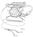
- the fusion control unit which comprises a casing 10 which has a front panel 11 made of a plastic material which offers low impedance to transmission of infra-red signals.
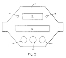
- a microprocessor Within the casing is a microprocessor and the microprocessor is arranged to display fusion information in its display panel 12 and operator instructions in a display panel 13. These display panels are shown more clearly in Figure 2.
- the casing of the unit is completely sealed against water and can stand high pressures and is made of a material highly resistance to corrosion.
- the casing rests on legs 19 and 20 and also has an upper pair or carrying handles 21 and 22 which may also be used as legs if the unit is placed upside down.
- the unit may be connected to an electro-fusion sleeve or saddle via a cable 23 which has connectors 23A and 23B to be connected to the ends of the heater wire contained in the fusion sleeve or saddle.
- a cable 23 which has connectors 23A and 23B to be connected to the ends of the heater wire contained in the fusion sleeve or saddle.
- an infra-red transmitter 24 and an infra-red receiver 25 connected through respective amplifiers 26 and 27 to a serial communication interface 28 in turn connected to the microprocessor 29.
- the external optical interface is provided by an optical communication box 30 containing an infra-red transmitter 31 and an infra-red receiver 32 connected through respective amplifiers 33 and 34 to a standard serial communications interface connector 35.
- serial communications interface connector By connecting the serial communications interface connector to a suitable computer, instructions or information may be fed into or extracted from the electro-fusion control box. For example, information stored within the box as to previous operations may be extracted or, if required, parameters under which the unit operates may be changed or again the whole programme incorporated in the microprocessor may be changed. All this may be done without any need to enter the electro-fusion control box.
- the invention also obviates the need to have electrical or mechanical connectors passing through the walls of the control box and thus preserves the integrity of the box.
- Figure 4 is shown an alternative circuit arrangement incorporating additional devices in parallel with the infra-red transmitter and receiver devices to provide data interchange and high noise immunity.
- Receiver 32 has a parallel receiver 32a and the two receivers 32, 32a feed into a common differential receiver 34a.
- receiver 25 has a parallel receiver 25a and the two receivers 25, 25a feed into a common differential receiver 27a.
Landscapes
- Engineering & Computer Science (AREA)
- Mechanical Engineering (AREA)
- Physics & Mathematics (AREA)
- General Physics & Mathematics (AREA)
- Automation & Control Theory (AREA)
- Lining Or Joining Of Plastics Or The Like (AREA)
- Crystals, And After-Treatments Of Crystals (AREA)
- Peptides Or Proteins (AREA)
- Water Treatment By Sorption (AREA)
- Air Bags (AREA)
Claims (8)
- In einem Gehäuse enthaltene Schmelz-Steuereinheit mit Mitteln zur Zuführung von Schmelzschweißstrom zu einem in einem Kunststoffverbindungsstück befindlichen elektrischen Heizdraht unter Steuerung durch einen in der Einheit enthaltenen Computer oder Mikroprozessor, gekennzeichnet durch im Gehäuse vorgesehene Mittel, die eine Abfrage von Informationen aus dem Computer oder Mikroprozessor oder eine erneute Programmierung des Computers oder Mikroprozessors gestatten, ohne daß ein Zutritt in das Innere der Einheit erforderlich ist und ohne Verwendung elektrischer oder anderer durch das Gehäuse der Einheit hindurch verlaufender Anschlüsse.
- Schmelz-Steuereinheit nach Anspruch 1, bei der die im Gehäuse befindlichen Mittel Infrarotsende- und -Empfangsgeräte unfassen, die über Verstärker und eine serielle Kommunikationsschnittstelle an den Computer oder Mikroprozessor angeschlossen und für ein Zusammenwirken mit einer externen optischen Kommunikationseinheit ausgebildet sind.
- Schmelz-Steuereinheit nach Anspruch 2, bei der die optische Kommunikationseinheit Infrarotsende- und -Empfangsgeräte umfaßt, die über Verstärker mit einem seriellen oder parallelen Kommunikationsschnittstellenstecker verbunden sind.
- Schmelz-Steuereinheit nach Anspruch 2 oder 3, bei der zum schnelleren Datenaustausch und zur hohen Störfestigkeit zusätzliche Geräte parallel zu den Infrarotsende- und -Empfangsgeräten geschaltet sind.
- Schmelz-Steuereinheit nach Anspruch 4, bei der die zusätzlichen Geräte sowohl in der Steuereinheit, als auch in der optischen Kommunikationseinheit parallel zu den Infrarotsende- und -Empfangsgeräten geschaltet sind.
- Schmelz-Steuereinheit nach Anspruch 4 oder 5, bei der die zusätzlichen Geräte parallel zu jedem ursprünglichen Verstärker und Sender einen invertierenden Übertrager und einen zusätzlichen Übertrager sowie parallel zu jedem ursprünglichen Empfänger einen zusätzlichen Empfänger aufweisen, der an einen Differenzverstärker angeschlossen ist, der auch das Ausgangssignal des ursprünglichen Empfängers aufnimmt.
- Schmelz-Steuereinheit nach einem der Ansprüche 1 bis 3, bei der das Gehäuse eine Wand aus einem Material mit geringen Transmissionsverlusten für Infrarotstrahlung aufweist und die im Gehäuse befindlichen Mittel an diese Wand angrenzend angeordnet sind.
- Schmelz-Steuereinheit nach Anspruch 1, bei der die im Gehäuse befindlichen Mittel einen Halleffekt-Meßwandler und einen elektromagnetischen Meßwandler umfassen, die für ein Zusammenwirken mit einem zugehörigen Meßwandler und Empfänger in einer externen Kommunikationseinheit angepaßt sind.
Applications Claiming Priority (2)
| Application Number | Priority Date | Filing Date | Title |
|---|---|---|---|
| GB9002810 | 1990-02-08 | ||
| GB909002810A GB9002810D0 (en) | 1990-02-08 | 1990-02-08 | Fusion control unit |
Publications (3)
| Publication Number | Publication Date |
|---|---|
| EP0441650A2 EP0441650A2 (de) | 1991-08-14 |
| EP0441650A3 EP0441650A3 (en) | 1992-09-02 |
| EP0441650B1 true EP0441650B1 (de) | 1994-10-26 |
Family
ID=10670619
Family Applications (1)
| Application Number | Title | Priority Date | Filing Date |
|---|---|---|---|
| EP91301044A Expired - Lifetime EP0441650B1 (de) | 1990-02-08 | 1991-02-08 | Schmelz-Kontrolleinheit |
Country Status (4)
| Country | Link |
|---|---|
| EP (1) | EP0441650B1 (de) |
| AT (1) | ATE113398T1 (de) |
| DE (1) | DE69104740T2 (de) |
| GB (1) | GB9002810D0 (de) |
Families Citing this family (4)
| Publication number | Priority date | Publication date | Assignee | Title |
|---|---|---|---|---|
| CH691439A5 (de) * | 1996-03-28 | 2001-07-31 | Fischer G Rohrleitungssysteme Ag | Elektroschweissautomat |
| DE19654122C1 (de) * | 1996-12-23 | 1998-01-29 | Friatec Keramik Kunststoff | Anordnung mit einem Schweißgerät |
| DE19809083A1 (de) * | 1997-03-11 | 1998-09-17 | Fischer Georg Rohrleitung | Gerät zum Verschweißen von Materialelementen |
| GB2361976C (en) * | 2000-04-26 | 2015-07-29 | Caldervale Technology Ltd | Improvements in and relating to fusion control systems |
Family Cites Families (4)
| Publication number | Priority date | Publication date | Assignee | Title |
|---|---|---|---|---|
| DE2452534B2 (de) * | 1974-11-06 | 1978-08-17 | Licentia Patent-Verwaltungs-Gmbh, 6000 Frankfurt | Numerische Arbeitsmaschinensteuerung |
| NL8000904A (nl) * | 1980-02-13 | 1981-09-16 | Europ Container Terminus | Infrarood verbindingsstelsel. |
| GB8708098D0 (en) * | 1987-04-04 | 1987-05-13 | Screening Consultants Ltd | Timeswitches |
| GB8818521D0 (en) * | 1988-08-04 | 1988-09-07 | Du Pont Uk | Heat fusion pipe fitting system |
-
1990
- 1990-02-08 GB GB909002810A patent/GB9002810D0/en active Pending
-
1991
- 1991-02-08 AT AT91301044T patent/ATE113398T1/de not_active IP Right Cessation
- 1991-02-08 DE DE69104740T patent/DE69104740T2/de not_active Expired - Fee Related
- 1991-02-08 EP EP91301044A patent/EP0441650B1/de not_active Expired - Lifetime
Also Published As
| Publication number | Publication date |
|---|---|
| DE69104740T2 (de) | 1995-05-24 |
| DE69104740D1 (de) | 1994-12-01 |
| ATE113398T1 (de) | 1994-11-15 |
| EP0441650A3 (en) | 1992-09-02 |
| GB9002810D0 (en) | 1990-04-04 |
| EP0441650A2 (de) | 1991-08-14 |
Similar Documents
| Publication | Publication Date | Title |
|---|---|---|
| US4812842A (en) | Device for the control of rotary printing machines | |
| US5498079A (en) | Temperature transmitter | |
| MY119846A (en) | Thermal sensor positioning in a microwave waveguide | |
| US7210940B2 (en) | Connector with inductive coupling | |
| EP0398527B1 (de) | Elektrisch verschmelzender Markierer | |
| EP0356090A3 (de) | Lichtwellenleiter-Datenkoppler | |
| DE3786266D1 (de) | Vorrichtung zum anschluss einer datenverarbeitungseinrichtung an ein telefonnetz. | |
| CZ161099A3 (cs) | Zařízení pro lokalizaci skrytého vodiče | |
| PL369366A1 (en) | An operator system and an aperture member comprising such a system | |
| EP0441650B1 (de) | Schmelz-Kontrolleinheit | |
| GB2101857A (en) | A communications system | |
| EP0587784A4 (en) | Optical communication interface | |
| JPH0614646B2 (ja) | デ−タ伝送システム | |
| EP0166860A3 (en) | Light conductor coupling device for a medical laser apparatus | |
| CA1324824C (en) | Heat fusion pipe fitting system | |
| US6313449B1 (en) | Fusion joining apparatus | |
| IL159851A0 (en) | Device for improving the transmission properties of a bundle of electrical data lines and a system for transmitting data | |
| AU1971595A (en) | Electronic identification system | |
| GB2137026B (en) | Coupling electrofusion fitting to energy source and control equipment | |
| CN212366352U (zh) | 一种可快速寻找跳线两端的光纤跳线 | |
| US11211197B2 (en) | Inductive current transformer for transmitting information using current modulation | |
| BE899962A (nl) | Diefstalbeveilingsinrichting. | |
| CN206470935U (zh) | 用于地磅过磅系统的无线桌面发送器 | |
| ATE147189T1 (de) | Koaxialkabel | |
| TH22044A (th) | เครื่องส่งกำลังต่ำชนิดสามสาย |
Legal Events
| Date | Code | Title | Description |
|---|---|---|---|
| PUAI | Public reference made under article 153(3) epc to a published international application that has entered the european phase |
Free format text: ORIGINAL CODE: 0009012 |
|
| AK | Designated contracting states |
Kind code of ref document: A2 Designated state(s): AT BE CH DE DK ES FR GB GR IT LI LU NL SE |
|
| RAP1 | Party data changed (applicant data changed or rights of an application transferred) |
Owner name: UPONOR BV |
|
| PUAL | Search report despatched |
Free format text: ORIGINAL CODE: 0009013 |
|
| AK | Designated contracting states |
Kind code of ref document: A3 Designated state(s): AT BE CH DE DK ES FR GB GR IT LI LU NL SE |
|
| 17P | Request for examination filed |
Effective date: 19920925 |
|
| 17Q | First examination report despatched |
Effective date: 19940323 |
|
| GRAA | (expected) grant |
Free format text: ORIGINAL CODE: 0009210 |
|
| AK | Designated contracting states |
Kind code of ref document: B1 Designated state(s): AT BE CH DE DK ES FR GB GR IT LI LU NL SE |
|
| PG25 | Lapsed in a contracting state [announced via postgrant information from national office to epo] |
Ref country code: CH Effective date: 19941026 Ref country code: IT Free format text: LAPSE BECAUSE OF FAILURE TO SUBMIT A TRANSLATION OF THE DESCRIPTION OR TO PAY THE FEE WITHIN THE PRE;WARNING: LAPSES OF ITALIAN PATENTS WITH EFFECTIVE DATE BEFORE 2007 MAY HAVE OCCURRED AT ANY TIME BEFORE 2007. THE CORRECT EFFECTIVE DATE MAY BE DIFFERENT FROM THE ONE RECORDED.SCRIBED TIME-LIMIT Effective date: 19941026 Ref country code: AT Effective date: 19941026 Ref country code: LI Effective date: 19941026 Ref country code: DK Effective date: 19941026 Ref country code: NL Effective date: 19941026 Ref country code: BE Effective date: 19941026 Ref country code: ES Free format text: THE PATENT HAS BEEN ANNULLED BY A DECISION OF A NATIONAL AUTHORITY Effective date: 19941026 Ref country code: GR Free format text: LAPSE BECAUSE OF FAILURE TO SUBMIT A TRANSLATION OF THE DESCRIPTION OR TO PAY THE FEE WITHIN THE PRESCRIBED TIME-LIMIT Effective date: 19941026 |
|
| REF | Corresponds to: |
Ref document number: 113398 Country of ref document: AT Date of ref document: 19941115 Kind code of ref document: T |
|
| REF | Corresponds to: |
Ref document number: 69104740 Country of ref document: DE Date of ref document: 19941201 |
|
| PG25 | Lapsed in a contracting state [announced via postgrant information from national office to epo] |
Ref country code: SE Effective date: 19950126 |
|
| REG | Reference to a national code |
Ref country code: CH Ref legal event code: PL |
|
| PG25 | Lapsed in a contracting state [announced via postgrant information from national office to epo] |
Ref country code: LU Free format text: LAPSE BECAUSE OF NON-PAYMENT OF DUE FEES Effective date: 19950228 |
|
| ET | Fr: translation filed | ||
| NLV1 | Nl: lapsed or annulled due to failure to fulfill the requirements of art. 29p and 29m of the patents act | ||
| PLBE | No opposition filed within time limit |
Free format text: ORIGINAL CODE: 0009261 |
|
| STAA | Information on the status of an ep patent application or granted ep patent |
Free format text: STATUS: NO OPPOSITION FILED WITHIN TIME LIMIT |
|
| 26N | No opposition filed | ||
| PGFP | Annual fee paid to national office [announced via postgrant information from national office to epo] |
Ref country code: FR Payment date: 20000112 Year of fee payment: 10 |
|
| PGFP | Annual fee paid to national office [announced via postgrant information from national office to epo] |
Ref country code: GB Payment date: 20000120 Year of fee payment: 10 |
|
| PGFP | Annual fee paid to national office [announced via postgrant information from national office to epo] |
Ref country code: DE Payment date: 20000127 Year of fee payment: 10 |
|
| REG | Reference to a national code |
Ref country code: GB Ref legal event code: 732E |
|
| PG25 | Lapsed in a contracting state [announced via postgrant information from national office to epo] |
Ref country code: GB Free format text: LAPSE BECAUSE OF NON-PAYMENT OF DUE FEES Effective date: 20010208 |
|
| REG | Reference to a national code |
Ref country code: FR Ref legal event code: TP |
|
| GBPC | Gb: european patent ceased through non-payment of renewal fee |
Effective date: 20010208 |
|
| PG25 | Lapsed in a contracting state [announced via postgrant information from national office to epo] |
Ref country code: FR Free format text: LAPSE BECAUSE OF NON-PAYMENT OF DUE FEES Effective date: 20011031 |
|
| REG | Reference to a national code |
Ref country code: FR Ref legal event code: ST |
|
| PG25 | Lapsed in a contracting state [announced via postgrant information from national office to epo] |
Ref country code: DE Free format text: LAPSE BECAUSE OF NON-PAYMENT OF DUE FEES Effective date: 20011201 |