EP0441597B1 - Interdental toothbrush handle - Google Patents
Interdental toothbrush handle Download PDFInfo
- Publication number
- EP0441597B1 EP0441597B1 EP91300936A EP91300936A EP0441597B1 EP 0441597 B1 EP0441597 B1 EP 0441597B1 EP 91300936 A EP91300936 A EP 91300936A EP 91300936 A EP91300936 A EP 91300936A EP 0441597 B1 EP0441597 B1 EP 0441597B1
- Authority
- EP
- European Patent Office
- Prior art keywords
- handle
- retainer
- latch
- hole
- groove
- Prior art date
- Legal status (The legal status is an assumption and is not a legal conclusion. Google has not performed a legal analysis and makes no representation as to the accuracy of the status listed.)
- Expired - Lifetime
Links
Images


Classifications
-
- A—HUMAN NECESSITIES
- A46—BRUSHWARE
- A46B—BRUSHES
- A46B5/00—Brush bodies; Handles integral with brushware
-
- A—HUMAN NECESSITIES
- A46—BRUSHWARE
- A46B—BRUSHES
- A46B3/00—Brushes characterised by the way in which the bristles are fixed or joined in or on the brush body or carrier
- A46B3/18—Brushes characterised by the way in which the bristles are fixed or joined in or on the brush body or carrier the bristles being fixed on or between belts or wires
-
- A—HUMAN NECESSITIES
- A46—BRUSHWARE
- A46B—BRUSHES
- A46B7/00—Bristle carriers arranged in the brush body
- A46B7/04—Bristle carriers arranged in the brush body interchangeably removable bristle carriers
-
- A—HUMAN NECESSITIES
- A46—BRUSHWARE
- A46B—BRUSHES
- A46B2200/00—Brushes characterized by their functions, uses or applications
- A46B2200/10—For human or animal care
- A46B2200/1066—Toothbrush for cleaning the teeth or dentures
- A46B2200/108—Inter-dental toothbrush, i.e. for cleaning interdental spaces specifically
-
- Y—GENERAL TAGGING OF NEW TECHNOLOGICAL DEVELOPMENTS; GENERAL TAGGING OF CROSS-SECTIONAL TECHNOLOGIES SPANNING OVER SEVERAL SECTIONS OF THE IPC; TECHNICAL SUBJECTS COVERED BY FORMER USPC CROSS-REFERENCE ART COLLECTIONS [XRACs] AND DIGESTS
- Y10—TECHNICAL SUBJECTS COVERED BY FORMER USPC
- Y10T—TECHNICAL SUBJECTS COVERED BY FORMER US CLASSIFICATION
- Y10T403/00—Joints and connections
- Y10T403/71—Rod side to plate or side
- Y10T403/7176—Resilient clip
Definitions
- This invention relates to handles for interdental toothbrushes, and more particularly to toothbrush handles which have a lower cost and which, nevertheless, firmly and securely hold a twisted wire brush in place.
- a regular toothbrush is severely limited as to the tooth and gum surfaces that it can reach.
- One importance of brushing includes a cleaning of the tooth itself. However, it also includes a massaging of the gums and a cleaning of the sulcus or marginal area below the nominal gum line and between the tooth and gum. This massaging tends to thicken the gum tissue and to make it healthier.
- a conventional toothbrush handle structure is made on automatic plastic molding machines, many of which work unattended. For example, it is possible to switch on such a machine and then go home for the night. All night long, the machine is producing parts with no one present to observe the machine in operation. With a use of such convention production techniques, the cost of the interproximal handle may also be reduced to something in the order of a mere fraction of a cent.
- an interdental toothbrush handle for holding a twisted wire brush
- the handle and the handle member having an elongated handle member with a retainer hinged to the end thereof, the retainer and the handle member being unitary with each other, the retainer having a complementary latch and keeper, the latch is a latching knob and the keeper is a keeper hole, the latch entering the keeper when the retainer is swung on the hinge to a closed position on the handle member, a groove formed on the handle member, a retainer hole formed in the retainer near the hinged end, the retainer hole having a dimension for receiving and holding the stem of a twisted wire brush, and the groove being so positioned that when the retainer is in a closed position it extends from the retainer hole towards the latch knob.
- Our system enables brushes to be installed and replaced quickly and easily, even by a person having impaired eyesight and with less than completely normal facility to use their hands.
- the latch on the retainer passes through the keeper hole in the handle, with an interference fit.
- the retainer is locked in place with the brush firmly held thereby.
- the inventive toothbrush is best seen in Figs. 1-4, as comprising handle 20 having a locking retainer or cap 22 joined thereto by a double living hinge at 24. A twisted wire brush is seen at 26. When the locking retainer 22 is closed over the handle 20, the brush is firmly locked in place.
- the exterior contours of the handle with the locking retainer 22 closed over it are generally smooth with a blended curve so that there are no rough or projecting members which may catch or feel rough to the cheek or gum tissue. There is no need to provide any thumb nail notches or catches in order to facilitate an opening of the locking retainer since there is a novel push button opening mechanism.
- the double living hinge 24 includes a member 30 (Fig. 4) having a generally triangular cross section with a 90° apex angle and joined on one side to the handle 20 by a thin membrane 32 and joined on the other side to the locking retainer 22 by a thin membrane 34.
- the thin membranes 32, 34 function as the living hinge on which the locking retainer 22 and handle 20 pivot relative to each other.
- the membranes 32, 34 are formed at the roots 33 of angles A, B by radiusing a mold at about 0.0127 cm (0.005-inch).
- the opposite side of the handle has two sharp indentations, as at 35, which together form triangular member 30 and which define the undersides of living hinges 32, 34.
- the locking retainer 22 has a projecting chimney like member 35 with a hole 36 formed therein for receiving the stem ST of a twisted wire brush.
- the outer end of the hole 36 is chamfered or beveled at 38 in order to form a funnel shaped opening for guiding, directing, and receiving the end of the twisted wire brush, to facilitate an insertion thereof. Therefore, wire stem ST projects through hole 36 to be bent over to lie in the groove 40.
- a groove 40 is formed preferably in the handle 20 at a location which is aligned with the hole 36.
- the hole 36 and groove 40 may also be at reversed locations in a slightly redesigned handle.
- the end of the wire stem ST engages the retainer 22 and is guided to bend and enter groove 40.
- the twisted wire brush stem ST is thus trapped automatically in groove 40 when the locking retainer 22 is closed, (swung in direction C).
- the wire stem ST When the locking retainer 22 is locked in a closed position, the wire stem ST is located and locked in position within both the hole 36 and the groove 40. At this time the wire stem ST is bent to have a somewhat L-shape, with one arm of the "L” locked in groove 40 and the other arm of the "L” passing through the hole 36. The brush is on the opposite end of the stem arm which passes through hole 36.
- the locking retainer 22 includes an upstanding latch 44 (Fig. 9).
- a corresponding keeper hole 46 (Fig. 3) is positioned in the handle 20 at a point which the latch 42 engages as the locking retainer 22 swings from an open to a closed position. Once the latch 42 clears the far side of the keeper hole 46, the locking retainer 22 is locked into position.
- the latch edge 44 on the top of latch 42 and at the far end of keeper hole 36 is a double cam which both helps latch and acts as a push button which may be pushed in order to help initiate an opening of the retainer.
- Latch 42 comprises a shaft topped by a double cam formed by two beveled surfaces 45, 47.
- the shaft is flexible enough to flex back and forth in directions D, E, as the shaft enters and leaves keeper hole 46.
- the first cam or beveled surface 47 causes the shaft to flex in direction E as it encounters the perimeter of the keeper hole 46.
- the memory of the plastic is such that after latch 44 passes through keeper hole 46, the latch 42 returns in direction D, engages and locks over the far edge of the handle 20 (Fig. 2) at the perimeter of keeper hole 46.
- the user When the user wishes to release the locking retainer 22, he holds handle 20 in his hand and presses against surface 45, preferably with his thumb nail. As shown in Fig. 10, the downward pressure of the user's thumb nail acts on the second cam or beveled surface 45 to exert a downward force F1 against the top of the shaft. This downward force acts on the cam formed by sloping top 45 of latch 42 to produce a horizontal vector F2 which flexes the shaft in direction E. As the shaft so flexes, the latch 42 moves away from the capture position over the far side of the handle 20 and passes through the keeper hole 46, thus releasing the locking retainer 22. It should be noted that the back of the latch 42 has a slanted relief area R which enables the latch shaft to move back and forth in directions C,E, while in the keeper hole 46.
- Figs. 5-8 are four cross sections taken at locations identified in Fig. 1.
- the handle is simply a solid piece of molded plastic, of any suitable geometric configuration (here circular cross-section).
- the locking retainer 22 (Fig. 6) and the handle together form a smooth and substantially uninterrupted contour which does not irritate the gum, cheek or other soft tissue inside the mouth. That is, since the latch 42 opens with a push button action, it is not necessary to provide an opening or thumb nail catch at the parting line between handle 20 and locking retainer 22. Such a catch might irritate the soft mouth tissue for people.
- the locking retainer 22 (Fig. 7) and handle 20 have substantially the same dimensions to continue the smooth irritation free contour.
- the groove 40 forms a locking area for receiving the end of the twisted wire stem ST when the locking retainer 22 is latched in a closed position.
- the retainer is formed into a chimney 37 or extension having a height H which further helps stabilize the twisted wire stem ST.
- the height H extends far enough to reach the bristles of the brush, thus lessening any tendency for the wire stem to bend, at random, during the use thereof.
- Figs. 11-14 has a similar structure. We use the same numerals to define the same parts. These parts will not be redescribed except for generally.
- the interdental toothbrush handle of Figs. 11-14 has a handle 20, a locking retainer 22 joined thereto by a double living hinge at 24 and a twisted wire brush 26.
- the retainer 22 is closed over the handle 20, the brush is firmly locked in place.
- the handle 20 is undercut at 50 in order to give an entrance for a thumb nail to lift the retainer 22 away from the handle 20 for replacing the twisted wire brush.
- an optional Rib 41 may be formed on retainer 22 at a position which enters the groove 40, in order to trap the twisted wire brush stem. Therefore, if a wire stem projects through hole 36 at a time when the retainer 22 is closed, (swing in direction C), the end of the stem enters and bends as it slides along the groove 40.
- the retainer 22 includes an upstanding latching knob 52 having an enlargement 54 thereon.
- the corresponding keeper hole 46 is positioned in the handle 20 at a point which the knob engages as the retainer swings from an open to a closed position.
- the enlargement 54 causes a friction fit as it passes through the keeper hole 46. Once the enlargement clears the far side of the keeper hole, the retainer is locked into position.
- the enlargement 54 on the top of knob 52 and at the far end of keeper hole 46 acts as a push button which may be pushed in order to help initiate an opening of the retainer.
- Figs. 5, 7, 8 and 14 are four cross sections taken at locations identified in Fig. 11.
- the handle above the retainer (section line 5-5) is simply a solid piece of molded plastic, of any suitable geometric configuration (here circular cross-section).
- the retainer 22 (Fig. 14) is wide then the handle is the area where the handle is undercut at 28. This provides shoulders 58, 58 which may be caught by a thumb nail to further help open the retainer.
- the retainer 22 (Fig. 7) and handle 20 have substantially the same dimensions to form a smooth contour.
- the groove 40 becomes a hole for receiving the end of the twisted wire stem when the retainer 22 is latched in a closed position.
- the optional rib 41 (Fig. 13). If shown, the rib 41 would fill the top half of the groove 40 (Fig. 7).
- the retainer is formed into a chimney or extension having a height D which further helps stabilize the twisted wire stem.
- the distance D extends far enough to reach the bristles of the brush, thus lessening any tendency for the wire stem to bend, at random, during the use thereof.
Landscapes
- Brushes (AREA)
Description
- This invention relates to handles for interdental toothbrushes, and more particularly to toothbrush handles which have a lower cost and which, nevertheless, firmly and securely hold a twisted wire brush in place.
- A number of U.S. patents show interdental toothbrushes: 3,559,226; 4,303,199; 4,222,143; 4,319,377; 4,572,223; 4,691,404; 4,710,996; and 4,780,923.
- The latter document discloses an interdental toothbrush according to the preamble portion of claim 1.
- A regular toothbrush is severely limited as to the tooth and gum surfaces that it can reach. One importance of brushing includes a cleaning of the tooth itself. However, it also includes a massaging of the gums and a cleaning of the sulcus or marginal area below the nominal gum line and between the tooth and gum. This massaging tends to thicken the gum tissue and to make it healthier.
- As a result of these needs, it is common practice to provide a small twisted wire brush which may fit within and through the spaces between, around, and under teeth, bridges, and the like. This use of a twisted brush leads to two problems. One problem is to provide a brush which projects from a handle at approximately a right angle thereto. The other problem is to securely lock the brush in place at the lowest possible cost. The locking is a relatively severe problem since there is a substantial leverage acting upon the brushes. The low cost is also a relatively severe problem since the field of personal appliances, especially toothbrushes, is a highly competitive field. Fractions of a cent per unit make the difference between commercial success and failure.
- A conventional toothbrush handle structure is made on automatic plastic molding machines, many of which work unattended. For example, it is possible to switch on such a machine and then go home for the night. All night long, the machine is producing parts with no one present to observe the machine in operation. With a use of such convention production techniques, the cost of the interproximal handle may also be reduced to something in the order of a mere fraction of a cent.
- Another consideration is the convenience for the user. Many people who have bridges or a large gap between their teeth, especially at the root line, are quite elderly. Their hands may be stiff, their eyesight impaired, etc. Thus, there may be many reasons why they find it most difficult to use some of the prior art interdental handles where the brush stem has to be manipulated. Therefore, the ease of brush installation and replacement is also a very important consideration.
- According to our invention we provide an interdental toothbrush handle for holding a twisted wire brush, the handle and the handle member having an elongated handle member with a retainer hinged to the end thereof, the retainer and the handle member being unitary with each other, the retainer having a complementary latch and keeper, the latch is a latching knob and the keeper is a keeper hole, the latch entering the keeper when the retainer is swung on the hinge to a closed position on the handle member, a groove formed on the handle member, a retainer hole formed in the retainer near the hinged end, the retainer hole having a dimension for receiving and holding the stem of a twisted wire brush, and the groove being so positioned that when the retainer is in a closed position it extends from the retainer hole towards the latch knob.
- We are therefore able to reduce cost by making the retainer and the handle member unitary with each other from a single piece part. Thus we eliminate loose parts which must be manipulated while holding the brush in position.
- Our system enables brushes to be installed and replaced quickly and easily, even by a person having impaired eyesight and with less than completely normal facility to use their hands.
- In practice one only has to pass the twisted wire stem through the hole in the retainer and then close it. As the retainer closes, the wire stem is captured within the groove. A latch on the retainer passes through a hole in the handle, with a positive capture latching. When the latch has so passed through the hole, the retainer is locked in place with the wire stem of the brush firmly held thereby. The top of the latch is shaped so that the twisted wire brush may be released by a push button convenience.
- Preferably the latch on the retainer passes through the keeper hole in the handle, with an interference fit. When the latch has so passed through the keeper hole, the retainer is locked in place with the brush firmly held thereby.
- Other particular embodiments of the invention are set out in claims 2 - 11.
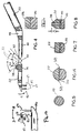
- A preferred embodiment of the invention is shown in the attached drawings, wherein:
- Fig. 1 is a perspective view of one side of the inventive toothbrush with the twisted wire brush in place;
- Fig. 2 is a perspective view of the opposite side of the toothbrush of Fig. 1;
- Fig. 3 shows the toothbrush handle without the twisted wire brush and with the locking retainer in a half open, half closed position;
- Fig. 4 is a side elevation partly in cross section, of the toothbrush as it appears when it emerges from the mold;
- Figs. 5-8 are cross-sections of the handle (without the brush) taken along lines 5-5; 6-6; 7-7; and 8-8, respectively, of Figs. 1 and 11;
- Fig. 9 is a perspective view of a push button latch mechanism; and
- Fig. 10 is a side elevation of the same push button latch mechanism.
- Fig. 11 is a perspective view of one side of the invention toothbrush handle with the twisted wire brush in place;
- Fig. 12 is a perspective view of the opposite side of the toothbrush handle of Fig. 11;
- Fig. 13 shows the toothbrush handle without the twisted wire brush and with the locking retainer in a half open, half closed position;
- Fig. 14 is cross-sections of the handle (without the brush) taken along lines 15-15 of Fig. 11.
- The inventive toothbrush is best seen in Figs. 1-4, as comprising
handle 20 having a locking retainer orcap 22 joined thereto by a double living hinge at 24. A twisted wire brush is seen at 26. When thelocking retainer 22 is closed over thehandle 20, the brush is firmly locked in place. - The exterior contours of the handle with the
locking retainer 22 closed over it are generally smooth with a blended curve so that there are no rough or projecting members which may catch or feel rough to the cheek or gum tissue. There is no need to provide any thumb nail notches or catches in order to facilitate an opening of the locking retainer since there is a novel push button opening mechanism. - The
double living hinge 24 includes a member 30 (Fig. 4) having a generally triangular cross section with a 90° apex angle and joined on one side to thehandle 20 by athin membrane 32 and joined on the other side to thelocking retainer 22 by athin membrane 34. Thethin membranes locking retainer 22 and handle 20 pivot relative to each other. Themembranes roots 33 of angles A, B by radiusing a mold at about 0.0127 cm (0.005-inch). The opposite side of the handle has two sharp indentations, as at 35, which together formtriangular member 30 and which define the undersides ofliving hinges - The
locking retainer 22 has a projecting chimney like member 35 with ahole 36 formed therein for receiving the stem ST of a twisted wire brush. The outer end of thehole 36 is chamfered or beveled at 38 in order to form a funnel shaped opening for guiding, directing, and receiving the end of the twisted wire brush, to facilitate an insertion thereof. Therefore, wire stem ST projects throughhole 36 to be bent over to lie in thegroove 40. - A
groove 40 is formed preferably in thehandle 20 at a location which is aligned with thehole 36. Thehole 36 andgroove 40 may also be at reversed locations in a slightly redesigned handle. The end of the wire stem ST engages theretainer 22 and is guided to bend and entergroove 40. The twisted wire brush stem ST is thus trapped automatically ingroove 40 when thelocking retainer 22 is closed, (swung in direction C). - When the
locking retainer 22 is locked in a closed position, the wire stem ST is located and locked in position within both thehole 36 and thegroove 40. At this time the wire stem ST is bent to have a somewhat L-shape, with one arm of the "L" locked ingroove 40 and the other arm of the "L" passing through thehole 36. The brush is on the opposite end of the stem arm which passes throughhole 36. - The locking
retainer 22 includes an upstanding latch 44 (Fig. 9). A corresponding keeper hole 46 (Fig. 3) is positioned in thehandle 20 at a point which thelatch 42 engages as the lockingretainer 22 swings from an open to a closed position. Once thelatch 42 clears the far side of thekeeper hole 46, the lockingretainer 22 is locked into position. As seen in Figs. 2, 9 thelatch edge 44 on the top oflatch 42 and at the far end ofkeeper hole 36 is a double cam which both helps latch and acts as a push button which may be pushed in order to help initiate an opening of the retainer. - The action of the
latch 42 may be best understood from a review of Fig. 10.Latch 42 comprises a shaft topped by a double cam formed by twobeveled surfaces keeper hole 46. The first cam orbeveled surface 47 causes the shaft to flex in direction E as it encounters the perimeter of thekeeper hole 46. The memory of the plastic is such that afterlatch 44 passes throughkeeper hole 46, thelatch 42 returns in direction D, engages and locks over the far edge of the handle 20 (Fig. 2) at the perimeter ofkeeper hole 46. - When the user wishes to release the locking
retainer 22, he holds handle 20 in his hand and presses againstsurface 45, preferably with his thumb nail. As shown in Fig. 10, the downward pressure of the user's thumb nail acts on the second cam orbeveled surface 45 to exert a downward force F1 against the top of the shaft. This downward force acts on the cam formed by slopingtop 45 oflatch 42 to produce a horizontal vector F2 which flexes the shaft in direction E. As the shaft so flexes, thelatch 42 moves away from the capture position over the far side of thehandle 20 and passes through thekeeper hole 46, thus releasing the lockingretainer 22. It should be noted that the back of thelatch 42 has a slanted relief area R which enables the latch shaft to move back and forth in directions C,E, while in thekeeper hole 46. - The construction of the toothbrush handle may become more apparent from a study of Figs. 5-8, which are four cross sections taken at locations identified in Fig. 1. As shown in Fig. 5, above the locking retainer 22 (section line 5-5), the handle is simply a solid piece of molded plastic, of any suitable geometric configuration (here circular cross-section).
- At the latching end (section 6-6), the locking retainer 22 (Fig. 6) and the handle together form a smooth and substantially uninterrupted contour which does not irritate the gum, cheek or other soft tissue inside the mouth. That is, since the
latch 42 opens with a push button action, it is not necessary to provide an opening or thumb nail catch at the parting line betweenhandle 20 and lockingretainer 22. Such a catch might irritate the soft mouth tissue for people. - Further down the handle (section 7-7) toward the hinged
end 24, the locking retainer 22 (Fig. 7) and handle 20 have substantially the same dimensions to continue the smooth irritation free contour. At this point, thegroove 40 forms a locking area for receiving the end of the twisted wire stem ST when the lockingretainer 22 is latched in a closed position. Still further down the handle (Section 8-8), the retainer is formed into a chimney 37 or extension having a height H which further helps stabilize the twisted wire stem ST. Preferably, the height H extends far enough to reach the bristles of the brush, thus lessening any tendency for the wire stem to bend, at random, during the use thereof. - The embodiment shown by Figs. 11-14 has a similar structure. We use the same numerals to define the same parts. These parts will not be redescribed except for generally.
- The interdental toothbrush handle of Figs. 11-14 has a
handle 20, a lockingretainer 22 joined thereto by a double living hinge at 24 and atwisted wire brush 26. When theretainer 22 is closed over thehandle 20, the brush is firmly locked in place. - The
handle 20 is undercut at 50 in order to give an entrance for a thumb nail to lift theretainer 22 away from thehandle 20 for replacing the twisted wire brush. - As shown in Fig. 13, an
optional Rib 41 may be formed onretainer 22 at a position which enters thegroove 40, in order to trap the twisted wire brush stem. Therefore, if a wire stem projects throughhole 36 at a time when theretainer 22 is closed, (swing in direction C), the end of the stem enters and bends as it slides along thegroove 40. - The
retainer 22 includes anupstanding latching knob 52 having anenlargement 54 thereon. The correspondingkeeper hole 46 is positioned in thehandle 20 at a point which the knob engages as the retainer swings from an open to a closed position. Theenlargement 54 causes a friction fit as it passes through thekeeper hole 46. Once the enlargement clears the far side of the keeper hole, the retainer is locked into position. As seen in Fig. 2, theenlargement 54 on the top ofknob 52 and at the far end ofkeeper hole 46 acts as a push button which may be pushed in order to help initiate an opening of the retainer. - The construction of the toothbrush handle may become more apparent from a study of Figs. 5, 7, 8 and 14 which are four cross sections taken at locations identified in Fig. 11. As shown in Fig. 5, the handle above the retainer (section line 5-5) is simply a solid piece of molded plastic, of any suitable geometric configuration (here circular cross-section).
- At the latching end (section 14-14), the retainer 22 (Fig. 14) is wide then the handle is the area where the handle is undercut at 28. This provides shoulders 58, 58 which may be caught by a thumb nail to further help open the retainer.
- Further down the handle (section 7-7) toward the hinged
end 24, the retainer 22 (Fig. 7) and handle 20 have substantially the same dimensions to form a smooth contour. At this point, thegroove 40 becomes a hole for receiving the end of the twisted wire stem when theretainer 22 is latched in a closed position. Not shown in Fig. 7 is the optional rib 41 (Fig. 13). If shown, therib 41 would fill the top half of the groove 40 (Fig. 7). - Further down the handle (Section 8-8), the retainer is formed into a chimney or extension having a height D which further helps stabilize the twisted wire stem. Preferably, the distance D extends far enough to reach the bristles of the brush, thus lessening any tendency for the wire stem to bend, at random, during the use thereof.
- Those who are skilled in the art will readily perceive how to modify the invention.
Claims (11)
- An interdental toothbrush handle for holding a twisted wire brush, the handle having an elongated handle member (20) with a retainer (22) hinged to the end thereof, the retainer and the handle member having a complementary latch and keeper, the latch is a latching knob (42) and the keeper is a keeper hole (46), the latch entering the keeper when the retainer is swung on the hinge (24) to a closed position on the handle member, a groove (40) formed on the handle member, a retainer hole (36), the retainer hole having a dimension for receiving and holding the stem of a twisted wire brush (26), and the groove being so positioned that when the retainer is in a closed position it extends from the retainer hole towards the latch knob, characterised in that the retainer (22) and the handle member (20) are unitary with each other, and the retainer hole is formed in the retainer (22) near the hinged end.
- The handle of claim 1 wherein the positions and dimensions of the retainer hole (36) and groove (40) are such that a stem (ST) of a twisted wire brush (26) projecting through the retainer hole (36) automatically bends and fits into the groove (40) as the retainer (22) is closed over and latched to the handle (20).
- The handle of claim 1 or 2 wherein the retainer has a protrusion (38) which extends outwardly therefrom to form a somewhat chimney-like extension (35) of the retainer hole (36) for stabilizing and reinforcing the stem (ST) of the wire brush (26).
- The handle of claim 1, 2, or 3 wherein one of the retainer (22) and handle (20) has an undercut region (50) which enables an entrance of a thumb nail to lift the retainer (22) off the handle.
- The handle of any one of claims 1-4 wherein the end of the latching knob (42) protrudes beyond the handle (20) when the retainer (22) and handle (20) are in a latched position, the protruding end forming a push button for opening the retainer relative to the handle.
- The handle of any one of claims 1-5 wherein the hinged end has a member (30) with a triangular cross section separating two living hinges (32,34) for joining the member to the handle (20) and to the retainer (22) respectively.
- The handle of any one of claims 1-6 wherein a rib (41) formed on the retainer or handle opposite the groove (40) for fitting into the groove and helping lock the twisted wire stem (ST) in place.
- The handle of any one of claims 1-7 wherein the retainer (22) closes over the handle (20) and in longitudinal alignment therewith.
- The handle of any one of claims 1-8 wherein the protruding end of the latch has a cam surface forming a push button for opening the retainer relative to the handle when a downward pressure is applied thereto.
- The handle of any one of claims 1-9 wherein the latch is a cantilever shaft projecting from the retainer, the back of the shaft having a slanted relief area (R) which enables the shaft to move back and forth within the keeper hole (46).
- The handle of claims 1-10 wherein the contours on the top of the latch has two substantially planar surfaces (45,47), one of the two planar surfaces forming a cam for guiding the latch into a latched position, and the other of the two planar surfaces forming a cam surface (45) for unlatching the latch responsive to the downward pressure.
Applications Claiming Priority (4)
| Application Number | Priority Date | Filing Date | Title |
|---|---|---|---|
| US07/475,724 US5027467A (en) | 1990-02-06 | 1990-02-06 | Toothbrush |
| US475724 | 1990-02-06 | ||
| US07/575,229 US5201091A (en) | 1990-02-06 | 1990-08-30 | Toothbrush |
| US575229 | 1990-08-30 |
Publications (2)
| Publication Number | Publication Date |
|---|---|
| EP0441597A1 EP0441597A1 (en) | 1991-08-14 |
| EP0441597B1 true EP0441597B1 (en) | 1995-05-10 |
Family
ID=27044909
Family Applications (1)
| Application Number | Title | Priority Date | Filing Date |
|---|---|---|---|
| EP91300936A Expired - Lifetime EP0441597B1 (en) | 1990-02-06 | 1991-02-05 | Interdental toothbrush handle |
Country Status (17)
| Country | Link |
|---|---|
| US (1) | US5201091A (en) |
| EP (1) | EP0441597B1 (en) |
| JP (1) | JPH0640845B2 (en) |
| KR (1) | KR960010615B1 (en) |
| AR (1) | AR248220A1 (en) |
| AT (1) | ATE122217T1 (en) |
| AU (1) | AU637865B2 (en) |
| CA (1) | CA2035788C (en) |
| CH (1) | CH686812A5 (en) |
| DE (1) | DE69109511T2 (en) |
| ES (1) | ES2024372A6 (en) |
| FR (1) | FR2657760B1 (en) |
| GB (1) | GB2240507B (en) |
| HK (1) | HK1001322A1 (en) |
| IL (1) | IL97141A (en) |
| IT (1) | IT1244700B (en) |
| NZ (1) | NZ237022A (en) |
Families Citing this family (12)
| Publication number | Priority date | Publication date | Assignee | Title |
|---|---|---|---|---|
| US5347675A (en) * | 1990-02-06 | 1994-09-20 | John O. Butler Company, Inc. | Toothbrush |
| FR2705018B1 (en) * | 1994-04-12 | 1996-01-19 | Butler John O Co | Toothbrush. |
| US5435033A (en) * | 1994-07-18 | 1995-07-25 | Millner; Don E. | Interdental toothcleaner holder |
| DE19701891C1 (en) | 1997-01-21 | 1998-06-10 | Rueb F A Holding Gmbh | Tooth cleaning device with a handle |
| US5896615A (en) * | 1997-04-28 | 1999-04-27 | Colgate-Palmolive Company | Interdental brush |
| EP1163861A1 (en) | 2000-06-16 | 2001-12-19 | Tepe Munhygienprodukter AB | Toothbrush |
| CA2639269A1 (en) | 2007-09-03 | 2009-03-03 | T.A.G. Oral Health Technologies Inc. | Locking mechanism |
| CN103040420B (en) * | 2011-10-17 | 2015-11-25 | 杨雅菁 | Foldable duster |
| TW201340926A (en) * | 2012-04-13 | 2013-10-16 | Ya-Jing Yang | Automatically foldable length-variable duster handle |
| USD767900S1 (en) * | 2015-03-03 | 2016-10-04 | LeedTech Resources Company, LLC | Interdental brush |
| EP3364818B1 (en) | 2015-10-22 | 2019-07-17 | Colgate-Palmolive Company | Oral care implement |
| US20250262039A1 (en) * | 2024-02-16 | 2025-08-21 | Dental Holdings LLC | Oral quadrent isolating suction device |
Family Cites Families (16)
| Publication number | Priority date | Publication date | Assignee | Title |
|---|---|---|---|---|
| CH175973A (en) * | 1934-03-08 | 1935-03-31 | Studer Babette | Brush with an adjustable handle. |
| US2556500A (en) * | 1947-11-13 | 1951-06-12 | Jack C Levine | Toothbrush |
| US3559226A (en) * | 1968-05-31 | 1971-02-02 | Univ Alabama Medical Center Fo | Tooth brush for interproximal areas |
| US3909050A (en) * | 1974-10-15 | 1975-09-30 | Anthony P Vicendese | Cabinet safety latch |
| DE2723643C3 (en) * | 1977-05-25 | 1981-07-30 | Bosch-Siemens Hausgeräte GmbH, 7000 Stuttgart | Closure device for a removable cover flap of a housing opening on a household appliance |
| US4222143A (en) * | 1979-03-16 | 1980-09-16 | John O. Butler Company | Interproximal brush handle |
| FR2457657A1 (en) * | 1979-05-30 | 1980-12-26 | Celluloid Sa | TOILET KIT, FOR EXAMPLE FOLDABLE AND CONDITIONABLE TOOTHBRUSH |
| US4319377A (en) * | 1980-08-25 | 1982-03-16 | John O. Butler Company | Interproximal toothbrush |
| US4478005A (en) * | 1982-12-27 | 1984-10-23 | General Electric Company | Removable integrally molded closure |
| US4572223A (en) * | 1983-09-12 | 1986-02-25 | Dentool, Inc. | Dental brush holder and assembly |
| CH663717A5 (en) * | 1984-10-25 | 1988-01-15 | Curaden Ag | DEVICE FOR CLEANING THE DENTAL SPACES. |
| US4710996A (en) * | 1986-08-12 | 1987-12-08 | John O. Butler Company | Interdental brush handle |
| US4780923A (en) * | 1987-11-30 | 1988-11-01 | The Gillette Company | Interproximal brush device having hinged brush retainer cap |
| US4805252A (en) * | 1987-10-13 | 1989-02-21 | John O. Butler Company | Toothbrush |
| US4850074A (en) * | 1988-05-18 | 1989-07-25 | Stewart Klevan | Folding toothbrush |
| DE3832694C3 (en) * | 1988-09-27 | 1996-04-25 | Geka Brush Georg Karl Gmbh | Replacement application device for oral hygiene |
-
1990
- 1990-08-30 US US07/575,229 patent/US5201091A/en not_active Expired - Lifetime
-
1991
- 1991-02-04 IL IL9714191A patent/IL97141A/en not_active IP Right Cessation
- 1991-02-05 NZ NZ237022A patent/NZ237022A/en unknown
- 1991-02-05 DE DE69109511T patent/DE69109511T2/en not_active Expired - Lifetime
- 1991-02-05 EP EP91300936A patent/EP0441597B1/en not_active Expired - Lifetime
- 1991-02-05 GB GB9102444A patent/GB2240507B/en not_active Expired - Lifetime
- 1991-02-05 AT AT91300936T patent/ATE122217T1/en not_active IP Right Cessation
- 1991-02-06 ES ES9100306A patent/ES2024372A6/en not_active Expired - Lifetime
- 1991-02-06 KR KR1019910001999A patent/KR960010615B1/en not_active Expired - Fee Related
- 1991-02-06 JP JP3035129A patent/JPH0640845B2/en not_active Expired - Lifetime
- 1991-02-06 AU AU70822/91A patent/AU637865B2/en not_active Expired
- 1991-02-06 CH CH00359/91A patent/CH686812A5/en not_active IP Right Cessation
- 1991-02-06 CA CA002035788A patent/CA2035788C/en not_active Expired - Lifetime
- 1991-02-06 IT ITMI910290A patent/IT1244700B/en active IP Right Grant
- 1991-02-06 AR AR91318998A patent/AR248220A1/en active
- 1991-02-06 FR FR919101568A patent/FR2657760B1/en not_active Expired - Lifetime
-
1998
- 1998-01-19 HK HK98100411A patent/HK1001322A1/en not_active IP Right Cessation
Also Published As
| Publication number | Publication date |
|---|---|
| CH686812A5 (en) | 1996-07-15 |
| GB2240507A (en) | 1991-08-07 |
| JPH0640845B2 (en) | 1994-06-01 |
| IL97141A (en) | 1994-06-24 |
| IL97141A0 (en) | 1992-05-25 |
| AU637865B2 (en) | 1993-06-10 |
| IT1244700B (en) | 1994-08-08 |
| EP0441597A1 (en) | 1991-08-14 |
| GB9102444D0 (en) | 1991-03-20 |
| CA2035788A1 (en) | 1991-08-07 |
| AR248220A1 (en) | 1995-07-12 |
| FR2657760B1 (en) | 1992-07-10 |
| GB2240507B (en) | 1993-12-22 |
| DE69109511T2 (en) | 1996-01-25 |
| ES2024372A6 (en) | 1992-02-16 |
| CA2035788C (en) | 1996-12-03 |
| FR2657760A1 (en) | 1991-08-09 |
| AU7082291A (en) | 1991-08-15 |
| HK1001322A1 (en) | 1998-06-12 |
| KR960010615B1 (en) | 1996-08-06 |
| ITMI910290A1 (en) | 1992-08-06 |
| JPH0523215A (en) | 1993-02-02 |
| ITMI910290A0 (en) | 1991-02-06 |
| KR910015265A (en) | 1991-09-30 |
| NZ237022A (en) | 1993-07-27 |
| US5201091A (en) | 1993-04-13 |
| DE69109511D1 (en) | 1995-06-14 |
| ATE122217T1 (en) | 1995-05-15 |
Similar Documents
| Publication | Publication Date | Title |
|---|---|---|
| CA2035788C (en) | Interdental toothbrush handle | |
| US4780923A (en) | Interproximal brush device having hinged brush retainer cap | |
| US5934295A (en) | Dental hygiene system | |
| US4222143A (en) | Interproximal brush handle | |
| US5435033A (en) | Interdental toothcleaner holder | |
| US5934762A (en) | Oral hygiene devices and manufacturing methods therefor | |
| AU647087B2 (en) | Interproximal brush | |
| US5027467A (en) | Toothbrush | |
| CA1298944C (en) | Interdental brush | |
| JP2525873Y2 (en) | Reciprocating movable device of movable member | |
| CZ103694A3 (en) | Automatically adjustable toothbrush with three heads | |
| IE920653A1 (en) | Toothbrush having handle jointed to brush head by¹non-pinching flexible twin beam structure | |
| US5758382A (en) | Interdental brush handle | |
| CA2120871C (en) | Toothbrush | |
| US5333346A (en) | Toothbrush | |
| JPH09121942A (en) | Interdental brush | |
| JP3124807U (en) | Dental brushing instrument | |
| AU607736B2 (en) | Interproximal brush device having hinged brush retainer cap | |
| KR101697244B1 (en) | Toothbrush | |
| KR102583176B1 (en) | Tongue cleaner | |
| KR0146935B1 (en) | Interdental brush | |
| JPS6132560Y2 (en) | ||
| KR200245173Y1 (en) | tooth brush |
Legal Events
| Date | Code | Title | Description |
|---|---|---|---|
| PUAI | Public reference made under article 153(3) epc to a published international application that has entered the european phase |
Free format text: ORIGINAL CODE: 0009012 |
|
| AK | Designated contracting states |
Kind code of ref document: A1 Designated state(s): AT BE DE NL SE |
|
| 17P | Request for examination filed |
Effective date: 19920131 |
|
| 17Q | First examination report despatched |
Effective date: 19931104 |
|
| GRAA | (expected) grant |
Free format text: ORIGINAL CODE: 0009210 |
|
| AK | Designated contracting states |
Kind code of ref document: B1 Designated state(s): AT BE DE NL SE |
|
| REF | Corresponds to: |
Ref document number: 122217 Country of ref document: AT Date of ref document: 19950515 Kind code of ref document: T |
|
| REF | Corresponds to: |
Ref document number: 69109511 Country of ref document: DE Date of ref document: 19950614 |
|
| PLBE | No opposition filed within time limit |
Free format text: ORIGINAL CODE: 0009261 |
|
| STAA | Information on the status of an ep patent application or granted ep patent |
Free format text: STATUS: NO OPPOSITION FILED WITHIN TIME LIMIT |
|
| 26N | No opposition filed | ||
| PGFP | Annual fee paid to national office [announced via postgrant information from national office to epo] |
Ref country code: AT Payment date: 20100120 Year of fee payment: 20 Ref country code: DE Payment date: 20100226 Year of fee payment: 20 Ref country code: BE Payment date: 20100223 Year of fee payment: 20 |
|
| PGFP | Annual fee paid to national office [announced via postgrant information from national office to epo] |
Ref country code: NL Payment date: 20100223 Year of fee payment: 20 |
|
| PGFP | Annual fee paid to national office [announced via postgrant information from national office to epo] |
Ref country code: SE Payment date: 20100226 Year of fee payment: 20 |
|
| REG | Reference to a national code |
Ref country code: DE Ref legal event code: R071 Ref document number: 69109511 Country of ref document: DE |
|
| REG | Reference to a national code |
Ref country code: NL Ref legal event code: V4 Effective date: 20110205 |
|
| BE20 | Be: patent expired |
Owner name: JOHN O. *BUTLER CY Effective date: 20110205 |
|
| EUG | Se: european patent has lapsed | ||
| PG25 | Lapsed in a contracting state [announced via postgrant information from national office to epo] |
Ref country code: NL Free format text: LAPSE BECAUSE OF EXPIRATION OF PROTECTION Effective date: 20110205 |
|
| PG25 | Lapsed in a contracting state [announced via postgrant information from national office to epo] |
Ref country code: DE Free format text: LAPSE BECAUSE OF EXPIRATION OF PROTECTION Effective date: 20110205 |