EP0441407B1 - System for positioning an object - Google Patents
System for positioning an object Download PDFInfo
- Publication number
- EP0441407B1 EP0441407B1 EP91101824A EP91101824A EP0441407B1 EP 0441407 B1 EP0441407 B1 EP 0441407B1 EP 91101824 A EP91101824 A EP 91101824A EP 91101824 A EP91101824 A EP 91101824A EP 0441407 B1 EP0441407 B1 EP 0441407B1
- Authority
- EP
- European Patent Office
- Prior art keywords
- target
- acceleration
- velocity
- positioning
- time
- Prior art date
- Legal status (The legal status is an assumption and is not a legal conclusion. Google has not performed a legal analysis and makes no representation as to the accuracy of the status listed.)
- Expired - Lifetime
Links
Images


Classifications
-
- G—PHYSICS
- G11—INFORMATION STORAGE
- G11B—INFORMATION STORAGE BASED ON RELATIVE MOVEMENT BETWEEN RECORD CARRIER AND TRANSDUCER
- G11B5/00—Recording by magnetisation or demagnetisation of a record carrier; Reproducing by magnetic means; Record carriers therefor
- G11B5/48—Disposition or mounting of heads or head supports relative to record carriers ; arrangements of heads, e.g. for scanning the record carrier to increase the relative speed
- G11B5/54—Disposition or mounting of heads or head supports relative to record carriers ; arrangements of heads, e.g. for scanning the record carrier to increase the relative speed with provision for moving the head into or out of its operative position or across tracks
- G11B5/55—Track change, selection or acquisition by displacement of the head
- G11B5/5521—Track change, selection or acquisition by displacement of the head across disk tracks
- G11B5/5526—Control therefor; circuits, track configurations or relative disposition of servo-information transducers and servo-information tracks for control thereof
- G11B5/553—Details
- G11B5/5547—"Seek" control and circuits therefor
-
- G—PHYSICS
- G11—INFORMATION STORAGE
- G11B—INFORMATION STORAGE BASED ON RELATIVE MOVEMENT BETWEEN RECORD CARRIER AND TRANSDUCER
- G11B21/00—Head arrangements not specific to the method of recording or reproducing
- G11B21/02—Driving or moving of heads
-
- B—PERFORMING OPERATIONS; TRANSPORTING
- B41—PRINTING; LINING MACHINES; TYPEWRITERS; STAMPS
- B41J—TYPEWRITERS; SELECTIVE PRINTING MECHANISMS, i.e. MECHANISMS PRINTING OTHERWISE THAN FROM A FORME; CORRECTION OF TYPOGRAPHICAL ERRORS
- B41J19/00—Character- or line-spacing mechanisms
- B41J19/18—Character-spacing or back-spacing mechanisms; Carriage return or release devices therefor
Definitions
- the present invention relates to a system for positioning at high speed a transducer such as magnetic head, optical head and print head etc. and more specifically to a positioning control system which has improved accuracy of positioning.
- a storage apparatus such as magnetic disk apparatus and optical disk apparatus executes so-called head seek operation for moving the head to the target track position from the current track position on the disk by controlling an actuator mounting the head.
- head seek operation for moving the head to the target track position from the current track position on the disk by controlling an actuator mounting the head.
- data writing or reading operation is carried out trough the head.
- recording such as printing is carried out by moving and positioning the print head to the target position from the current position.
- Fig. 1 is a sectional view indicating schematic structure of an ordinary magnetic disk apparatus of the prior art providing rotary actuator as it is disclosed in "Acceleration Feedforward Control For Head Positioning In Magnetic Disk Drives", The International Conference on ADVANCED MECHATRONICS, K.Aruga et al., Fujitsu Laboratories Ltd., 1989.
- an enclosure 111 supports rotatably, for example, three sheets of magnetic disks 112 through a spindle 113 and these disks 112 are rotated at a constant speed, for example, of 3600 rpm with a spindle motor 114.
- the magnetic head 115 is attached to a head arm 117 through a support spring means 116 and is positioned to the designated track of the magnetic disk 112.
- the rotary actuator is composed of a rotary member 118 which fixes the head arm 117 and is rotatably supported by the enclosure 111 and a positioning motor for rotating the rotary member, for example, a voice coil motor 119, and rotates the magnetic head 115 for predetermined angle around the rotating axis of rotating member 118.
- a magnetic disk apparatus for high density recording uses a closed loop servo control means for controlling such actuator.
- This closed loop servo control means detects the current position of magnetic head from the original position thereof by reading servo information on the magnetic disk with a magnetic head, also calculates distance to the designated track position from the current position, drives the positioning motor based on such distance and positions the magnetic head to the designated track.
- Fig. 2 schematically shows an example of such servo control system as it was proposed by JBM in 1988.
- 115A denotes servo head for positioning
- 115B data read/write head
- 121 rotary actuator
- 122, 123 amplifier
- 124 demodulator for demodulation servo signal
- 125 AD converter
- 126 DA converter
- 127 read/write control circuit
- 129 main controller consisting of microprocessor.
- the same reference numerals are used for indicating the disk rotating system and head positioning system.
- This servo control system is formed by a closed loop of servo head 115A - amplifier 122 - demodulator 124 - AD converter 125 - main controller 129 - DA converter 126 - amplifier 123 - rotary actuator 121.
- the functions of these elements are already known and only the control of actuator in relation to the present invention will be explained here.
- the main controller 129 comprises a memory to store tabulated data indicating a curve of target velocity corresponding to the moving distance of head.
- a target velocity curve which is calculated on the off-line basis and is shown in Fig. 3, is used as a function of the number of tracks in the distance up to the target track position from the current track position.
- This target speed curve which is described in "Digital Control of Dynamic Systems”; Franklin, Powell, Workman, Addison- Wesley Publishing Company; 2nd edition; 1990, shows the deceleration characteristic for stopping the head at the target track position from a certain velocity thereof and the actuator is controlled corresponding to error between the actual velocity of head and the target velocity curve.
- the positioning control in such prior art realizes control of head by giving the target velocity curve which indicates the deceleration characteristic and basically does not conduct control of acceleration. Accordingly, the high speed seek operation requires supply of heavy current to the voice coil motor of actuator at the time of starting seek and coincidence between acutal velocity and target velocity curve within a short period of time, and also requires large change of drive current. Moreover, change of drive current also becomes large when acceleration mode is switched to the deceleration mode. Therefore, harmonics in the drive current increase deriving vibration due to resonance of mechanical part of actuator including magnetic head and decrease the accuracy of the head positioning. Therefore, it has been difficult to realize the high speed seek operation
- the present invention is characterized by controlling position, velocity and acceleration of the transducer minimizing a cost function by indicating such state values as the polynomials of the time.
- the present invention comprises a drive such as actuator for realizing positioning by moving the transducer such as magnetic head and an arithmetic controller for controlling such driver with digital arithmetics.
- the target position, target velocity and target acceleration are indicated as the polynomials of time on the basis of the acceleration and deceleration patterns which minimize square integration value of differential value of acceleration of the transducer and the target position, target velocity and target acceleration of each time are computed in the arithmetic controller using such polynomials.
- This arithmetic controller outputs of at least one error between the target position, target velocity as the result of arithmetics and position, velocity of each sample period of the transducer, adds such position error or velocity error and the target acceleration as a result of such arithmetic, controls the driver with this added signal and thereby positions the transducer to the target position.
- the control means computes the above values in order to control the drive means on the basis of the target acceleration, which is corrected by the difference between the target and the actual velocity and/or position of the object, in order to minimize the total square value of the differential acceleration of the object during the seek time along the seek distance.
- numeral 1 denotes transducer (apparatus to be controlled) such as magnetic head, optical head and print head, etc.; 2, driver for moving the transducer 1 for the positioning; 3, arithmetic controller for controlling the driver 2 with digital arithmetics; 4, data table consisting of memory.
- transducer apparatus to be controlled
- driver for moving the transducer 1 for the positioning
- arithmetic controller for controlling the driver 2 with digital arithmetics
- data table consisting of memory.
- the target position, target velocity and target acceleration are indicated with polynomials of time based on the basis of acceleration and deceleration patterns which minimize the square integral value of differential value of the acceleration of the transducer 1 and controls the driver 2 in accordance with difference between the arithmetic result of each sample time and the arithmetic controller 3 computes the target position, target velocity and target acceleration of each sample period using such polynomials, outputs at least one error between target position, target velocity as a result of such arithmetic and position, velocity of each sample period of transducer 1, moreover adds the position error or velocity error and the target acceleration as a result of such arithmetic and controls the driver 2 with the added output.
- the acceleration and deceleration profiles are set for minimizing square value of differential value of acceleration.
- A, B and X are defined as follows when the mass of transducer 1 is m.
- the boundary condition is as follows when the designed seek time is assumed as T and the moving distance as a.
- the target position X1, target velocity X2 and target acceleration X3 of the positioning control for minimizing cost function J is indicated as follows.
- X 1 -60a(0.1(t/T) 5 - 0.25(t/T) 4 + (1/6)(t/T) 3 )
- X 1 -60a((0.5(t/T) 4 - (t/T) 3 + 0.5(t/T) 2 ) /T)
- X 3 -60a((2(t/T) 3 - 3(t/T) 2 + (t/T)) /T 2 )
- the equations (5), (6) and (7) are computed in the arithmetic controller 3 for each sample period (Ts) and the driver 2 is controlled to follow up the position, velocity and acceleration of the actual transducer.
- the gain of target velocity and gain of target acceleration are indicated in the equations (6), (7) as the designed seek time T corresponding to the seek distance a or its inverse value 1/T or ratio (Ts/T) is previously stored in the data table 4 and the target velocity gain and target acceleration gain can be computed using the values obtained by retrieving the data table based on the moving distance a immediately before the seek operation.
- the time t from start of seek operation of transducer 1 is normalized by the designed seek time T and the target acceleration, target velocity and target position can be computed using this normalized time t/T.
- the normalized position x/a of each sample period can be computed by the distance X from start of the seek operation of transducer 1 and the designed seek distance. Then the normalizing time can also be obtained by retrieving another data table that stores relationship between the normalized position x/a and normalized time t/T.
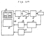
- Figs. 5(A), (B), (C) are block diagrams of the head positioning control of the magnetic disk apparatus as the preferred embodiment of the present invention.
- 11 denotes magnetic head consisting of a data head and a servo head; 12, voice coil motor for driving actuator loading magnetic heads; 13, amplifier; 14, DA converter; 15, position signal demodulating circuit; 16, AD converter; 17, counter; 18, digital arithmetic circuit; 19, arithmetic circuit for addition, subtraction, multiplication and division; 20, memory; 20a, 20b, first and second data tables.
- the arithmetic circuit 19 comprises, in a concrete example of Fig. 5(B), a circuit 190 for computing position of magnetic head, a circuit 191 for estimating speed of the head, a circuit 192 for normalizing the position signal, a circuit 193 for computing seek distance, a circuit 194 for computing the normalized time, a circuit 195 for computing the target velocity, a circuit 196 for computing the target acceleration, a switch circuit 197 for switching the normalized time signal, a circuit 198 for respectively computing the gains of target velocity and the target acceleration, a circuit 199 for computing error signal between the current velocity and target velocity and a circuit 200 for adding the velocity error signal and target acceleration signal.
- the current position of magnetic head on the magnetic disk can be obtained by the position computing circuit 190 using the accumulated value of track pulse obtained from a counter 17 and deviation from the track center of magnetic head obtained from an AD converter 16.
- head velocity can be obtained by inputting the current position signal and a drive signal of voice coil motor to the velocity estimation circuit 191 and then computing such input signals with the ordinary velocity estimation algorithm for general purpose.
- velocity estimation algorithm is described, for example, in "Digital Control of Dynamic Systems", 2nd edition, Addison-Wesley, 1990, pp. 703-749 by G. Franklin, J. Powell and M.L. Workman.
- the current position signal (current track position) thus obtained is input to the seek distance arithmetic circuit 193 which computes difference between the current track and the target track designated from the host controller.
- this seek distance a is computed at the time of starting the seek operation and is constant during the seek operation. Relationship between this seek distance a and the designated seek time T is preset and stored, for example, in the first data table 20a.
- the gains (A,B in the figure) of the target velocity and the target acceleration of equation (8) explained above can be obtained only with multiplication conducted in the gain arithmetic circuit 198 by storing the inverse number 1/T of the designed seek time T to table 20a.
- a ratio Ts/T of the sample period T s and designed seek time T can also be stored in the first data table 20a.
- the second data table 20b is capable of storing relationship between the normalized time (t/T) and normalized position (X/a).
- the cost function J may be expressed by the following equation.
- the target position X1, target velocity X2 and target acceleration X3 for positioning control which minimizes the cost function J are respectively indicated by the expressions of fifth, fourth and third orders.
- the target velocity X2 is indicated as follows.
- X 2 C 4 (t/T) 4 + C 3 (t/T) 3 + C 2 (t/T) 2 + C 1 (t/T) + C 0
- the arithmetic circuits 196, 197 obtain the target velocity X2 and target acceleration X3 for each sample period using the equations (6), (7), (8) and outputs a drive output signal to cause the magnetic head 11 to follow such states.
- the arithmetic processing may be simplified by retrieving the first and second data tables 20a, 20b in the arithmetic process.
- the normalized time t/T explained above may be determined by a couple of methods during the seek operation in the present invention. In the one method, it is determined by the arithmetic circuit 194 explained above. In this case, t/T is computed using 1/T which is an output of the first data table 20a and the clock of digital arithmetic circuit. In the other method, the second data table 20b is used. Here, the second data table stores the relationship between the normalized position X/a and normalized time t/T and outputs the normalized time t/T from the normalized position X/a obtained by the position signal normalizing circuit 192 explained above.
- the normalized time t/T output from the arithmetic circuit 194 is used for acceleration mode of seek operation while the normalized time t/T stored in the second data table 20b is used for the deceleration mode.
- the switch circuit 197 is used for switching use of the normalized times.
- t/T of each sample period can be obtained only by accumulating the values read from the first data table 20a.
- the current distance X is divided by the seek distance a for each sample period and the normalized time t/T can be obtained from the second data table 20a based on such value X/a (normalized position). Accordingly, the target position X1, target velocity X2 and target acceleration X3 can be computed using such normalized time t/T for each sample period.
- the drive signal for the voice coil motor 12 of actuator is obtained from an adder circuit 200 for adding an output (FF signal) of the target acceleration arithmetic circuit 196 and an output of an error signal arithmetic circuit 199.
- the error signal arithmetic circuit 199 obtains difference between an output (target velocity) of the target velocity arithmetic circuit 195 and an output (current velocity) of the velocity estimation circuit 192 and outputs a velocity error signal.
- an inverse value 1/T of the seek time T is obtained on the basis of seek distance a immediately before (at the time of starting) the seek operation, the gains (-60a/T, -60a/T) of target velocity and target acceleration of equation (8) are computed, the normalized time t/T in the equations (5) to (7) is computed for each sample time by multiplying the time passage t after start of seek time the inverse value 1/T of the seek time, and the target position X1, target X2 and target acceleration X3 can be computed trough multiplication of constants based on such values.
- This motor drive signal is then converted to an analog signal, namely to the drive current by the DA converter 14.
- This drive current is amplified by an amplifier 13 and is then supplied to the voice coil motor 12. Thereby, the voice coil motor 12 is driven and the magnetic head 11 is positioned to the target track.
- the digital arithmetic circuit 18 may be formed by a digital signal processor including a multiplier.
- An external memory is also provided and thereby the first and second data tables 20a, 20b can also be formed.
- Fig. 6 is a flowchart for explaining operations of preferred embodiment.
- This flowchart indicates 16 processing steps (1) to (16) in the digital arithmetic circuit 18.
- the target speed gain and target acceleration gain (FF feed forward gain) are computed with the equation (8) by start of seek operation.
- the designed seek time T or its inverse number 1/T is obtained by retrieving the first data table 20a and the target velocity gain and target acceleration gain can be computed using this value 1/T.
- the current position information of head 11 is input for each sample period and in the step (3), the acceleration period or deceleration period is decided. This decision is based on the current position information and the former half section from the boundary which is equal to 1/2 of the seek distance a is set as the acceleration section, while the latter half section as the deceleration section.
- t/T is computed in the step (4) and the target velocity is computed by the equation (6) in the step (5).
- the target acceleration signal (Feed Forward FF signal) is computed by the equation (7) in the step (10)
- estimated velocity value actual velocity of head
- velocity error target velocity - estimated velocity value is computed in the step (12)
- output signal velocity error + FF signal is computed in the step (13).
- the actuator drive signal is output to the amplifier 13 and the drive current is supplied to the voice coil motor 12 from the amplifier 13.
- end of seek operation is decided in the step (15). If seek is not completed, operation skips to the step (2).
- the tracking control of step (16) starts.
- X/a is computed in the step (6) and the normalized time t/T is retrieved from the second data table based on the normalized position X/a in the step (7).
- the target speed is computed by the equation (6) in the step (8) based on such data and operation skips to the step (10).
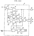
- Fig. 5(C) shows a block diagram of the arithmetic circuit when both target velocity and target position are used.
- the arithmetic circuit of Fig. 5(C) is different from that of Fig. 5(B) in such points that an arithmetic circuit 201 for computing the target position is added and the gain arithmetic circuit 198 is also used to compute the gain (C in the figure) of the target position.
- the error signal arithmetic circuit 199 respectively computes error between the target velocity and current velocity and error between the target position and current position and input these error signals to the adder circuit 200. Moreover the adder circuit 200 adds this position error signal, velocity error signal and target acceleration signal and the added signal of these is used as the voice coil motor drive signal.
- Fig. 7 is a diagram for explaining normalized position, velocity and acceleration of magnetic head.
- the normalized time t/T is plotted on the horizontal axis, while the normalized position X/a, normalized velocity and normalized acceleration on the vertical axis, respectively.
- the curve al indicates the target normalized position; the curve a2, the target normalized velocity and the curve a3, the target normalized acceleration.
- Fig. 8 shows relationship between the seek distance a of the magnetic head and inverse number 1/T of designed seek time T with a curve b.
- the seek distance a corresponds to a number of tracks which is equal to difference between the current track and the target track of the magnetic head 11.
- the inverse number 1/T of the designed seek time can be obtained by looking up such relationship in the first data table 20a. Therefore, the target velocity gain, target acceleration gain and normalized time t/T can easily be obtained.
- Fig. 9 indicates relationship between the normalized distance X/a and normalized time t/T.
- the acceleration period is set in the range 0 to 0.5 of the normalized time t/T, while the deceleration period in the range 0.5 to 1.0 of t/T. Accordingly, in the acceleration period, the normalized distance X/a is ranged from 0 to 0.5, while it is ranged from 0.5 to 1 in the deceleration period.
- the normalized time t/T may be obtained from the normalized distance X/a in each sample period by looking up such relationship in the second data table 20b. Therefore, the target position, target velocity and target acceleration can easily be computed.
- Fig. 10 is a diagram indicating the acceleration characteristic of magnetic head.
- the vertical axis indicates acceleration m/s and horizontal axis indicates time ms .
- the curve a shows an example of acceleration characteristic by the embodiment of the present invention and the curve b shows acceleration characteristic of the prior art.
- the embodiment of the present invention realizes smooth positioning control of magnetic head since the peak value of acceleration is smaller than that of prior art and it also changes more smoothly.
- the velocity and acceleration control may be realized for actuator without derivation of vibration of magnetic head.
- the magnetic head can also be positioned to the target track accurately at a high speed.
- positioning control may also be executed with simplified algorithm by digital arithmetics.
- a preferred embodiment applied to the magnetic disk apparatus has been explained above, but moreover the present invention can also be applied to positioning control of optical head of disk apparatus and that of print head of printer. In addition, this embodiment can surely be applied to mechanical positioning of an object to be controlled to the target position.
Landscapes
- Control Of Position Or Direction (AREA)
- Moving Of Head For Track Selection And Changing (AREA)
Description
- The present invention relates to a system for positioning at high speed a transducer such as magnetic head, optical head and print head etc. and more specifically to a positioning control system which has improved accuracy of positioning.
- A storage apparatus such as magnetic disk apparatus and optical disk apparatus executes so-called head seek operation for moving the head to the target track position from the current track position on the disk by controlling an actuator mounting the head. When the head is positioned to the designated target track position, data writing or reading operation is carried out trough the head. Moreover, even in a recording apparatus such as serial printer, X-Y plotter, etc., recording such as printing is carried out by moving and positioning the print head to the target position from the current position.
- Fig. 1 is a sectional view indicating schematic structure of an ordinary magnetic disk apparatus of the prior art providing rotary actuator as it is disclosed in "Acceleration Feedforward Control For Head Positioning In Magnetic Disk Drives", The International Conference on ADVANCED MECHATRONICS, K.Aruga et al., Fujitsu Laboratories Ltd., 1989.
- In Fig. 1, an
enclosure 111 supports rotatably, for example, three sheets ofmagnetic disks 112 through aspindle 113 and thesedisks 112 are rotated at a constant speed, for example, of 3600 rpm with aspindle motor 114. Moreover, themagnetic head 115 is attached to ahead arm 117 through a support spring means 116 and is positioned to the designated track of themagnetic disk 112. The rotary actuator is composed of arotary member 118 which fixes thehead arm 117 and is rotatably supported by theenclosure 111 and a positioning motor for rotating the rotary member, for example, avoice coil motor 119, and rotates themagnetic head 115 for predetermined angle around the rotating axis of rotatingmember 118. - A magnetic disk apparatus for high density recording uses a closed loop servo control means for controlling such actuator. This closed loop servo control means detects the current position of magnetic head from the original position thereof by reading servo information on the magnetic disk with a magnetic head, also calculates distance to the designated track position from the current position, drives the positioning motor based on such distance and positions the magnetic head to the designated track. Fig. 2 schematically shows an example of such servo control system as it was proposed by JBM in 1988.
- In Fig. 2, 115A denotes servo head for positioning; 115B, data read/write head; 121, rotary actuator; 122, 123, amplifier; 124, demodulator for demodulation servo signal; 125, AD converter; 126, DA converter; 127, read/write control circuit; 128, motor control circuit; 129, main controller consisting of microprocessor. The same reference numerals are used for indicating the disk rotating system and head positioning system. This servo control system is formed by a closed loop of
servo head 115A - amplifier 122 - demodulator 124 - AD converter 125 - main controller 129 - DA converter 126 - amplifier 123 -rotary actuator 121. The functions of these elements are already known and only the control of actuator in relation to the present invention will be explained here. - The
main controller 129 comprises a memory to store tabulated data indicating a curve of target velocity corresponding to the moving distance of head. In concrete, a target velocity curve which is calculated on the off-line basis and is shown in Fig. 3, is used as a function of the number of tracks in the distance up to the target track position from the current track position. This target speed curve which is described in "Digital Control of Dynamic Systems"; Franklin, Powell, Workman, Addison- Wesley Publishing Company; 2nd edition; 1990, shows the deceleration characteristic for stopping the head at the target track position from a certain velocity thereof and the actuator is controlled corresponding to error between the actual velocity of head and the target velocity curve. Therefore, since there is a large velocity error when the head seeking operation is started, when the voice coil motor of actuator is driven with maximum capability of the driving force and the actual velocity of head coincides with the target velocity curve, the deceleration control is then carried out in accordance with the target velocity curve. - Such control is generally realized with a structure introducing the analog circuit but the structure which realizes such control with digital circuit is also proposed.
- The positioning control in such prior art realizes control of head by giving the target velocity curve which indicates the deceleration characteristic and basically does not conduct control of acceleration. Accordingly, the high speed seek operation requires supply of heavy current to the voice coil motor of actuator at the time of starting seek and coincidence between acutal velocity and target velocity curve within a short period of time, and also requires large change of drive current.
Moreover, change of drive current also becomes large when acceleration mode is switched to the deceleration mode. Therefore, harmonics in the drive current increase deriving vibration due to resonance of mechanical part of actuator including magnetic head and decrease the accuracy of the head positioning. Therefore, it has been difficult to realize the high speed seek operation - For this condition, it is thought to control the head velocity for both acceleration and deceleration of seek but it is difficult to realize such control because the analog circuit structure is complicated. Moreover, it can also be thought to realize such control with digital circuit, but it is far from easy to realize such control without derivation of vibration even when the head speed is controlled for both acceleration and deceleration.
- As a system for controlling speed and acceleration of head in both acceleration and deceleration of seek operation in order to prevent the problem explained above, namely vibration and noise of actuator means in the seek operation of head, two kinds of methods, the U.S. Patent No. 4,796,112 by M. Mizukami et. al. and the U.S. Patent No. 4,937,689 by Jay. S. Sunnyvale et. al. are proposed. These methods employ the trapezoidal wave as the acceleration and deceleration current (acceleration) in order to suppress vibration. Therefore, these methods are required to determine the shape of trapezoidal acceleration in accordance with each seek stroke. In other words, the times until the preset trapezoidal acceleration reaches the maximum value and minimum value and the time for switching the acceleration to deceleration must be set in detail.
Particularly it is essential in the U.S. Patent No. 4,796,112 to set the ratio of upper side and bottom side of trapezoidal wave in accordance with the seek stroke. Accordingly, these methods have the disadvantage that the circuit structure or algorithm are very complicated for both analog and digital circuits. - It is a main object of the present invention to provide a high speed positioning system for realizing acceleration and deceleration controls of actuator without generation of vibration in the transducer such as magnetic head, optical head and print head apparatus.
- It is another object of the present invention to provide a positioning control system for transducer by simple algorithm utilizing digital arithmetic circuit.
- Briefly, the present invention is characterized by controlling position, velocity and acceleration of the transducer minimizing a cost function by indicating such state values as the polynomials of the time.
- In more detail, the present invention comprises a drive such as actuator for realizing positioning by moving the transducer such as magnetic head and an arithmetic controller for controlling such driver with digital arithmetics. The target position, target velocity and target acceleration are indicated as the polynomials of time on the basis of the acceleration and deceleration patterns which minimize square integration value of differential value of acceleration of the transducer and the target position, target velocity and target acceleration of each time are computed in the arithmetic controller using such polynomials. This arithmetic controller outputs of at least one error between the target position, target velocity as the result of arithmetics and position, velocity of each sample period of the transducer, adds such position error or velocity error and the target acceleration as a result of such arithmetic, controls the driver with this added signal and thereby positions the transducer to the target position.
- In further more detail, according to the invention, a system for positioning an object along a seek distance during a seek time is provided, comprising means for measuring the actual motion of the object, drive means for moving the object, and control means controlling the drive means in that the control means predetermine a target motion and control the drive means on the basis of at least the difference between the target motion and the actual motion of the object, wherein the control means arithmetically compute the target acceleration X₃ according to


- Other objects and characteristics of the present invention will be well unterstood from explanation about a preferred embodiment described with reference to the accompanying drawings.
-
- Fig. 1 is a schematic sectional view of a conventional magnetic disk apparatus comprising an ordinary rotary actuator;
- Fig. 2 and Fig. 3 are diagrams for explaining servo control for head positioning in the magnetic disk apparatus of the prior art;
- Fig. 4 is a diagram for explaining the basic structure of the present invention;
- Figs. 5(A), 5(B), 5(C) are a block diagram for indicating a structure for head positioning control in the magnetic disk apparatus to which the present invention is applied;
- Fig. 6 is a flowchart for explaining operation of an embodiment of the present invention shown in Fig. 5;
- Fig. 7 is a diagram for explaining position, velocity and acceleration of magnetic head;
- Fig. 8 shows a relation curve between the seek distance and inverse value of seek time of the magnetic head;
- Fig. 9 shows a relation curve between normalized distance and normalized time; and
- Fig. 10 is an acceleration characteristic curve of magnetic head.
- Prior to explanation about a preferred embodiment of the present invention, the basic structure of the present invention will be first explained with reference to Fig. 4.
- Namely, in Fig. 4,
numeral 1 denotes transducer (apparatus to be controlled) such as magnetic head, optical head and print head, etc.; 2, driver for moving thetransducer 1 for the positioning; 3, arithmetic controller for controlling thedriver 2 with digital arithmetics; 4, data table consisting of memory. In the present invention, the target position, target velocity and target acceleration are indicated with polynomials of time based on the basis of acceleration and deceleration patterns which minimize the square integral value of differential value of the acceleration of thetransducer 1 and controls thedriver 2 in accordance with difference between the arithmetic result of each sample time and thearithmetic controller 3 computes the target position, target velocity and target acceleration of each sample period using such polynomials, outputs at least one error between target position, target velocity as a result of such arithmetic and position, velocity of each sample period oftransducer 1, moreover adds the position error or velocity error and the target acceleration as a result of such arithmetic and controls thedriver 2 with the added output. - Namely, the acceleration and deceleration profiles are set for minimizing square value of differential value of acceleration. In this case, the cost function J is expressed by the following equation.

- Where, when a drive current of the
driver 2 is assumed as i, u is defined as u = di/dt and the drive current i corresponds to acceleration. The state equation is expressed as
- Here, A, B and X are defined as follows when the mass of
transducer 1 is m.
- The boundary condition is as follows when the designed seek time is assumed as T and the moving distance as a.

- Therefore, the target position X₁, target velocity X₂ and target acceleration X₃ of the positioning control for minimizing cost function J is indicated as follows.


arithmetic controller 3 for each sample period (Ts) and thedriver 2 is controlled to follow up the position, velocity and acceleration of the actual transducer. - Since the gain of target velocity and gain of target acceleration are indicated in the equations (6), (7) as

inverse value 1/T or ratio (Ts/T) is previously stored in the data table 4 and the target velocity gain and target acceleration gain can be computed using the values obtained by retrieving the data table based on the moving distance a immediately before the seek operation. - The time t from start of seek operation of
transducer 1 is normalized by the designed seek time T and the target acceleration, target velocity and target position can be computed using this normalized time t/T. - The normalized position x/a of each sample period can be computed by the distance X from start of the seek operation of
transducer 1 and the designed seek distance. Then the normalizing time can also be obtained by retrieving another data table that stores relationship between the normalized position x/a and normalized time t/T. - A preferred embodiment of the present invention in accordance with such basic structure will be explained in detail.
- Figs. 5(A), (B), (C) are block diagrams of the head positioning control of the magnetic disk apparatus as the preferred embodiment of the present invention. In this figure, 11 denotes magnetic head consisting of a data head and a servo head; 12, voice coil motor for driving actuator loading magnetic heads; 13, amplifier; 14, DA converter; 15, position signal demodulating circuit; 16, AD converter; 17, counter; 18, digital arithmetic circuit; 19, arithmetic circuit for addition, subtraction, multiplication and division; 20, memory; 20a, 20b, first and second data tables.
- The
arithmetic circuit 19 comprises, in a concrete example of Fig. 5(B), acircuit 190 for computing position of magnetic head, acircuit 191 for estimating speed of the head, acircuit 192 for normalizing the position signal, acircuit 193 for computing seek distance, acircuit 194 for computing the normalized time, acircuit 195 for computing the target velocity, acircuit 196 for computing the target acceleration, aswitch circuit 197 for switching the normalized time signal, acircuit 198 for respectively computing the gains of target velocity and the target acceleration, acircuit 199 for computing error signal between the current velocity and target velocity and acircuit 200 for adding the velocity error signal and target acceleration signal. - The current position of magnetic head on the magnetic disk can be obtained by the
position computing circuit 190 using the accumulated value of track pulse obtained from acounter 17 and deviation from the track center of magnetic head obtained from anAD converter 16. In this case, head velocity can be obtained by inputting the current position signal and a drive signal of voice coil motor to thevelocity estimation circuit 191 and then computing such input signals with the ordinary velocity estimation algorithm for general purpose. Such velocity estimation algorithm is described, for example, in "Digital Control of Dynamic Systems", 2nd edition, Addison-Wesley, 1990, pp. 703-749 by G. Franklin, J. Powell and M.L. Workman. - The current position signal (current track position) thus obtained is input to the seek distance
arithmetic circuit 193 which computes difference between the current track and the target track designated from the host controller. However, this seek distance a is computed at the time of starting the seek operation and is constant during the seek operation. Relationship between this seek distance a and the designated seek time T is preset and stored, for example, in the first data table 20a. In this case, the gains (A,B in the figure) of the target velocity and the target acceleration of equation (8) explained above can be obtained only with multiplication conducted in the gainarithmetic circuit 198 by storing theinverse number 1/T of the designed seek time T to table 20a. A ratio Ts/T of the sample period Ts and designed seek time T can also be stored in the first data table 20a. Meanwhile, the second data table 20b is capable of storing relationship between the normalized time (t/T) and normalized position (X/a). - As explained above, the cost function J may be expressed by the following equation.

- Where, u = di/dt and the drive current i is proportional to the acceleration. Therefore, the cost function J becomes equal to a value obtained by integrating the square value of the differential value of acceleration.
- The target position X₁, target velocity X₂ and target acceleration X₃ for positioning control which minimizes the cost function J are respectively indicated by the expressions of fifth, fourth and third orders. For instance, when constants are assumed as C₀ to C₄, the target velocity X₂ is indicated as follows.

- Such equations of target position, target velocity and target acceleration may be solved as indicated by the equations (5), (6) and (7) with the boundary conditions of X₁ = a, X₂ = 0, X₃ = 0 for t = 0 and X₁ = 0, X₂ = 0 and X₃ = 0 for t = T.
- The
arithmetic circuits magnetic head 11 to follow such states. The arithmetic processing may be simplified by retrieving the first and second data tables 20a, 20b in the arithmetic process. - The normalized time t/T explained above may be determined by a couple of methods during the seek operation in the present invention. In the one method, it is determined by the
arithmetic circuit 194 explained above. In this case, t/T is computed using 1/T which is an output of the first data table 20a and the clock of digital arithmetic circuit. In the other method, the second data table 20b is used. Here, the second data table stores the relationship between the normalized position X/a and normalized time t/T and outputs the normalized time t/T from the normalized position X/a obtained by the positionsignal normalizing circuit 192 explained above. - For the target acceleration
arithmetic circuit 196, the normalized time t/T output from thearithmetic circuit 194 is used. Moreover, for the target velocityarithmetic circuit 195, two kinds of normalized times explained above are selectively used. Namely, the normalized time t/T output from thearithmetic circuit 194 is used for acceleration mode of seek operation while the normalized time t/T stored in the second data table 20b is used for the deceleration mode. Theswitch circuit 197 is used for switching use of the normalized times. - Moreover, in case Ts/T for seek distance a is stored in the first data table 20a, t/T of each sample period can be obtained only by accumulating the values read from the first data table 20a.
- Moreover, in case the relationship between the normalized time t/T and normalized position X/a is stored in the second data table 20b, the current distance X is divided by the seek distance a for each sample period and the normalized time t/T can be obtained from the second data table 20a based on such value X/a (normalized position). Accordingly, the target position X₁, target velocity X₂ and target acceleration X₃ can be computed using such normalized time t/T for each sample period.
- The drive signal for the
voice coil motor 12 of actuator is obtained from anadder circuit 200 for adding an output (FF signal) of the target accelerationarithmetic circuit 196 and an output of an error signalarithmetic circuit 199. In this case, the error signalarithmetic circuit 199 obtains difference between an output (target velocity) of the target velocityarithmetic circuit 195 and an output (current velocity) of thevelocity estimation circuit 192 and outputs a velocity error signal. - For instance, an
inverse value 1/T of the seek time T is obtained on the basis of seek distance a immediately before (at the time of starting) the seek operation, the gains (-60a/T, -60a/T) of target velocity and target acceleration of equation (8) are computed, the normalized time t/T in the equations (5) to (7) is computed for each sample time by multiplying the time passage t after start of seek time theinverse value 1/T of the seek time, and the target position X₁, target X₂ and target acceleration X₃ can be computed trough multiplication of constants based on such values. - This motor drive signal is then converted to an analog signal, namely to the drive current by the
DA converter 14. This drive current is amplified by anamplifier 13 and is then supplied to thevoice coil motor 12. Thereby, thevoice coil motor 12 is driven and themagnetic head 11 is positioned to the target track. - The digital
arithmetic circuit 18 may be formed by a digital signal processor including a multiplier. An external memory is also provided and thereby the first and second data tables 20a, 20b can also be formed. - Fig. 6 is a flowchart for explaining operations of preferred embodiment. This flowchart indicates 16 processing steps (1) to (16) in the digital
arithmetic circuit 18. In the first step (1), the target speed gain and target acceleration gain (FF feed forward gain) are computed with the equation (8) by start of seek operation. In this case, since the seek distance a can be detected from the number of tracks which is equal to difference between the current track position and the target track position of themagnetic head 11, the designed seek time T or itsinverse number 1/T is obtained by retrieving the first data table 20a and the target velocity gain and target acceleration gain can be computed using thisvalue 1/T. - In the step (2), the current position information of
head 11 is input for each sample period and in the step (3), the acceleration period or deceleration period is decided. This decision is based on the current position information and the former half section from the boundary which is equal to 1/2 of the seek distance a is set as the acceleration section, while the latter half section as the deceleration section. - In the case of acceleration section, t/T is computed in the step (4) and the target velocity is computed by the equation (6) in the step (5).
Moreover, the target acceleration signal (Feed Forward FF signal) is computed by the equation (7) in the step (10), estimated velocity value (actual velocity of head) is computed in the step (11), velocity error = target velocity - estimated velocity value is computed in the step (12) and output signal = velocity error + FF signal is computed in the step (13). In the next step (14), the actuator drive signal is output to theamplifier 13 and the drive current is supplied to thevoice coil motor 12 from theamplifier 13. Thereafter, end of seek operation is decided in the step (15). If seek is not completed, operation skips to the step (2). When seek is completed, the tracking control of step (16) starts. - On the other hand, in the deceleration period, X/a is computed in the step (6) and the normalized time t/T is retrieved from the second data table based on the normalized position X/a in the step (7). The target speed is computed by the equation (6) in the step (8) based on such data and operation skips to the step (10).
- In the arithmetic circuit of Fig. 5(B) explained above, only the target velocity is used as the embodiment but the present invention is not limited only to such embodiment. That is, the target position can also be used in addition to such target velocity and only the target position may also be used. Fig 5(C) shows a block diagram of the arithmetic circuit when both target velocity and target position are used. The arithmetic circuit of Fig. 5(C) is different from that of Fig. 5(B) in such points that an
arithmetic circuit 201 for computing the target position is added and the gainarithmetic circuit 198 is also used to compute the gain (C in the figure) of the target position.
Therefore, in this case, the error signalarithmetic circuit 199 respectively computes error between the target velocity and current velocity and error between the target position and current position and input these error signals to theadder circuit 200. Moreover theadder circuit 200 adds this position error signal, velocity error signal and target acceleration signal and the added signal of these is used as the voice coil motor drive signal. - Fig. 7 is a diagram for explaining normalized position, velocity and acceleration of magnetic head. In this diagram, the normalized time t/T is plotted on the horizontal axis, while the normalized position X/a, normalized velocity and normalized acceleration on the vertical axis, respectively. The curve al indicates the target normalized position; the curve a2, the target normalized velocity and the curve a3, the target normalized acceleration.
- Namely, the seek operation of magnetic head is completed at the normalized time t/T = 1. Therefore, the acceleration time is set in the
range 0 to 0.5 of normalized time t/T and the deceleration time is set in the range 0.5 to 1 of t/T. The maximum normalizing acceleration in the acceleration period is generated at the normalized time
- Fig. 8 shows relationship between the seek distance a of the magnetic head and
inverse number 1/T of designed seek time T with a curve b. The seek distance a corresponds to a number of tracks which is equal to difference between the current track and the target track of themagnetic head 11. When the seek distance a is given, theinverse number 1/T of the designed seek time can be obtained by looking up such relationship in the first data table 20a. Therefore, the target velocity gain, target acceleration gain and normalized time t/T can easily be obtained. - Fig. 9 indicates relationship between the normalized distance X/a and normalized time t/T. The acceleration period is set in the
range 0 to 0.5 of the normalized time t/T, while the deceleration period in the range 0.5 to 1.0 of t/T. Accordingly, in the acceleration period, the normalized distance X/a is ranged from 0 to 0.5, while it is ranged from 0.5 to 1 in the deceleration period. The normalized time t/T may be obtained from the normalized distance X/a in each sample period by looking up such relationship in the second data table 20b. Therefore, the target position, target velocity and target acceleration can easily be computed. - Fig. 10 is a diagram indicating the acceleration characteristic of magnetic head. The vertical axis indicates acceleration m/s and horizontal axis indicates time ms . The curve a shows an example of acceleration characteristic by the embodiment of the present invention and the curve b shows acceleration characteristic of the prior art. In case the positioning of magnetic head is completed within the period of about 5 ms, the embodiment of the present invention realizes smooth positioning control of magnetic head since the peak value of acceleration is smaller than that of prior art and it also changes more smoothly.
- According to the embodiment of the present invention, the velocity and acceleration control may be realized for actuator without derivation of vibration of magnetic head. Moreover, the magnetic head can also be positioned to the target track accurately at a high speed. Moreover, such positioning control may also be executed with simplified algorithm by digital arithmetics.
- A preferred embodiment applied to the magnetic disk apparatus has been explained above, but moreover the present invention can also be applied to positioning control of optical head of disk apparatus and that of print head of printer. In addition, this embodiment can surely be applied to mechanical positioning of an object to be controlled to the target position.
- The embodiment of present invention will be limited only by the scope of the claim thereof.
Claims (8)
- A system for positioning an object along a seek distance (a) during a seek time (T),
comprisingmeans for measuring the actual motion of said object (1);drive means (2) for moving said object (1); andcontrol means (3) controlling said drive means (2) in that said control means (3)predetermine a target motion and control said drive means (2) on the basis of at least the difference between said target motion and said actual motion of said object (1),
characterized in thatsaid control means (3) arithmetically compute the target acceleration (X₃) according toin order to control said drive means (2) on the basis of said target acceleration, which is corrected by the difference between said target and the actual velocity and/or position of said object (1), in order to minimize the total square value of the differential acceleration of said object (1) during said seek time (T) along said seek distance (a).


- A system for positioning an object according to claim 2,
characterized bya data table (4) storing data indicating said designated seek time (T) corresponding to said seek distance (a) of said object (1) or the inverse (1/T) of said designated seek time (T) or the ratio (Ts/T) of said designated seek time (T) and a sample period (Ts),wherein the target velocity gain and target acceleration gain are determined using said data obtained by retrieving said data table (4). - A system for positioning an object according to claim 1 or 2,
characterized in thatthe period (t) from start to end of positioning of said object (1) is normalized by said designated seek time (T) for each sample period in said control means (3),said target acceleration (X₃) is computed by using said normalized time (t/T), andsaid target acceleration (X3) is multiplied with said target acceleration gain and the result of the multiplication is applied to a drive signal to be supplied to said drive means (2). - A system for positioning an object according to anyone of claims 1 - 3,
characterized in thata data table is provided for storing the data which indicates said normalized time (t/T) and a normalized position (X/a),said target position (X₁), target velocity (X₂) and target acceleration (X₃) are determined by computing said normalized position (X/a) from the current position (X) and said seek distance (a) of said object (1), andsaid normalized time (t/T) is retrieved from said table based on said normalized position (X/a). - A system for positioning an object according to anyone of claims 1 - 4,
characterized in thatsaid object (1) is composed of a magnetic head which is movable on a magnetic disk, andsaid drive means (2) is composed of an actuator loading said magnetic head and a positioning motor for driving said actuator. - A system for positioning an object according to anyone of claims 1 - 4,
characterized in thatsaid object (1) is composed of an optical head which is movable on an optical disk, andsaid drive means (2) is composed of an actuator loading said optical head and a positioning motor for driving said actuator. - A system for positioning an object according to anyone of claims 1 - 4,
characterized in thatsaid object (1) is composed of a print head which is movable on a printing sheet, andsaid drive means (2) is composed of an actuator loading said print head and a positioning motor for driving said actuator. - A system for positioning a magnetic disk apparatus consisting of an actuator for moving and positioning a magnetic head (11) to a designated track on a magnetic disk and control means (17, 18, 19, 20) for controlling a drive motor (12) of said actuator on the basis of at least the difference between a target motion and the actual motion of said magnetic disk apparatus,
characterized in thatsaid control means (17, 18, 19, 20) is of arithmetic type and comprisesfirst (201), second (195) and third (196) arithmetic circuits for respectively computing the target position, target velocity and target acceleration of each sample period in time with polynomials of time of the target position, target velocity and target acceleration generated based on acceleration and deceleration patterns which minimize a square value of a differential value of an acceleration of said magnetic haead (11),fourth (190) and fifth (191) arithmetic circuits for estimating position and velocity of each sample period of said magnetic head (11),a sixth arithmetic circuit (199) for computing at least one error between said target position and target velocity output from said first and second arithmetic circuits (201, 195) and said position and velocity output from said fourth and fifth arithmetic circuits (190, 191), anda seventh arithmetic circuit (200) for adding a target acceleration signal output from said third arithmetic circuit (196) and a position error signal output from said sixth arithmetic circuit (199) or a velocity error signal output from said sixth arithmetic circuit (199) and then outputting a control signal for said drive motor (12) of said actuator.
Applications Claiming Priority (2)
| Application Number | Priority Date | Filing Date | Title |
|---|---|---|---|
| JP28197/90 | 1990-02-09 | ||
| JP2028197A JP2657561B2 (en) | 1990-02-09 | 1990-02-09 | Positioning control method |
Publications (2)
| Publication Number | Publication Date |
|---|---|
| EP0441407A1 EP0441407A1 (en) | 1991-08-14 |
| EP0441407B1 true EP0441407B1 (en) | 1996-01-03 |
Family
ID=12241949
Family Applications (1)
| Application Number | Title | Priority Date | Filing Date |
|---|---|---|---|
| EP91101824A Expired - Lifetime EP0441407B1 (en) | 1990-02-09 | 1991-02-09 | System for positioning an object |
Country Status (6)
| Country | Link |
|---|---|
| US (1) | US5151639A (en) |
| EP (1) | EP0441407B1 (en) |
| JP (1) | JP2657561B2 (en) |
| KR (1) | KR930009998B1 (en) |
| CA (1) | CA2036024A1 (en) |
| DE (1) | DE69115944T2 (en) |
Families Citing this family (51)
| Publication number | Priority date | Publication date | Assignee | Title |
|---|---|---|---|---|
| JP2697399B2 (en) * | 1991-09-13 | 1998-01-14 | 三菱電機株式会社 | Positioning device and program display method thereof |
| US5291110A (en) * | 1991-10-31 | 1994-03-01 | Integral Peripherals, Inc. | Low acoustic noise seeking method and apparatus |
| DE69227434T2 (en) * | 1991-11-22 | 1999-03-18 | Fujitsu Ltd., Kawasaki, Kanagawa | Position control system |
| JP3758687B2 (en) * | 1992-03-18 | 2006-03-22 | 富士通株式会社 | Electronic device startup control method |
| JPH0631663A (en) * | 1992-07-17 | 1994-02-08 | Fujitsu Ltd | Track control device for profile control robot |
| US5517099A (en) * | 1993-06-15 | 1996-05-14 | International Modern Technologies, Inc. | Method and apparatus for robust integral-pulse control of a servodrive of unknown dynamics |
| JP3513188B2 (en) * | 1993-07-30 | 2004-03-31 | キヤノン株式会社 | Lens system |
| JPH07195784A (en) * | 1993-12-28 | 1995-08-01 | Canon Inc | Driving method of printer |
| US5696647A (en) * | 1994-03-28 | 1997-12-09 | Seagate Technology, Inc. | Method for carrying out seeks in a hard disc drive to limit the generation of acoustic noise including using a slew rate limit |
| JP3444953B2 (en) * | 1994-04-06 | 2003-09-08 | 富士通株式会社 | Drive control device |
| US6084742A (en) * | 1994-04-06 | 2000-07-04 | Fujitsu Limited | Drive control apparatus for a disk drive |
| DE69535162T2 (en) * | 1994-06-07 | 2007-03-08 | Hitachi Global Storage Technologies Japan, Ltd., Odawara | An information recording apparatus and method for controlling it to record / reproduce information by selecting an operation mode |
| KR0135113B1 (en) * | 1994-06-29 | 1998-04-22 | 김광호 | Servo control method and apparatus for disk drive |
| US5675562A (en) * | 1995-03-20 | 1997-10-07 | Fujitsu Limited | Seek control method in optical storage device |
| US5570332A (en) * | 1995-05-25 | 1996-10-29 | Seagate Technology, Inc. | Method for reducing rotational latency in a disc drive |
| JPH0973618A (en) * | 1995-09-07 | 1997-03-18 | Toshiba Corp | Head positioning control system for disk recording and reproducing device, and speed control method suitable for the system |
| JP3875294B2 (en) * | 1995-11-17 | 2007-01-31 | 富士通株式会社 | Disk unit |
| JPH09180387A (en) * | 1995-12-28 | 1997-07-11 | Fujitsu Ltd | Head position demodulating method |
| US6125000A (en) * | 1996-05-21 | 2000-09-26 | Maxtor Corporation | Disk drive seek control system utilizing predicted motion parameter and dynamic trajectory alignment |
| JPH09320061A (en) * | 1996-05-30 | 1997-12-12 | Olympus Optical Co Ltd | Speed control device for head |
| JP3621227B2 (en) * | 1997-03-18 | 2005-02-16 | 株式会社リコー | Motor control method and drive device |
| US6314473B1 (en) | 1998-03-05 | 2001-11-06 | Convolve, Inc. | System for removing selected unwanted frequenices in accordance with altered settings in a user interface of a data storage device |
| CN100456223C (en) * | 1998-03-05 | 2009-01-28 | 康约维公司 | Dynamic system control method |
| US6449117B1 (en) | 1998-07-13 | 2002-09-10 | Seagate Technology Llc | Reducing acoustic noise using a current profile during initial stages of a disc drive seek |
| US6441988B2 (en) * | 1998-10-07 | 2002-08-27 | Samsung Electronics Co., Ltd. | Method and apparatus for reducing acoustic noise in a hard disk drive |
| US7433144B2 (en) | 1999-03-04 | 2008-10-07 | Convolve, Inc. | Dynamic system control method |
| JP2001006304A (en) * | 1999-06-23 | 2001-01-12 | Matsushita Electric Ind Co Ltd | Magnetic disk device |
| US6501613B1 (en) * | 1999-12-15 | 2002-12-31 | Samsung Electronics Co., Ltd. | Generalized Fourier seek method and apparatus for a hard disk drive servomechanism |
| US6549364B1 (en) * | 1999-12-15 | 2003-04-15 | Samsung Electronics Co., Ltd. | Optimization method and apparatus for a generalized fourier seek trajectory for a hard disk drive servomechanism |
| MXPA01013103A (en) * | 2000-04-25 | 2002-06-04 | Koninkl Philips Electronics Nv | A device for encoding decoding n bit source words into corresponding m bit channel words, and vice versa. |
| US6801384B2 (en) | 2000-09-14 | 2004-10-05 | Samsung Electronics Co., Ltd. | Voltage-constrained sinusoidal seek servo in hard disk drives |
| US6744590B2 (en) | 2000-09-14 | 2004-06-01 | Samsung Electronics Co., Inc. | Seek trajectory adaptation in sinusoidal seek servo hard disk drives |
| JPWO2002025389A1 (en) * | 2000-09-19 | 2004-02-12 | 富士通株式会社 | Digital servo control method, digital servo control device, storage device, and head position control method |
| US6578106B1 (en) * | 2000-10-31 | 2003-06-10 | Keen Personal Media, Inc. | Data storage system adapted to select an operational state with corresponding performance levels and acoustic noise levels based on a system profile |
| US6762902B2 (en) | 2000-12-15 | 2004-07-13 | Samsung Electronics Co., Ltd. | Time-varying, non-synchronous disturbance identification and cancellation in a rotating disk storage device |
| US6754036B2 (en) * | 2001-01-29 | 2004-06-22 | Seagate Technology Llc | Automated tuning of disc drive seek profile |
| KR100400036B1 (en) * | 2001-02-22 | 2003-09-29 | 삼성전자주식회사 | Apparatus and method for performing seek-servo routine of hard disk drive |
| US6762571B2 (en) * | 2001-09-21 | 2004-07-13 | Seagate Technology Llc | Sinusoidal feed-forward seek with adaptive acoustic level constraint |
| JP2003077144A (en) * | 2002-07-01 | 2003-03-14 | Fujitsu Ltd | Optical storage device |
| JP2005267762A (en) | 2004-03-19 | 2005-09-29 | Hitachi Global Storage Technologies Netherlands Bv | Magnetic disk device |
| JP2006202368A (en) * | 2005-01-18 | 2006-08-03 | Hitachi Global Storage Technologies Netherlands Bv | Head seek control method in which vibration is suppressed, and rotation recording and reproducing apparatus |
| US7319570B2 (en) | 2005-09-19 | 2008-01-15 | Seagate Technology Llc | Random vibration and shock compensator using a disturbance observer |
| JP2007094952A (en) | 2005-09-30 | 2007-04-12 | Brother Ind Ltd | Drive control device |
| JP4509952B2 (en) * | 2006-03-03 | 2010-07-21 | 東芝ストレージデバイス株式会社 | Control device, disk device, and seek trajectory generation method |
| JP4550764B2 (en) | 2006-04-26 | 2010-09-22 | 東芝ストレージデバイス株式会社 | SEEK CONTROL METHOD, SEEK CONTROL DEVICE, AND DISC DEVICE |
| JP4612603B2 (en) | 2006-09-28 | 2011-01-12 | 東芝ストレージデバイス株式会社 | SEEK CONTROL METHOD, SEEK CONTROL DEVICE, AND MEDIUM STORAGE DEVICE |
| US7479751B2 (en) * | 2007-01-29 | 2009-01-20 | Rockwell Automation Technologies, Inc. | Elimination of unintended velocity reversals in s-curve velocity profiles |
| JP5038998B2 (en) * | 2007-10-26 | 2012-10-03 | 株式会社東芝 | SEEK CONTROL DEVICE AND CONTROL DATA GENERATION METHOD FOR SEEK CONTROL |
| US7486469B1 (en) | 2007-10-31 | 2009-02-03 | Hitachi Global Storage Technologies Netherlands B.V. | Minimizing a mechanical mode excitation utilizing a generated seek trajectory |
| JP5283804B1 (en) | 2012-10-25 | 2013-09-04 | 三菱電機株式会社 | Servo control device |
| US11676629B1 (en) * | 2022-01-14 | 2023-06-13 | Western Digital Technologies, Inc. | Sampled-data polydyne feedforward position control |
Family Cites Families (12)
| Publication number | Priority date | Publication date | Assignee | Title |
|---|---|---|---|---|
| US4137728A (en) * | 1977-04-29 | 1979-02-06 | Vanguard Supreme Machine Corporation | Cam track for a circular knitting machine |
| JPS60124020A (en) * | 1983-12-08 | 1985-07-02 | Fujitsu Ltd | Detecting system of head position in data memory device |
| JPH0682303B2 (en) * | 1985-01-09 | 1994-10-19 | 株式会社ユーエスシー | Moving speed controller |
| JPS6272008A (en) * | 1985-09-25 | 1987-04-02 | Kobe Steel Ltd | Buffer control method for robot |
| JPS6272007A (en) * | 1985-09-25 | 1987-04-02 | Kobe Steel Ltd | Buffer control method for robot |
| US4679103A (en) * | 1986-04-29 | 1987-07-07 | International Business Machines Corporation | Digital servo control system for a data recording disk file |
| JPS637571A (en) * | 1986-06-27 | 1988-01-13 | Nec Corp | Magnetic disk device |
| US4761595A (en) * | 1987-05-01 | 1988-08-02 | General Motors Corporation | Motion control system having adaptive feedforward path tracking |
| US4769583A (en) * | 1987-05-01 | 1988-09-06 | General Motors Corporation | Motion control system with minimum time path generation |
| JPS6443879A (en) * | 1987-08-06 | 1989-02-16 | Ibm | Method and apparatus for control of positioning of head |
| US4914644A (en) * | 1988-09-26 | 1990-04-03 | International Business Machines Corporation | Disk file digital servo control system with coil current modeling |
| JPH07117856B2 (en) * | 1989-03-08 | 1995-12-18 | インターナショナル・ビジネス・マシーンズ・コーポレーション | Estimated positioning system and method |
-
1990
- 1990-02-09 JP JP2028197A patent/JP2657561B2/en not_active Expired - Fee Related
-
1991
- 1991-02-08 US US07/652,822 patent/US5151639A/en not_active Expired - Lifetime
- 1991-02-08 KR KR1019910002158A patent/KR930009998B1/en not_active IP Right Cessation
- 1991-02-08 CA CA002036024A patent/CA2036024A1/en not_active Abandoned
- 1991-02-09 DE DE69115944T patent/DE69115944T2/en not_active Expired - Fee Related
- 1991-02-09 EP EP91101824A patent/EP0441407B1/en not_active Expired - Lifetime
Also Published As
| Publication number | Publication date |
|---|---|
| EP0441407A1 (en) | 1991-08-14 |
| JPH03233609A (en) | 1991-10-17 |
| CA2036024A1 (en) | 1991-08-10 |
| DE69115944D1 (en) | 1996-02-15 |
| US5151639A (en) | 1992-09-29 |
| JP2657561B2 (en) | 1997-09-24 |
| KR930009998B1 (en) | 1993-10-13 |
| KR910015989A (en) | 1991-09-30 |
| DE69115944T2 (en) | 1996-09-19 |
Similar Documents
| Publication | Publication Date | Title |
|---|---|---|
| EP0441407B1 (en) | System for positioning an object | |
| JP2714905B2 (en) | Positioning control device | |
| EP0543654A2 (en) | Positioning control system | |
| JPH07117856B2 (en) | Estimated positioning system and method | |
| EP0302683B1 (en) | A method of, and an apparatus for, controlling the position of a data transducer head | |
| CA1189187A (en) | Servo control of seek operation in magnetic disk drive | |
| US5229896A (en) | Disk drive and method of controlling the same | |
| EP0605239B1 (en) | Information recording and/or reproducing apparatus | |
| JP4365042B2 (en) | Self-tuning model reference type disk drive controller | |
| EP0532238B1 (en) | Tape speed control apparatus | |
| US7006321B2 (en) | Data storage apparatus, rotation control apparatus, and rotation control method | |
| US6873490B2 (en) | Control object positioning using jerk, current and time optimized control profiles | |
| US7609474B2 (en) | Seek control method, seek control device and disk device | |
| JP2606646B2 (en) | State estimator and compensator for positioning control and magnetic disk drive using the same | |
| EP0356939B1 (en) | Device for controlling an access operation of an information recording and reproducing device | |
| EP0989549B1 (en) | Method and apparatus for controlling a voice control motor in a hard disk drive | |
| JPH07287916A (en) | Dual voltages type servo device and method | |
| JPH02144606A (en) | Quick access control system | |
| JPH01286791A (en) | Speed controller | |
| JP2595810B2 (en) | Disk device position control device | |
| JPH056635A (en) | Magnetic disk apparatus | |
| JPS62293577A (en) | Positioning control device for magnetic head | |
| US20040257696A1 (en) | Time linear arrival for velocity mode seeks | |
| JPH04111268A (en) | Velocity controller for data recording and reproducing device | |
| JPH08203225A (en) | Positioning control method for moving body |
Legal Events
| Date | Code | Title | Description |
|---|---|---|---|
| PUAI | Public reference made under article 153(3) epc to a published international application that has entered the european phase |
Free format text: ORIGINAL CODE: 0009012 |
|
| AK | Designated contracting states |
Kind code of ref document: A1 Designated state(s): DE FR GB IT |
|
| 17P | Request for examination filed |
Effective date: 19910813 |
|
| 17Q | First examination report despatched |
Effective date: 19940804 |
|
| GRAA | (expected) grant |
Free format text: ORIGINAL CODE: 0009210 |
|
| AK | Designated contracting states |
Kind code of ref document: B1 Designated state(s): DE FR GB IT |
|
| PG25 | Lapsed in a contracting state [announced via postgrant information from national office to epo] |
Ref country code: IT Free format text: LAPSE BECAUSE OF FAILURE TO SUBMIT A TRANSLATION OF THE DESCRIPTION OR TO PAY THE FEE WITHIN THE PRE;WARNING: LAPSES OF ITALIAN PATENTS WITH EFFECTIVE DATE BEFORE 2007 MAY HAVE OCCURRED AT ANY TIME BEFORE 2007. THE CORRECT EFFECTIVE DATE MAY BE DIFFERENT FROM THE ONE RECORDED.SCRIBED TIME-LIMIT Effective date: 19960103 |
|
| REF | Corresponds to: |
Ref document number: 69115944 Country of ref document: DE Date of ref document: 19960215 |
|
| ET | Fr: translation filed | ||
| PLBE | No opposition filed within time limit |
Free format text: ORIGINAL CODE: 0009261 |
|
| STAA | Information on the status of an ep patent application or granted ep patent |
Free format text: STATUS: NO OPPOSITION FILED WITHIN TIME LIMIT |
|
| 26N | No opposition filed | ||
| REG | Reference to a national code |
Ref country code: GB Ref legal event code: IF02 |
|
| PGFP | Annual fee paid to national office [announced via postgrant information from national office to epo] |
Ref country code: DE Payment date: 20060202 Year of fee payment: 16 |
|
| PGFP | Annual fee paid to national office [announced via postgrant information from national office to epo] |
Ref country code: GB Payment date: 20060208 Year of fee payment: 16 |
|
| PGFP | Annual fee paid to national office [announced via postgrant information from national office to epo] |
Ref country code: FR Payment date: 20060220 Year of fee payment: 16 |
|
| GBPC | Gb: european patent ceased through non-payment of renewal fee |
Effective date: 20070209 |
|
| REG | Reference to a national code |
Ref country code: FR Ref legal event code: ST Effective date: 20071030 |
|
| PG25 | Lapsed in a contracting state [announced via postgrant information from national office to epo] |
Ref country code: DE Free format text: LAPSE BECAUSE OF NON-PAYMENT OF DUE FEES Effective date: 20070901 |
|
| PG25 | Lapsed in a contracting state [announced via postgrant information from national office to epo] |
Ref country code: GB Free format text: LAPSE BECAUSE OF NON-PAYMENT OF DUE FEES Effective date: 20070209 Ref country code: FR Free format text: LAPSE BECAUSE OF NON-PAYMENT OF DUE FEES Effective date: 20070228 |