EP0441402A2 - Image fixing apparatus without crease of fixing film - Google Patents
Image fixing apparatus without crease of fixing film Download PDFInfo
- Publication number
- EP0441402A2 EP0441402A2 EP91101803A EP91101803A EP0441402A2 EP 0441402 A2 EP0441402 A2 EP 0441402A2 EP 91101803 A EP91101803 A EP 91101803A EP 91101803 A EP91101803 A EP 91101803A EP 0441402 A2 EP0441402 A2 EP 0441402A2
- Authority
- EP
- European Patent Office
- Prior art keywords
- film
- heater
- recording material
- image
- crowning
- Prior art date
- Legal status (The legal status is an assumption and is not a legal conclusion. Google has not performed a legal analysis and makes no representation as to the accuracy of the status listed.)
- Granted
Links
Images

Classifications
-
- G—PHYSICS
- G03—PHOTOGRAPHY; CINEMATOGRAPHY; ANALOGOUS TECHNIQUES USING WAVES OTHER THAN OPTICAL WAVES; ELECTROGRAPHY; HOLOGRAPHY
- G03G—ELECTROGRAPHY; ELECTROPHOTOGRAPHY; MAGNETOGRAPHY
- G03G15/00—Apparatus for electrographic processes using a charge pattern
- G03G15/20—Apparatus for electrographic processes using a charge pattern for fixing, e.g. by using heat
- G03G15/2003—Apparatus for electrographic processes using a charge pattern for fixing, e.g. by using heat using heat
- G03G15/2014—Apparatus for electrographic processes using a charge pattern for fixing, e.g. by using heat using heat using contact heat
- G03G15/2064—Apparatus for electrographic processes using a charge pattern for fixing, e.g. by using heat using heat using contact heat combined with pressure
-
- G—PHYSICS
- G03—PHOTOGRAPHY; CINEMATOGRAPHY; ANALOGOUS TECHNIQUES USING WAVES OTHER THAN OPTICAL WAVES; ELECTROGRAPHY; HOLOGRAPHY
- G03G—ELECTROGRAPHY; ELECTROPHOTOGRAPHY; MAGNETOGRAPHY
- G03G15/00—Apparatus for electrographic processes using a charge pattern
- G03G15/20—Apparatus for electrographic processes using a charge pattern for fixing, e.g. by using heat
- G03G15/2003—Apparatus for electrographic processes using a charge pattern for fixing, e.g. by using heat using heat
- G03G15/2014—Apparatus for electrographic processes using a charge pattern for fixing, e.g. by using heat using heat using contact heat
- G03G15/206—Structural details or chemical composition of the pressure elements and layers thereof
-
- G—PHYSICS
- G03—PHOTOGRAPHY; CINEMATOGRAPHY; ANALOGOUS TECHNIQUES USING WAVES OTHER THAN OPTICAL WAVES; ELECTROGRAPHY; HOLOGRAPHY
- G03G—ELECTROGRAPHY; ELECTROPHOTOGRAPHY; MAGNETOGRAPHY
- G03G2215/00—Apparatus for electrophotographic processes
- G03G2215/20—Details of the fixing device or porcess
- G03G2215/2003—Structural features of the fixing device
- G03G2215/2016—Heating belt
- G03G2215/2035—Heating belt the fixing nip having a stationary belt support member opposing a pressure member
- G03G2215/2038—Heating belt the fixing nip having a stationary belt support member opposing a pressure member the belt further entrained around one or more rotating belt support members
-
- G—PHYSICS
- G03—PHOTOGRAPHY; CINEMATOGRAPHY; ANALOGOUS TECHNIQUES USING WAVES OTHER THAN OPTICAL WAVES; ELECTROGRAPHY; HOLOGRAPHY
- G03G—ELECTROGRAPHY; ELECTROPHOTOGRAPHY; MAGNETOGRAPHY
- G03G2215/00—Apparatus for electrophotographic processes
- G03G2215/20—Details of the fixing device or porcess
- G03G2215/2003—Structural features of the fixing device
- G03G2215/2058—Shape of roller along rotational axis
- G03G2215/2061—Shape of roller along rotational axis concave
Definitions
- the present invention relates to an image fixing apparatus usable with an image forming apparatus such as a copying machine or a printer, more particularly to a heat-fixing image fixing apparatus wherein an image is fixed by heat from a heater through a film.
- the recording medium is passed through a nip formed between a heating roller maintained at a predetermined temperature and a pressing or back-up roller having an elastic layer and press-contacted to the heating roller.
- This system however involves the problem that the warming-up period is relatively long until the temperature of the heating roller reaches a predetermined level.
- the members applying the tension to the film is required to be very accurate. If it or they involve variation, the film slacks in the middle of the width with the result of crease of the film.
- the pressing roller presses the film to the heater to form a nip between the film and the pressing roller.
- the recording material in the nip the recording material is creased, or the trailing edge of the recording material is unintentionally raised.
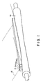
- Figure 1 is a perspective view of an image fixing apparatus according to an embodiment of the present invention.
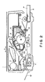
- Figure 2 is a sectional view of an image forming apparatus using the image fixing apparatus of Figure 1.
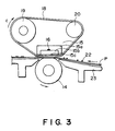
- Figure 3 is a sectional view of an image fixing apparatus according to another embodiment of the present invention.
- Figure 4 is a graph showing a relation between an amount of a heater crowning and an amount of reverse-crowning of a pressing roller.
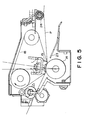
- Figure 5 is a sectional view of an image fixing apparatus according to a further embodiment of the present invention.
- the image forming apparatus comprises an original supporting platen 1 made of transparent material such as glass and reciprocable in the direction a to scan an original. Right below the original carriage, an array of short focus imaging elements is disposed. An original placed on the original carriage is illuminated by an illumination lamp 3, and the reflected light image is projected through a slit and through said array onto a photosensitive drum 4.
- the photosensitive drum rotates in the direction b.
- the photosensitive drum 4 has a zinc oxide photosensitive layer or an organic photoconductor photosensitive layer or the like.
- a charger 5 uniformly charges the surface of the photosensitive drum.
- the drum 4 thus uniformly charged by the charger is exposed to the image light through the array 2, so that an electrostatic latent image is formed.
- the latent image is visualized with a toner made of heat-softening or heat-fusible resin by a developing device.
- a sheet P (recording material) accommodated in a cassette S is fed to the drum 4 by a pick-up roller 7 and registration rollers 8 rotates in synchronism with the image on the photosensitive drum 4.
- the toner image formed on the photosensitive drum 4 is transferred onto the sheet P by a transfer discharger 9. Thereafter, the sheet P is separated from the drum 4 by a known separating means, and is introduced along the conveying guide 10 into an image fixing apparatus 11 where it is subjected to the heat-fixing operation. Then, the sheet is discharged onto the tray 37. After the toner image has been transferred, the residual toner remaining on the photosensitive drum 4 is removed by a cleaner 20.
- an image fixing apparatus 11 comprising a low thermal capacity linear heat-generating element (heater) 15, a film 18 in contact with the heater 15, a pressing or back-up roller 14 for urging the film 18 to the heater 15.
- the pressing roller rotates following the film which is driven.
- Figure 3 is an enlarged sectional view of the image fixing apparatus 11 shown in Figure 2.
- the heater 15 is fixed at least during the fixing operation and comprises an alumina base plate 15b having a thickness of 1.0 mm, a width of 10 mm and a length of 240 mm, for example and made of good thermally conductive material, a holder 15a made of heat insulative material for supporting the alumina base plate 15b, and a heat generating resistor 15c applied on the alumina base plate 15b in a width of 1.0 mm.
- the longitudinal ends of the heater 15 are connected with a power source supplying 100 Vdc pulses at the frequency of 20 msec.
- a temperature sensor 16 is in the form of a thermister for detecting a temperature of the alumina base plate 15b, and the width of the pulse applied to the heat generating resistor is controlled generally within the range of 0.5 - 5 msec so as to the temperature detected by the temperature sensor 16 is constant.
- the temperature of the toner at the point where the film 18 is separated from the recording material 21 is selected to be higher than the glass transition point of the toner, preferably higher than a softening temperature of the toner (ball and ring method).
- the fixing film 18 slides on the heater 15 in the direction indicated by an arrow c, the heater 15 being maintained at a predetermined temperature.
- the fixing film 18, for example, comprises a heat resistive film of polyimide (PI), polyether imide (PEI), polyether sulfone (PES) or perfluoroalkoxy (PFA), having a thickness of 20 microns, and a parting layer made of polytetrafluoroethylene (PTFE) or another fluorinated resin, having a thickness of 10 microns, at least at an image contactable side. It is in the form of an endless belt, for example. Generally, the total thickness of the film is less than 100 microns, preferably not more than 40 microns.
- the fixing film 18 is stretched around a driving roller 19 for driving the film 18 and a follower roller 20 driven by the film 18, and by the driving force and the tension thereby, it is moved without crease in the direction c.
- the pressing roller 19 has a rubber elastic layer made of silicone rubber or the like having a good parting property. It applies pressure to the low thermal capacity linear heater 15 through the fixing film with the total pressure of 4 - 7 kg.
- the unfixed toner image 22 on the recording material P is introduced along an inlet guide 23 into a nip (contact area) between the film 18 and the pressing roller 14.
- the recording material 21 is pressed to the heater 15 through the film by the pressing roller 14 in the nip.
- the side of the recording material 21 that bears the toner image 22 is contacted to the film 18, and the fixed image is provided by the heating.
- the crease of the film is not produced even if there is a slight variation in the parallelism among the driving roller 19, the follower roller 20 and the heater 15.
- the fixing film 18 is tentioned around the driving roller 19, the follower roller 20 and the low thermal capacity linear heater 15. If the longitudinal surface of the heater 15 which is contactable to the film 18 is straight, the tension of the film 18 in the middle part of the length of the heater becomes smaller than the tensions at the opposite ends, due to the variation of the roller or rollers in the cylindricity and straightness and/or due to the central deformation of the roller or rollers when the tension is applied. This results in the tendency of the lateral ends of the film moving toward the longitudinal centers of the heater. Since the film is thin, creases are produced adjacent the lateral center of the film.
- the bottom surface (near the recording material) of the low thermal capacity linear heater 15 is concaved down or crowned in the longitudinal direction. By doing so, the weakening of the tension at the middle of the film is prevented.
- the longitudinal crowning of the heater 15 is such that the holder 15a, the alumina substrate 15b and the heat generating resistor material 15c are all crowned toward the recording material so that the longitudinal crowned portion of the heater 15 is contacted to the film 18.
- the conveying force applied to the recording material is larger at the portion where the nip pressure is large than the position where it is small. Therefore, when the thickness of the recording material is small, the crease may be produced by the force toward the inside in the direction of the width of the film, to the recording material P.
- the pressing roller 14 is reversely crowned in the longitudinal direction to match with the crowning of the heater.
- the recording material can receive the outward forces in the direction of the width of the film, so that the recording material is prevented from creasing.
- the trailing edge rise of the recording material P is too large, the following problem is possible.
- a process cartridge including the photosensitive drum 4 shown in Figure 2 for example, is taken out of the image forming apparatus, the trailing edge portion of the recording material P is rubbed with a member such as a drum shutter 13 for covering the photosensitive drum 4 which is disposed between the photosensitive drum 4 and the fixing device 11 and which is disposed adjacent the recording material passage at the film 18 side beyond the nip line between the film 18 and the pressing roller 14. If this occurs, the unfixed toner image 22 on the recording material P will be disturbed.
- the rising of the recording material trailing edge is concerned with the crowning of the low thermal capacity linear heater and the reverse-crowning of the pressing roller, more particularly, the configuration and the degree (amount) thereof.
- Figure 4 is a graph showing the production of the crease of the recording material 21 and the disturbance to the image by the trailing edge rising in connection with a combination of the crowning of the low thermal capacity linear heater 15 and the reverse-crowning of the pressing roller 14 when the total pressure by the pressing roller 14 is 6 kg, and the conveying speed of the recording material is 50 mm/sec, in the experiments carried out by the inventor.
- A represents the amount of the crowning of the heater
- B-C represent the amount of the reverse-crowning of the pressing roller.
- Figure 4 shows the case in which a thin water-absorbed sheet which is most easily creased and with which the trailing edge image disturbance is most easily produced.
- the region a designates by the arrows is the region in which the trailing edge image disturbance is not produced
- a region b designates by arrows is the region in which the crease is not produced.
- the film is largely slacked at the ends thereof, and therefore it is preferably not more than 0.5 mm.
- the pressure at the central portion decreases with the possible result of offset, it is preferably not more than 0.5 mm.
- the amount of the reverse-crowning of the pressing roller is selected to be 0.05 - 0.5 mm from the standpoint of preventing the crease of the recording material.
- the amount of the crowning of the heater is set to be 0.2 - 0.5 mm.
- the tolerable range for the amount of the heater crowning is preferably large.
- FIG. 5 shows another embodiment of the present invention, wherein the tolerable range is expanded.
- Spurs 24 are provided in this embodiment at an upstream side of the nip between the film 18 and the pressing roller 14 with respect to the movement direction of the recording material.
- the spurs 24 are disposed near such a side of the recording material P as is contactable to the film 18 and away from the passage for the recording material P. Therefore, only when the trailing edge portion of the recording material P is raised, and therefore, it is away upwardly from the normal conveying passage, the spur or spurs 24 contacts the recording material P to suppress the trailing edge rising, thus preventing the disturbance of the image adjacent the trailing edge of the recording material P.
- the spur has teeth each of which is sharp so that the toner image is not disturbed when they are contacted to the toner image.
- the tolerable range for the amount of the heater crowning can be expanded.
- it is 0.05 - 0.5 mm.
- the image forming apparatus to which the image fixing apparatus according to the present invention is applicable is not limited to the copying machine as shown in Figure 2, but the present invention is also applicable to an electrophotographic printer, electrostatic recording apparatus or the like.
- An image fixing apparatus includes a heater; a movable film in contact with the heater and movable together with a recording material carrying an image to be fixed; a pressing rotatable member for urging the recording material and the film to the heater; and wherein the heater is substantially crowned in a direction perpendicular to a movement direction of the film, and the pressing rotatable member is substantially reversely crowned in the same direction.
Landscapes
- Physics & Mathematics (AREA)
- General Physics & Mathematics (AREA)
- Fixing For Electrophotography (AREA)
- Paper Feeding For Electrophotography (AREA)
Abstract
Description
- The present invention relates to an image fixing apparatus usable with an image forming apparatus such as a copying machine or a printer, more particularly to a heat-fixing image fixing apparatus wherein an image is fixed by heat from a heater through a film.
- In a widely used conventional image fixing apparatus wherein the toner image is fixed on the recording medium supporting an unfixed toner image, the recording medium is passed through a nip formed between a heating roller maintained at a predetermined temperature and a pressing or back-up roller having an elastic layer and press-contacted to the heating roller. This system however involves the problem that the warming-up period is relatively long until the temperature of the heating roller reaches a predetermined level.
- In order to solve the problem, U.S. Serial No. 206,767, U.S. Patent No. 4,954,845, U.S. Serial Nos. 409,341, 416,539, 426,082, 435,247, 430,437, 440,380, 440,678, 444,802 and 446,449 which have been assigned to the assignee of this application, have proposed a novel fixing apparatus using an instantaneously heatable thermal head and a thin film.
- In such a novel fixing apparatus, the use is made with a thin film and a driving roller for driving the film under tension.
- In order to maintain uniform tension over the width of the film, the members applying the tension to the film is required to be very accurate. If it or they involve variation, the film slacks in the middle of the width with the result of crease of the film.
- The pressing roller presses the film to the heater to form a nip between the film and the pressing roller. When the recording material in the nip, the recording material is creased, or the trailing edge of the recording material is unintentionally raised.
- Accordingly, it is a principal object of the present invention to provide an image fixing apparatus wherein the production of the crease of the film moving together with the recording material in contact with the heater, is effectively prevented.
- It is another object of the present invention to provide an image fixing apparatus wherein the production of the crease of the recording material passing through the nip formed between the film and the pressing member, is effectively prevented.
- It is a further object of the present invention to provide an image fixing apparatus wherein the production of the crease in the recording material is prevented by which the trailing edge of the recording material is prevented from rising when the recording material is in the nip between the film and the pressing member.
- It is a yet further object of the present invention to provide an image fixing apparatus wherein the heater is crowned in a direction substantially perpendicular to the movement direction of the film.
- These and other objects, features and advantages of the present invention will become more apparent upon a consideration of the following description of the preferred embodiments of the present invention taken in conjunction with the accompanying drawings.
- Figure 1 is a perspective view of an image fixing apparatus according to an embodiment of the present invention.
- Figure 2 is a sectional view of an image forming apparatus using the image fixing apparatus of Figure 1.
- Figure 3 is a sectional view of an image fixing apparatus according to another embodiment of the present invention.
- Figure 4 is a graph showing a relation between an amount of a heater crowning and an amount of reverse-crowning of a pressing roller.
- Figure 5 is a sectional view of an image fixing apparatus according to a further embodiment of the present invention.
- Referring first to Figure 2, there is shown an image fixing apparatus according to an embodiment of the present invention. The image forming apparatus comprises an original supporting platen 1 made of transparent material such as glass and reciprocable in the direction a to scan an original. Right below the original carriage, an array of short focus imaging elements is disposed. An original placed on the original carriage is illuminated by an
illumination lamp 3, and the reflected light image is projected through a slit and through said array onto aphotosensitive drum 4. - The photosensitive drum rotates in the direction b. The
photosensitive drum 4 has a zinc oxide photosensitive layer or an organic photoconductor photosensitive layer or the like. Acharger 5 uniformly charges the surface of the photosensitive drum. Thedrum 4 thus uniformly charged by the charger is exposed to the image light through thearray 2, so that an electrostatic latent image is formed. The latent image is visualized with a toner made of heat-softening or heat-fusible resin by a developing device. On the other hand, a sheet P (recording material) accommodated in a cassette S is fed to thedrum 4 by a pick-up roller 7 andregistration rollers 8 rotates in synchronism with the image on thephotosensitive drum 4. The toner image formed on thephotosensitive drum 4 is transferred onto the sheet P by atransfer discharger 9. Thereafter, the sheet P is separated from thedrum 4 by a known separating means, and is introduced along the conveyingguide 10 into an image fixing apparatus 11 where it is subjected to the heat-fixing operation. Then, the sheet is discharged onto the tray 37. After the toner image has been transferred, the residual toner remaining on thephotosensitive drum 4 is removed by acleaner 20. - Referring now to Figure 1, there is shown an image fixing apparatus 11 comprising a low thermal capacity linear heat-generating element (heater) 15, a
film 18 in contact with theheater 15, a pressing or back-uproller 14 for urging thefilm 18 to theheater 15. The pressing roller rotates following the film which is driven. - Figure 3 is an enlarged sectional view of the image fixing apparatus 11 shown in Figure 2.
- The
heater 15 is fixed at least during the fixing operation and comprises analumina base plate 15b having a thickness of 1.0 mm, a width of 10 mm and a length of 240 mm, for example and made of good thermally conductive material, aholder 15a made of heat insulative material for supporting thealumina base plate 15b, and aheat generating resistor 15c applied on thealumina base plate 15b in a width of 1.0 mm. The longitudinal ends of theheater 15 are connected with a power source supplying 100 Vdc pulses at the frequency of 20 msec. - A
temperature sensor 16 is in the form of a thermister for detecting a temperature of thealumina base plate 15b, and the width of the pulse applied to the heat generating resistor is controlled generally within the range of 0.5 - 5 msec so as to the temperature detected by thetemperature sensor 16 is constant. The temperature of the toner at the point where thefilm 18 is separated from the recording material 21 is selected to be higher than the glass transition point of the toner, preferably higher than a softening temperature of the toner (ball and ring method). - The
fixing film 18 slides on theheater 15 in the direction indicated by an arrow c, theheater 15 being maintained at a predetermined temperature. Thefixing film 18, for example, comprises a heat resistive film of polyimide (PI), polyether imide (PEI), polyether sulfone (PES) or perfluoroalkoxy (PFA), having a thickness of 20 microns, and a parting layer made of polytetrafluoroethylene (PTFE) or another fluorinated resin, having a thickness of 10 microns, at least at an image contactable side. It is in the form of an endless belt, for example. Generally, the total thickness of the film is less than 100 microns, preferably not more than 40 microns. Thefixing film 18 is stretched around adriving roller 19 for driving thefilm 18 and afollower roller 20 driven by thefilm 18, and by the driving force and the tension thereby, it is moved without crease in the direction c. - The
pressing roller 19 has a rubber elastic layer made of silicone rubber or the like having a good parting property. It applies pressure to the low thermal capacitylinear heater 15 through the fixing film with the total pressure of 4 - 7 kg. - The
unfixed toner image 22 on the recording material P is introduced along aninlet guide 23 into a nip (contact area) between thefilm 18 and thepressing roller 14. The recording material 21 is pressed to theheater 15 through the film by thepressing roller 14 in the nip. The side of the recording material 21 that bears thetoner image 22 is contacted to thefilm 18, and the fixed image is provided by the heating. - In this embodiment, the crease of the film is not produced even if there is a slight variation in the parallelism among the
driving roller 19, thefollower roller 20 and theheater 15. - The reason for this will be described in detail.
- Referring to Figure 3, the
fixing film 18 is tentioned around thedriving roller 19, thefollower roller 20 and the low thermal capacitylinear heater 15. If the longitudinal surface of theheater 15 which is contactable to thefilm 18 is straight, the tension of thefilm 18 in the middle part of the length of the heater becomes smaller than the tensions at the opposite ends, due to the variation of the roller or rollers in the cylindricity and straightness and/or due to the central deformation of the roller or rollers when the tension is applied. This results in the tendency of the lateral ends of the film moving toward the longitudinal centers of the heater. Since the film is thin, creases are produced adjacent the lateral center of the film. - As shown in Figure 1, the bottom surface (near the recording material) of the low thermal capacity
linear heater 15 is concaved down or crowned in the longitudinal direction. By doing so, the weakening of the tension at the middle of the film is prevented. The longitudinal crowning of theheater 15 is such that theholder 15a, thealumina substrate 15b and the heat generatingresistor material 15c are all crowned toward the recording material so that the longitudinal crowned portion of theheater 15 is contacted to thefilm 18. - By increasing the tension in the middle of the width of the film by the crowning configuration of the
heater 15, the film is prevented from creasing. - However, when the
heater 15 is crowned, the pressure in the middle portion becomes larger than the marginal portions. - Since the conveying force applied to the recording material is larger at the portion where the nip pressure is large than the position where it is small. Therefore, when the thickness of the recording material is small, the crease may be produced by the force toward the inside in the direction of the width of the film, to the recording material P.
- In consideration of this, in addition to the longitudinal crowning of the low thermal capacity
linear heater 15, the pressingroller 14 is reversely crowned in the longitudinal direction to match with the crowning of the heater. By the reverse-crowning, the recording material can receive the outward forces in the direction of the width of the film, so that the recording material is prevented from creasing. - If the laterally outside conveying force of the recording material is too high as compared with that in the middle, the end portions of the recording material P are pulled, so that the trailing edge portion of the recording material P is raised upwardly, that is, toward the position where the
film 18 exist beyond a nip line between thefilm 18 and thepressing roller 14. - If the trailing edge rise of the recording material P is too large, the following problem is possible. When a process cartridge including the
photosensitive drum 4 shown in Figure 2, for example, is taken out of the image forming apparatus, the trailing edge portion of the recording material P is rubbed with a member such as adrum shutter 13 for covering thephotosensitive drum 4 which is disposed between thephotosensitive drum 4 and the fixing device 11 and which is disposed adjacent the recording material passage at thefilm 18 side beyond the nip line between thefilm 18 and thepressing roller 14. If this occurs, theunfixed toner image 22 on the recording material P will be disturbed. - The rising of the recording material trailing edge is concerned with the crowning of the low thermal capacity linear heater and the reverse-crowning of the pressing roller, more particularly, the configuration and the degree (amount) thereof.
- Figure 4 is a graph showing the production of the crease of the recording material 21 and the disturbance to the image by the trailing edge rising in connection with a combination of the crowning of the low thermal capacity
linear heater 15 and the reverse-crowning of thepressing roller 14 when the total pressure by the pressingroller 14 is 6 kg, and the conveying speed of the recording material is 50 mm/sec, in the experiments carried out by the inventor. In Figure 4, A represents the amount of the crowning of the heater, and B-C represent the amount of the reverse-crowning of the pressing roller. Figure 4 shows the case in which a thin water-absorbed sheet which is most easily creased and with which the trailing edge image disturbance is most easily produced. The region a designates by the arrows is the region in which the trailing edge image disturbance is not produced, and a region b designates by arrows is the region in which the crease is not produced. - If the amount of the crowning of the heater is too large, the film is largely slacked at the ends thereof, and therefore it is preferably not more than 0.5 mm.
- If the amount of the reverse-crowning of the pressing roller is too large, the pressure at the central portion decreases with the possible result of offset, it is preferably not more than 0.5 mm.
- In view of the results shown in Figure 4, the amount of the reverse-crowning of the pressing roller is selected to be 0.05 - 0.5 mm from the standpoint of preventing the crease of the recording material.
- In this case, in order to prevent the image disturbance at the trailing edge of the recording material, the amount of the crowning of the heater is set to be 0.2 - 0.5 mm.
- However, since the heater is fixed by the holder and other metal plates, the positioning of the heater is difficult because of the integration of the tolerances for the respective elements. Therefore, the tolerable range for the amount of the heater crowning is preferably large.
- Figure 5 shows another embodiment of the present invention, wherein the tolerable range is expanded.
Spurs 24 are provided in this embodiment at an upstream side of the nip between thefilm 18 and thepressing roller 14 with respect to the movement direction of the recording material. Thespurs 24 are disposed near such a side of the recording material P as is contactable to thefilm 18 and away from the passage for the recording material P. Therefore, only when the trailing edge portion of the recording material P is raised, and therefore, it is away upwardly from the normal conveying passage, the spur or spurs 24 contacts the recording material P to suppress the trailing edge rising, thus preventing the disturbance of the image adjacent the trailing edge of the recording material P. It is preferable that the spur has teeth each of which is sharp so that the toner image is not disturbed when they are contacted to the toner image. - By the provision of the rotatable member effective to suppress the rising of the trailing edge portions of the recording material, the tolerable range for the amount of the heater crowning can be expanded. In this embodiment, it is 0.05 - 0.5 mm.
- It has been confirmed in experiments that when the amount (degree) of the heater crowning and the amount (degree) of the reverse-crowning of the pressing roller are substantially the same, the crease production of the film and the trailing edge disturbance of the recording material are most effectively prevented.
- The image forming apparatus to which the image fixing apparatus according to the present invention is applicable is not limited to the copying machine as shown in Figure 2, but the present invention is also applicable to an electrophotographic printer, electrostatic recording apparatus or the like.
- While the invention has been described with reference to the structures disclosed herein, it is not confined to the details set forth and this application is intended to cover such modifications or changes as may come within the purposes of the improvements or the scope of the following claims.
- An image fixing apparatus includes a heater; a movable film in contact with the heater and movable together with a recording material carrying an image to be fixed; a pressing rotatable member for urging the recording material and the film to the heater; and wherein the heater is substantially crowned in a direction perpendicular to a movement direction of the film, and the pressing rotatable member is substantially reversely crowned in the same direction.
Claims (28)
- An image fixing apparatus, comprising:
a heater;
a movable film in contact with said heater and movable together with a recording material carrying an image to be fixed;
a pressing rotatable member for urging the recording material and said film to said heater; and
wherein said heater is substantially crowned in a direction perpendicular to a movement direction of said film, and said pressing rotatable member is substantially reversely crowned in the same direction. - An apparatus according to Claim 1, wherein said heater is not moved during its fixing operation, and wherein said film slides on said heater.
- An apparatus according to Claim 1, wherein said pressing rotatable member has a rubber layer.
- An apparatus according to Claim 1, wherein an amount of crowning of said heater is substantially the same as an amount of reverse-crowning of said rotatable pressing member.
- An apparatus according to Claim 1, wherein said film is in the form of an endless belt.
- An apparatus according to Claim 1, wherein the crowning of said heater is 0.05 - 0.5 mm.
- An apparatus according to Claim 1, wherein the reverse-crowning of said rotatable pressing member is 0.05 - 0.5 mm.
- An apparatus according to Claim 1, wherein the image to be fixed is made of powdery toner, and wherein a temperature of the toner at a point where the recording material is separated from said film is higher than a glass transition point of the powdery toner.
- An apparatus according to Claim 1, wherein said film has a thickness less than 100 microns.
- An apparatus according to Claim 9, wherein said film has a thickness less than 40 microns.
- An image fixing apparatus, comprising:
a heater;
a movable film in contact with said heater and movable together with a recording material carrying an image to be fixed, wherein the image is heated and fixed by heat from said heater through said film;
wherein said heater is substantially crowned in a direction perpendicular to a movement direction of said film, and the crowning is 0.05 - 0.5 mm. - An apparatus according to Claim 11, further comprising a pressing member for pressing the recording material and said film to said heater.
- An apparatus according to Claim 11, wherein said heater is not moved during its fixing operation, and wherein said film slides on said heater.
- An apparatus according to Claim 11, wherein said film is in the form of an endless belt.
- An apparatus according to Claim 11, wherein the image to be fixed is made of powdery toner, and wherein a temperature of the toner at a point where the recording material is separated from said film is higher than a glass transition point of the powdery toner.
- An apparatus according to Claim 11, wherein said film has a thickness less than 100 microns.
- An apparatus according to Claim 16, wherein said film has a thickness less than 40 microns.
- An image fixing apparatus, comprising:
a heater;
a movable film in contact with said heater and movable together with a recording material carrying an image to be fixed;
a pressing member for pressing the recording material and said film to said heater;
wherein said heater is substantially crowned in a direction perpendicular to a movement direction of said film;
a rotatable member, disposed upstream of a nip formed between said film and said pressing member with respect to a movement direction of the recording material and away from a passage for the recording material toward said film, for preventing departure of a trailing edge portion of the recording material from the passage. - An apparatus according to Claim 18, wherein the recording material is contactable to said film at its image carrying side.
- An apparatus according to Claim 19, wherein said rotatable member includes a spur.
- An apparatus according to Claim 18, wherein said pressing member is a rotatable member having a rubber layer.
- An apparatus according to Claim 21, wherein a diameter of said rotatable member increases toward longitudinal outsides thereof from its longitudinal central portion.
- An apparatus according to Claim 18, wherein said heater is not moved during its fixing operation, and wherein said film slides on said heater.
- An apparatus according to Claim 18, wherein said film is in the form of an endless belt.
- An apparatus according to Claim 18, wherein the crowning of said heater is 0.05 - 0.5 mm.
- An apparatus according to Claim 18, wherein the image to be fixed is made of powdery toner, and wherein a temperature of the toner at a point where the recording material is separated from said film is higher than a glass transition point of the powdery toner.
- An apparatus according to Claim 19, wherein said film has a thickness less than 100 microns.
- An apparatus according to Claim 27, wherein said film has a thickness less than 40 microns.
Applications Claiming Priority (2)
| Application Number | Priority Date | Filing Date | Title |
|---|---|---|---|
| JP2030650A JPH03233586A (en) | 1990-02-09 | 1990-02-09 | Fixing device |
| JP30650/90 | 1990-02-09 |
Publications (3)
| Publication Number | Publication Date |
|---|---|
| EP0441402A2 true EP0441402A2 (en) | 1991-08-14 |
| EP0441402A3 EP0441402A3 (en) | 1992-02-26 |
| EP0441402B1 EP0441402B1 (en) | 1995-05-03 |
Family
ID=12309680
Family Applications (1)
| Application Number | Title | Priority Date | Filing Date |
|---|---|---|---|
| EP91101803A Expired - Lifetime EP0441402B1 (en) | 1990-02-09 | 1991-02-08 | Image fixing apparatus without crease of fixing film |
Country Status (5)
| Country | Link |
|---|---|
| US (1) | US5355204A (en) |
| EP (1) | EP0441402B1 (en) |
| JP (1) | JPH03233586A (en) |
| KR (1) | KR950001585B1 (en) |
| DE (1) | DE69109316T2 (en) |
Cited By (1)
| Publication number | Priority date | Publication date | Assignee | Title |
|---|---|---|---|---|
| EP0461596A3 (en) * | 1990-06-11 | 1994-02-09 | Canon Kk |
Families Citing this family (19)
| Publication number | Priority date | Publication date | Assignee | Title |
|---|---|---|---|---|
| US5932125A (en) * | 1995-11-16 | 1999-08-03 | Fuji Electric Co., Ltd. | Roller for fixing toner and method for manufacturing same |
| US6266510B1 (en) | 2000-09-18 | 2001-07-24 | Lexmark International, Inc. | Control of wrinkling in belt fuser by nip configuration |
| JP2002270345A (en) * | 2001-03-12 | 2002-09-20 | Canon Inc | Heating body and heating device |
| JP2002323823A (en) * | 2001-04-25 | 2002-11-08 | Canon Inc | Image forming device |
| JP3817482B2 (en) * | 2002-02-01 | 2006-09-06 | キヤノン株式会社 | Heating apparatus and image forming apparatus |
| JP2003297530A (en) * | 2002-04-01 | 2003-10-17 | Canon Inc | Heating device and fixing device |
| JP4617140B2 (en) | 2003-11-27 | 2011-01-19 | キヤノン株式会社 | Image heating device |
| JP2005316443A (en) | 2004-03-30 | 2005-11-10 | Canon Inc | Image heating apparatus and transport roller used in the apparatus |
| US7403737B2 (en) * | 2004-12-21 | 2008-07-22 | Lexmark International, Inc. | Method of preventing media wrinkling |
| JP2007279669A (en) * | 2006-03-13 | 2007-10-25 | Ricoh Co Ltd | Fixing apparatus, image forming apparatus, and fixing nip forming method of fixing apparatus |
| US7831186B2 (en) | 2006-07-12 | 2010-11-09 | Ricoh Company, Ltd. | Fixing device and image forming apparatus |
| JP5531676B2 (en) * | 2010-03-03 | 2014-06-25 | 株式会社リコー | Fixing apparatus and image forming apparatus |
| JP5987566B2 (en) * | 2012-09-04 | 2016-09-07 | 富士ゼロックス株式会社 | Fixing apparatus and image forming apparatus |
| JP6476620B2 (en) * | 2013-08-26 | 2019-03-06 | 株式会社リコー | Fixing apparatus and image forming apparatus |
| JP6486059B2 (en) * | 2014-10-21 | 2019-03-20 | キヤノン株式会社 | Roller, fixing device |
| JP6727969B2 (en) * | 2016-07-15 | 2020-07-22 | キヤノン株式会社 | Image forming device |
| JP2020020854A (en) | 2018-07-30 | 2020-02-06 | キヤノン株式会社 | Image forming device |
| JP7497167B2 (en) * | 2020-02-20 | 2024-06-10 | キヤノン株式会社 | Fixing device and image forming apparatus |
| JP2024074352A (en) * | 2022-11-21 | 2024-05-31 | 京セラドキュメントソリューションズ株式会社 | Image forming apparatus and heat generation control method |
Family Cites Families (23)
| Publication number | Priority date | Publication date | Assignee | Title |
|---|---|---|---|---|
| US3591276A (en) * | 1967-11-30 | 1971-07-06 | Xerox Corp | Method and apparatus for offset xerographic reproduction |
| US3884623A (en) * | 1973-02-16 | 1975-05-20 | Dyk Research Corp Van | Xerographic fuser roller |
| JPS5136952A (en) * | 1974-09-05 | 1976-03-29 | Ricoh Kk | |
| JPS59222856A (en) * | 1983-05-31 | 1984-12-14 | Mita Ind Co Ltd | Method for copying on both sides |
| JPS6295571A (en) * | 1985-10-23 | 1987-05-02 | Fujitsu Ltd | Transfer fixing device |
| DE3620197A1 (en) * | 1986-06-16 | 1987-12-17 | Schloemann Siemag Ag | ROLLING MILL FOR PRODUCING A ROLLING GOOD, ESPECIALLY A ROLLING STRIP |
| JPH0761147B2 (en) * | 1986-09-19 | 1995-06-28 | 株式会社日立製作所 | Transmission signal reproduction device |
| JPS6382626A (en) * | 1986-09-26 | 1988-04-13 | 株式会社日立製作所 | Radiation image information reading device |
| JPS6391271A (en) * | 1986-10-06 | 1988-04-21 | Brother Ind Ltd | Electronic typewriter |
| JPS63101850A (en) * | 1986-10-17 | 1988-05-06 | Konica Corp | Heat development apparatus |
| US4768434A (en) * | 1987-04-23 | 1988-09-06 | The Mead Corporation | Pressure development apparatus for imaging sheets |
| EP0295901B1 (en) * | 1987-06-16 | 1995-12-20 | Canon Kabushiki Kaisha | An image fixing apparatus |
| JP2527414B2 (en) * | 1988-04-15 | 1996-08-21 | キヤノン株式会社 | Fixing device |
| JP2708755B2 (en) * | 1987-09-24 | 1998-02-04 | 富士電機株式会社 | Inverter device |
| JPH01128357A (en) * | 1987-11-11 | 1989-05-22 | Yuasa Battery Co Ltd | Lead storage battery |
| US4954845A (en) * | 1988-08-02 | 1990-09-04 | Canon Kabushiki Kaisha | Image fixing device and image forming apparatus with same |
| DE68919639T2 (en) * | 1988-09-19 | 1995-05-04 | Canon Kk | Image fixing device. |
| US4998121A (en) * | 1988-10-03 | 1991-03-05 | Canon Kabushiki Kaisha | Image forming apparatus |
| US5026276A (en) * | 1988-10-24 | 1991-06-25 | Canon Kabushiki Kaisha | Image fixing apparatus using a detachable film |
| US5027160A (en) * | 1988-12-08 | 1991-06-25 | Canon Kabushiki Kaisha | Image fixing apparatus with movable film and means for controlling film position |
| US4937631A (en) * | 1989-06-06 | 1990-06-26 | Sindo Ricoh Co., Ltd. | Fusing unit for a copy machine |
| US5084738A (en) * | 1989-10-31 | 1992-01-28 | Canon Kabushiki Kaisha | Fixing apparatus |
| EP0443799B1 (en) * | 1990-02-20 | 1995-08-16 | Canon Kabushiki Kaisha | Image heating apparatus using film driven by rotatable member |
-
1990
- 1990-02-09 JP JP2030650A patent/JPH03233586A/en active Pending
-
1991
- 1991-02-08 EP EP91101803A patent/EP0441402B1/en not_active Expired - Lifetime
- 1991-02-08 DE DE69109316T patent/DE69109316T2/en not_active Expired - Fee Related
- 1991-02-09 KR KR1019910002208A patent/KR950001585B1/en not_active Expired - Fee Related
-
1993
- 1993-05-11 US US08/059,728 patent/US5355204A/en not_active Expired - Lifetime
Cited By (1)
| Publication number | Priority date | Publication date | Assignee | Title |
|---|---|---|---|---|
| EP0461596A3 (en) * | 1990-06-11 | 1994-02-09 | Canon Kk |
Also Published As
| Publication number | Publication date |
|---|---|
| US5355204A (en) | 1994-10-11 |
| DE69109316T2 (en) | 1995-09-28 |
| KR950001585B1 (en) | 1995-02-27 |
| KR910015898A (en) | 1991-09-30 |
| DE69109316D1 (en) | 1995-06-08 |
| EP0441402A3 (en) | 1992-02-26 |
| JPH03233586A (en) | 1991-10-17 |
| EP0441402B1 (en) | 1995-05-03 |
Similar Documents
| Publication | Publication Date | Title |
|---|---|---|
| EP0441402B1 (en) | Image fixing apparatus without crease of fixing film | |
| US5267005A (en) | Heater having stepped portion and heating apparatus using same | |
| EP0404112B1 (en) | An image fixing apparatus | |
| US5852763A (en) | Image heating apparatus | |
| US20070231026A1 (en) | Image heating apparatus | |
| US5300999A (en) | Image fixing apparatus having a film with improved slideability | |
| JPH0444081A (en) | image heating device | |
| US10871735B2 (en) | Image heating device | |
| US5309210A (en) | Image fixing apparatus using fixing film containing fluorinated resin | |
| EP0406892B1 (en) | Image fixing apparatus and image forming apparatus | |
| EP0411588A2 (en) | An image fixing apparatus | |
| US5660750A (en) | Image heating apparatus with elastic heater | |
| JPH0990807A (en) | Image forming device | |
| JP3634395B2 (en) | Image forming apparatus | |
| EP0390090B1 (en) | An image fixing apparatus | |
| US5266774A (en) | Set temperature changeable image fixing apparatus | |
| EP0436955B1 (en) | Set temperature changeable image fixing apparatus | |
| US5171145A (en) | Image fixing apparatus for heat fixing a toner image through a film | |
| JPH03226985A (en) | Fixing device | |
| JP2511825B2 (en) | Fixing device | |
| JP2000181267A (en) | Fixing device | |
| JPH0854795A (en) | Fixing device | |
| JPH03181980A (en) | Fusing device | |
| JPH03233584A (en) | Fusing device | |
| JPH08254918A (en) | Heating device |
Legal Events
| Date | Code | Title | Description |
|---|---|---|---|
| PUAI | Public reference made under article 153(3) epc to a published international application that has entered the european phase |
Free format text: ORIGINAL CODE: 0009012 |
|
| 17P | Request for examination filed |
Effective date: 19910208 |
|
| AK | Designated contracting states |
Kind code of ref document: A2 Designated state(s): DE FR GB IT |
|
| PUAL | Search report despatched |
Free format text: ORIGINAL CODE: 0009013 |
|
| AK | Designated contracting states |
Kind code of ref document: A3 Designated state(s): DE FR GB IT |
|
| 17Q | First examination report despatched |
Effective date: 19931108 |
|
| GRAA | (expected) grant |
Free format text: ORIGINAL CODE: 0009210 |
|
| AK | Designated contracting states |
Kind code of ref document: B1 Designated state(s): DE FR GB IT |
|
| ITF | It: translation for a ep patent filed | ||
| REF | Corresponds to: |
Ref document number: 69109316 Country of ref document: DE Date of ref document: 19950608 |
|
| ET | Fr: translation filed | ||
| PLBE | No opposition filed within time limit |
Free format text: ORIGINAL CODE: 0009261 |
|
| STAA | Information on the status of an ep patent application or granted ep patent |
Free format text: STATUS: NO OPPOSITION FILED WITHIN TIME LIMIT |
|
| 26N | No opposition filed | ||
| REG | Reference to a national code |
Ref country code: GB Ref legal event code: IF02 |
|
| PGFP | Annual fee paid to national office [announced via postgrant information from national office to epo] |
Ref country code: DE Payment date: 20090228 Year of fee payment: 19 |
|
| PGFP | Annual fee paid to national office [announced via postgrant information from national office to epo] |
Ref country code: GB Payment date: 20090218 Year of fee payment: 19 |
|
| PGFP | Annual fee paid to national office [announced via postgrant information from national office to epo] |
Ref country code: IT Payment date: 20090205 Year of fee payment: 19 |
|
| PGFP | Annual fee paid to national office [announced via postgrant information from national office to epo] |
Ref country code: FR Payment date: 20090223 Year of fee payment: 19 |
|
| GBPC | Gb: european patent ceased through non-payment of renewal fee |
Effective date: 20100208 |
|
| REG | Reference to a national code |
Ref country code: FR Ref legal event code: ST Effective date: 20101029 |
|
| PG25 | Lapsed in a contracting state [announced via postgrant information from national office to epo] |
Ref country code: FR Free format text: LAPSE BECAUSE OF NON-PAYMENT OF DUE FEES Effective date: 20100301 |
|
| PG25 | Lapsed in a contracting state [announced via postgrant information from national office to epo] |
Ref country code: DE Free format text: LAPSE BECAUSE OF NON-PAYMENT OF DUE FEES Effective date: 20100901 |
|
| PG25 | Lapsed in a contracting state [announced via postgrant information from national office to epo] |
Ref country code: IT Free format text: LAPSE BECAUSE OF NON-PAYMENT OF DUE FEES Effective date: 20100208 Ref country code: GB Free format text: LAPSE BECAUSE OF NON-PAYMENT OF DUE FEES Effective date: 20100208 |