EP0441290B1 - Automatic transmission with sensor fault detector - Google Patents
Automatic transmission with sensor fault detector Download PDFInfo
- Publication number
- EP0441290B1 EP0441290B1 EP91101451A EP91101451A EP0441290B1 EP 0441290 B1 EP0441290 B1 EP 0441290B1 EP 91101451 A EP91101451 A EP 91101451A EP 91101451 A EP91101451 A EP 91101451A EP 0441290 B1 EP0441290 B1 EP 0441290B1
- Authority
- EP
- European Patent Office
- Prior art keywords
- clutch
- output
- detector
- sensor
- engine
- Prior art date
- Legal status (The legal status is an assumption and is not a legal conclusion. Google has not performed a legal analysis and makes no representation as to the accuracy of the status listed.)
- Expired - Lifetime
Links
- 230000005540 biological transmission Effects 0.000 title claims description 60
- 239000007858 starting material Substances 0.000 claims description 68
- 238000000034 method Methods 0.000 claims description 25
- 230000000694 effects Effects 0.000 claims description 23
- 230000007935 neutral effect Effects 0.000 claims description 22
- 230000008569 process Effects 0.000 description 9
- 238000001514 detection method Methods 0.000 description 5
- 238000010586 diagram Methods 0.000 description 4
- 230000015556 catabolic process Effects 0.000 description 2
- 230000009471 action Effects 0.000 description 1
- 238000010276 construction Methods 0.000 description 1
- 230000008878 coupling Effects 0.000 description 1
- 238000010168 coupling process Methods 0.000 description 1
- 238000005859 coupling reaction Methods 0.000 description 1
- 230000003111 delayed effect Effects 0.000 description 1
- 230000001419 dependent effect Effects 0.000 description 1
- 230000000994 depressogenic effect Effects 0.000 description 1
- 239000000446 fuel Substances 0.000 description 1
- 230000006870 function Effects 0.000 description 1
Images


Classifications
-
- B—PERFORMING OPERATIONS; TRANSPORTING
- B60—VEHICLES IN GENERAL
- B60W—CONJOINT CONTROL OF VEHICLE SUB-UNITS OF DIFFERENT TYPE OR DIFFERENT FUNCTION; CONTROL SYSTEMS SPECIALLY ADAPTED FOR HYBRID VEHICLES; ROAD VEHICLE DRIVE CONTROL SYSTEMS FOR PURPOSES NOT RELATED TO THE CONTROL OF A PARTICULAR SUB-UNIT
- B60W10/00—Conjoint control of vehicle sub-units of different type or different function
- B60W10/04—Conjoint control of vehicle sub-units of different type or different function including control of propulsion units
- B60W10/06—Conjoint control of vehicle sub-units of different type or different function including control of propulsion units including control of combustion engines
-
- B—PERFORMING OPERATIONS; TRANSPORTING
- B60—VEHICLES IN GENERAL
- B60W—CONJOINT CONTROL OF VEHICLE SUB-UNITS OF DIFFERENT TYPE OR DIFFERENT FUNCTION; CONTROL SYSTEMS SPECIALLY ADAPTED FOR HYBRID VEHICLES; ROAD VEHICLE DRIVE CONTROL SYSTEMS FOR PURPOSES NOT RELATED TO THE CONTROL OF A PARTICULAR SUB-UNIT
- B60W10/00—Conjoint control of vehicle sub-units of different type or different function
- B60W10/02—Conjoint control of vehicle sub-units of different type or different function including control of driveline clutches
-
- B—PERFORMING OPERATIONS; TRANSPORTING
- B60—VEHICLES IN GENERAL
- B60W—CONJOINT CONTROL OF VEHICLE SUB-UNITS OF DIFFERENT TYPE OR DIFFERENT FUNCTION; CONTROL SYSTEMS SPECIALLY ADAPTED FOR HYBRID VEHICLES; ROAD VEHICLE DRIVE CONTROL SYSTEMS FOR PURPOSES NOT RELATED TO THE CONTROL OF A PARTICULAR SUB-UNIT
- B60W10/00—Conjoint control of vehicle sub-units of different type or different function
- B60W10/10—Conjoint control of vehicle sub-units of different type or different function including control of change-speed gearings
- B60W10/11—Stepped gearings
-
- B—PERFORMING OPERATIONS; TRANSPORTING
- B60—VEHICLES IN GENERAL
- B60W—CONJOINT CONTROL OF VEHICLE SUB-UNITS OF DIFFERENT TYPE OR DIFFERENT FUNCTION; CONTROL SYSTEMS SPECIALLY ADAPTED FOR HYBRID VEHICLES; ROAD VEHICLE DRIVE CONTROL SYSTEMS FOR PURPOSES NOT RELATED TO THE CONTROL OF A PARTICULAR SUB-UNIT
- B60W30/00—Purposes of road vehicle drive control systems not related to the control of a particular sub-unit, e.g. of systems using conjoint control of vehicle sub-units
- B60W30/18—Propelling the vehicle
-
- F—MECHANICAL ENGINEERING; LIGHTING; HEATING; WEAPONS; BLASTING
- F16—ENGINEERING ELEMENTS AND UNITS; GENERAL MEASURES FOR PRODUCING AND MAINTAINING EFFECTIVE FUNCTIONING OF MACHINES OR INSTALLATIONS; THERMAL INSULATION IN GENERAL
- F16D—COUPLINGS FOR TRANSMITTING ROTATION; CLUTCHES; BRAKES
- F16D48/00—External control of clutches
- F16D48/06—Control by electric or electronic means, e.g. of fluid pressure
- F16D48/066—Control of fluid pressure, e.g. using an accumulator
-
- F—MECHANICAL ENGINEERING; LIGHTING; HEATING; WEAPONS; BLASTING
- F16—ENGINEERING ELEMENTS AND UNITS; GENERAL MEASURES FOR PRODUCING AND MAINTAINING EFFECTIVE FUNCTIONING OF MACHINES OR INSTALLATIONS; THERMAL INSULATION IN GENERAL
- F16H—GEARING
- F16H61/00—Control functions within control units of change-speed- or reversing-gearings for conveying rotary motion ; Control of exclusively fluid gearing, friction gearing, gearings with endless flexible members or other particular types of gearing
- F16H61/12—Detecting malfunction or potential malfunction, e.g. fail safe; Circumventing or fixing failures
-
- B—PERFORMING OPERATIONS; TRANSPORTING
- B60—VEHICLES IN GENERAL
- B60W—CONJOINT CONTROL OF VEHICLE SUB-UNITS OF DIFFERENT TYPE OR DIFFERENT FUNCTION; CONTROL SYSTEMS SPECIALLY ADAPTED FOR HYBRID VEHICLES; ROAD VEHICLE DRIVE CONTROL SYSTEMS FOR PURPOSES NOT RELATED TO THE CONTROL OF A PARTICULAR SUB-UNIT
- B60W50/00—Details of control systems for road vehicle drive control not related to the control of a particular sub-unit, e.g. process diagnostic or vehicle driver interfaces
- B60W50/02—Ensuring safety in case of control system failures, e.g. by diagnosing, circumventing or fixing failures
- B60W50/0205—Diagnosing or detecting failures; Failure detection models
- B60W2050/021—Means for detecting failure or malfunction
-
- B—PERFORMING OPERATIONS; TRANSPORTING
- B60—VEHICLES IN GENERAL
- B60W—CONJOINT CONTROL OF VEHICLE SUB-UNITS OF DIFFERENT TYPE OR DIFFERENT FUNCTION; CONTROL SYSTEMS SPECIALLY ADAPTED FOR HYBRID VEHICLES; ROAD VEHICLE DRIVE CONTROL SYSTEMS FOR PURPOSES NOT RELATED TO THE CONTROL OF A PARTICULAR SUB-UNIT
- B60W2510/00—Input parameters relating to a particular sub-units
- B60W2510/02—Clutches
- B60W2510/0241—Clutch slip, i.e. difference between input and output speeds
-
- B—PERFORMING OPERATIONS; TRANSPORTING
- B60—VEHICLES IN GENERAL
- B60W—CONJOINT CONTROL OF VEHICLE SUB-UNITS OF DIFFERENT TYPE OR DIFFERENT FUNCTION; CONTROL SYSTEMS SPECIALLY ADAPTED FOR HYBRID VEHICLES; ROAD VEHICLE DRIVE CONTROL SYSTEMS FOR PURPOSES NOT RELATED TO THE CONTROL OF A PARTICULAR SUB-UNIT
- B60W2510/00—Input parameters relating to a particular sub-units
- B60W2510/06—Combustion engines, Gas turbines
- B60W2510/0638—Engine speed
-
- B—PERFORMING OPERATIONS; TRANSPORTING
- B60—VEHICLES IN GENERAL
- B60W—CONJOINT CONTROL OF VEHICLE SUB-UNITS OF DIFFERENT TYPE OR DIFFERENT FUNCTION; CONTROL SYSTEMS SPECIALLY ADAPTED FOR HYBRID VEHICLES; ROAD VEHICLE DRIVE CONTROL SYSTEMS FOR PURPOSES NOT RELATED TO THE CONTROL OF A PARTICULAR SUB-UNIT
- B60W2510/00—Input parameters relating to a particular sub-units
- B60W2510/10—Change speed gearings
- B60W2510/1005—Transmission ratio engaged
-
- B—PERFORMING OPERATIONS; TRANSPORTING
- B60—VEHICLES IN GENERAL
- B60W—CONJOINT CONTROL OF VEHICLE SUB-UNITS OF DIFFERENT TYPE OR DIFFERENT FUNCTION; CONTROL SYSTEMS SPECIALLY ADAPTED FOR HYBRID VEHICLES; ROAD VEHICLE DRIVE CONTROL SYSTEMS FOR PURPOSES NOT RELATED TO THE CONTROL OF A PARTICULAR SUB-UNIT
- B60W2510/00—Input parameters relating to a particular sub-units
- B60W2510/10—Change speed gearings
- B60W2510/1015—Input shaft speed, e.g. turbine speed
-
- B—PERFORMING OPERATIONS; TRANSPORTING
- B60—VEHICLES IN GENERAL
- B60W—CONJOINT CONTROL OF VEHICLE SUB-UNITS OF DIFFERENT TYPE OR DIFFERENT FUNCTION; CONTROL SYSTEMS SPECIALLY ADAPTED FOR HYBRID VEHICLES; ROAD VEHICLE DRIVE CONTROL SYSTEMS FOR PURPOSES NOT RELATED TO THE CONTROL OF A PARTICULAR SUB-UNIT
- B60W2540/00—Input parameters relating to occupants
- B60W2540/06—Ignition switch
-
- B—PERFORMING OPERATIONS; TRANSPORTING
- B60—VEHICLES IN GENERAL
- B60W—CONJOINT CONTROL OF VEHICLE SUB-UNITS OF DIFFERENT TYPE OR DIFFERENT FUNCTION; CONTROL SYSTEMS SPECIALLY ADAPTED FOR HYBRID VEHICLES; ROAD VEHICLE DRIVE CONTROL SYSTEMS FOR PURPOSES NOT RELATED TO THE CONTROL OF A PARTICULAR SUB-UNIT
- B60W2540/00—Input parameters relating to occupants
- B60W2540/10—Accelerator pedal position
-
- B—PERFORMING OPERATIONS; TRANSPORTING
- B60—VEHICLES IN GENERAL
- B60W—CONJOINT CONTROL OF VEHICLE SUB-UNITS OF DIFFERENT TYPE OR DIFFERENT FUNCTION; CONTROL SYSTEMS SPECIALLY ADAPTED FOR HYBRID VEHICLES; ROAD VEHICLE DRIVE CONTROL SYSTEMS FOR PURPOSES NOT RELATED TO THE CONTROL OF A PARTICULAR SUB-UNIT
- B60W2540/00—Input parameters relating to occupants
- B60W2540/12—Brake pedal position
-
- B—PERFORMING OPERATIONS; TRANSPORTING
- B60—VEHICLES IN GENERAL
- B60W—CONJOINT CONTROL OF VEHICLE SUB-UNITS OF DIFFERENT TYPE OR DIFFERENT FUNCTION; CONTROL SYSTEMS SPECIALLY ADAPTED FOR HYBRID VEHICLES; ROAD VEHICLE DRIVE CONTROL SYSTEMS FOR PURPOSES NOT RELATED TO THE CONTROL OF A PARTICULAR SUB-UNIT
- B60W2540/00—Input parameters relating to occupants
- B60W2540/16—Ratio selector position
-
- B—PERFORMING OPERATIONS; TRANSPORTING
- B60—VEHICLES IN GENERAL
- B60W—CONJOINT CONTROL OF VEHICLE SUB-UNITS OF DIFFERENT TYPE OR DIFFERENT FUNCTION; CONTROL SYSTEMS SPECIALLY ADAPTED FOR HYBRID VEHICLES; ROAD VEHICLE DRIVE CONTROL SYSTEMS FOR PURPOSES NOT RELATED TO THE CONTROL OF A PARTICULAR SUB-UNIT
- B60W2710/00—Output or target parameters relating to a particular sub-units
- B60W2710/02—Clutches
- B60W2710/021—Clutch engagement state
- B60W2710/022—Clutch actuator position
-
- F—MECHANICAL ENGINEERING; LIGHTING; HEATING; WEAPONS; BLASTING
- F16—ENGINEERING ELEMENTS AND UNITS; GENERAL MEASURES FOR PRODUCING AND MAINTAINING EFFECTIVE FUNCTIONING OF MACHINES OR INSTALLATIONS; THERMAL INSULATION IN GENERAL
- F16D—COUPLINGS FOR TRANSMITTING ROTATION; CLUTCHES; BRAKES
- F16D2500/00—External control of clutches by electric or electronic means
- F16D2500/10—System to be controlled
- F16D2500/108—Gear
- F16D2500/1081—Actuation type
- F16D2500/1085—Automatic transmission
-
- F—MECHANICAL ENGINEERING; LIGHTING; HEATING; WEAPONS; BLASTING
- F16—ENGINEERING ELEMENTS AND UNITS; GENERAL MEASURES FOR PRODUCING AND MAINTAINING EFFECTIVE FUNCTIONING OF MACHINES OR INSTALLATIONS; THERMAL INSULATION IN GENERAL
- F16D—COUPLINGS FOR TRANSMITTING ROTATION; CLUTCHES; BRAKES
- F16D2500/00—External control of clutches by electric or electronic means
- F16D2500/30—Signal inputs
- F16D2500/304—Signal inputs from the clutch
- F16D2500/3042—Signal inputs from the clutch from the output shaft
- F16D2500/30426—Speed of the output shaft
-
- F—MECHANICAL ENGINEERING; LIGHTING; HEATING; WEAPONS; BLASTING
- F16—ENGINEERING ELEMENTS AND UNITS; GENERAL MEASURES FOR PRODUCING AND MAINTAINING EFFECTIVE FUNCTIONING OF MACHINES OR INSTALLATIONS; THERMAL INSULATION IN GENERAL
- F16D—COUPLINGS FOR TRANSMITTING ROTATION; CLUTCHES; BRAKES
- F16D2500/00—External control of clutches by electric or electronic means
- F16D2500/30—Signal inputs
- F16D2500/306—Signal inputs from the engine
- F16D2500/3067—Speed of the engine
-
- F—MECHANICAL ENGINEERING; LIGHTING; HEATING; WEAPONS; BLASTING
- F16—ENGINEERING ELEMENTS AND UNITS; GENERAL MEASURES FOR PRODUCING AND MAINTAINING EFFECTIVE FUNCTIONING OF MACHINES OR INSTALLATIONS; THERMAL INSULATION IN GENERAL
- F16D—COUPLINGS FOR TRANSMITTING ROTATION; CLUTCHES; BRAKES
- F16D2500/00—External control of clutches by electric or electronic means
- F16D2500/30—Signal inputs
- F16D2500/306—Signal inputs from the engine
- F16D2500/3069—Engine ignition switch
-
- F—MECHANICAL ENGINEERING; LIGHTING; HEATING; WEAPONS; BLASTING
- F16—ENGINEERING ELEMENTS AND UNITS; GENERAL MEASURES FOR PRODUCING AND MAINTAINING EFFECTIVE FUNCTIONING OF MACHINES OR INSTALLATIONS; THERMAL INSULATION IN GENERAL
- F16D—COUPLINGS FOR TRANSMITTING ROTATION; CLUTCHES; BRAKES
- F16D2500/00—External control of clutches by electric or electronic means
- F16D2500/30—Signal inputs
- F16D2500/308—Signal inputs from the transmission
- F16D2500/30806—Engaged transmission ratio
- F16D2500/30808—Detection of transmission in neutral
-
- F—MECHANICAL ENGINEERING; LIGHTING; HEATING; WEAPONS; BLASTING
- F16—ENGINEERING ELEMENTS AND UNITS; GENERAL MEASURES FOR PRODUCING AND MAINTAINING EFFECTIVE FUNCTIONING OF MACHINES OR INSTALLATIONS; THERMAL INSULATION IN GENERAL
- F16D—COUPLINGS FOR TRANSMITTING ROTATION; CLUTCHES; BRAKES
- F16D2500/00—External control of clutches by electric or electronic means
- F16D2500/30—Signal inputs
- F16D2500/308—Signal inputs from the transmission
- F16D2500/3081—Signal inputs from the transmission from the input shaft
- F16D2500/30816—Speed of the input shaft
-
- F—MECHANICAL ENGINEERING; LIGHTING; HEATING; WEAPONS; BLASTING
- F16—ENGINEERING ELEMENTS AND UNITS; GENERAL MEASURES FOR PRODUCING AND MAINTAINING EFFECTIVE FUNCTIONING OF MACHINES OR INSTALLATIONS; THERMAL INSULATION IN GENERAL
- F16D—COUPLINGS FOR TRANSMITTING ROTATION; CLUTCHES; BRAKES
- F16D2500/00—External control of clutches by electric or electronic means
- F16D2500/30—Signal inputs
- F16D2500/314—Signal inputs from the user
- F16D2500/31406—Signal inputs from the user input from pedals
- F16D2500/31426—Brake pedal position
-
- F—MECHANICAL ENGINEERING; LIGHTING; HEATING; WEAPONS; BLASTING
- F16—ENGINEERING ELEMENTS AND UNITS; GENERAL MEASURES FOR PRODUCING AND MAINTAINING EFFECTIVE FUNCTIONING OF MACHINES OR INSTALLATIONS; THERMAL INSULATION IN GENERAL
- F16D—COUPLINGS FOR TRANSMITTING ROTATION; CLUTCHES; BRAKES
- F16D2500/00—External control of clutches by electric or electronic means
- F16D2500/30—Signal inputs
- F16D2500/314—Signal inputs from the user
- F16D2500/31406—Signal inputs from the user input from pedals
- F16D2500/3144—Accelerator pedal position
-
- F—MECHANICAL ENGINEERING; LIGHTING; HEATING; WEAPONS; BLASTING
- F16—ENGINEERING ELEMENTS AND UNITS; GENERAL MEASURES FOR PRODUCING AND MAINTAINING EFFECTIVE FUNCTIONING OF MACHINES OR INSTALLATIONS; THERMAL INSULATION IN GENERAL
- F16D—COUPLINGS FOR TRANSMITTING ROTATION; CLUTCHES; BRAKES
- F16D2500/00—External control of clutches by electric or electronic means
- F16D2500/30—Signal inputs
- F16D2500/316—Other signal inputs not covered by the groups above
- F16D2500/3166—Detection of an elapsed period of time
-
- F—MECHANICAL ENGINEERING; LIGHTING; HEATING; WEAPONS; BLASTING
- F16—ENGINEERING ELEMENTS AND UNITS; GENERAL MEASURES FOR PRODUCING AND MAINTAINING EFFECTIVE FUNCTIONING OF MACHINES OR INSTALLATIONS; THERMAL INSULATION IN GENERAL
- F16D—COUPLINGS FOR TRANSMITTING ROTATION; CLUTCHES; BRAKES
- F16D2500/00—External control of clutches by electric or electronic means
- F16D2500/50—Problem to be solved by the control system
- F16D2500/51—Relating safety
- F16D2500/5108—Failure diagnosis
-
- F—MECHANICAL ENGINEERING; LIGHTING; HEATING; WEAPONS; BLASTING
- F16—ENGINEERING ELEMENTS AND UNITS; GENERAL MEASURES FOR PRODUCING AND MAINTAINING EFFECTIVE FUNCTIONING OF MACHINES OR INSTALLATIONS; THERMAL INSULATION IN GENERAL
- F16D—COUPLINGS FOR TRANSMITTING ROTATION; CLUTCHES; BRAKES
- F16D2500/00—External control of clutches by electric or electronic means
- F16D2500/50—Problem to be solved by the control system
- F16D2500/51—Relating safety
- F16D2500/5114—Failsafe
-
- F—MECHANICAL ENGINEERING; LIGHTING; HEATING; WEAPONS; BLASTING
- F16—ENGINEERING ELEMENTS AND UNITS; GENERAL MEASURES FOR PRODUCING AND MAINTAINING EFFECTIVE FUNCTIONING OF MACHINES OR INSTALLATIONS; THERMAL INSULATION IN GENERAL
- F16D—COUPLINGS FOR TRANSMITTING ROTATION; CLUTCHES; BRAKES
- F16D2500/00—External control of clutches by electric or electronic means
- F16D2500/70—Details about the implementation of the control system
- F16D2500/704—Output parameters from the control unit; Target parameters to be controlled
- F16D2500/70402—Actuator parameters
- F16D2500/7041—Position
-
- F—MECHANICAL ENGINEERING; LIGHTING; HEATING; WEAPONS; BLASTING
- F16—ENGINEERING ELEMENTS AND UNITS; GENERAL MEASURES FOR PRODUCING AND MAINTAINING EFFECTIVE FUNCTIONING OF MACHINES OR INSTALLATIONS; THERMAL INSULATION IN GENERAL
- F16D—COUPLINGS FOR TRANSMITTING ROTATION; CLUTCHES; BRAKES
- F16D2500/00—External control of clutches by electric or electronic means
- F16D2500/70—Details about the implementation of the control system
- F16D2500/704—Output parameters from the control unit; Target parameters to be controlled
- F16D2500/70464—Transmission parameters
- F16D2500/70488—Selection of the gear ratio
-
- F—MECHANICAL ENGINEERING; LIGHTING; HEATING; WEAPONS; BLASTING
- F16—ENGINEERING ELEMENTS AND UNITS; GENERAL MEASURES FOR PRODUCING AND MAINTAINING EFFECTIVE FUNCTIONING OF MACHINES OR INSTALLATIONS; THERMAL INSULATION IN GENERAL
- F16D—COUPLINGS FOR TRANSMITTING ROTATION; CLUTCHES; BRAKES
- F16D2500/00—External control of clutches by electric or electronic means
- F16D2500/70—Details about the implementation of the control system
- F16D2500/706—Strategy of control
- F16D2500/70605—Adaptive correction; Modifying control system parameters, e.g. gains, constants, look-up tables
-
- F—MECHANICAL ENGINEERING; LIGHTING; HEATING; WEAPONS; BLASTING
- F16—ENGINEERING ELEMENTS AND UNITS; GENERAL MEASURES FOR PRODUCING AND MAINTAINING EFFECTIVE FUNCTIONING OF MACHINES OR INSTALLATIONS; THERMAL INSULATION IN GENERAL
- F16H—GEARING
- F16H61/00—Control functions within control units of change-speed- or reversing-gearings for conveying rotary motion ; Control of exclusively fluid gearing, friction gearing, gearings with endless flexible members or other particular types of gearing
- F16H61/12—Detecting malfunction or potential malfunction, e.g. fail safe; Circumventing or fixing failures
- F16H2061/1208—Detecting malfunction or potential malfunction, e.g. fail safe; Circumventing or fixing failures with diagnostic check cycles; Monitoring of failures
-
- F—MECHANICAL ENGINEERING; LIGHTING; HEATING; WEAPONS; BLASTING
- F16—ENGINEERING ELEMENTS AND UNITS; GENERAL MEASURES FOR PRODUCING AND MAINTAINING EFFECTIVE FUNCTIONING OF MACHINES OR INSTALLATIONS; THERMAL INSULATION IN GENERAL
- F16H—GEARING
- F16H61/00—Control functions within control units of change-speed- or reversing-gearings for conveying rotary motion ; Control of exclusively fluid gearing, friction gearing, gearings with endless flexible members or other particular types of gearing
- F16H61/12—Detecting malfunction or potential malfunction, e.g. fail safe; Circumventing or fixing failures
- F16H2061/1256—Detecting malfunction or potential malfunction, e.g. fail safe; Circumventing or fixing failures characterised by the parts or units where malfunctioning was assumed or detected
- F16H2061/1272—Detecting malfunction or potential malfunction, e.g. fail safe; Circumventing or fixing failures characterised by the parts or units where malfunctioning was assumed or detected the failing part is a part of the final output mechanism, e.g. shift rods or forks
-
- F—MECHANICAL ENGINEERING; LIGHTING; HEATING; WEAPONS; BLASTING
- F16—ENGINEERING ELEMENTS AND UNITS; GENERAL MEASURES FOR PRODUCING AND MAINTAINING EFFECTIVE FUNCTIONING OF MACHINES OR INSTALLATIONS; THERMAL INSULATION IN GENERAL
- F16H—GEARING
- F16H61/00—Control functions within control units of change-speed- or reversing-gearings for conveying rotary motion ; Control of exclusively fluid gearing, friction gearing, gearings with endless flexible members or other particular types of gearing
- F16H61/12—Detecting malfunction or potential malfunction, e.g. fail safe; Circumventing or fixing failures
- F16H2061/1256—Detecting malfunction or potential malfunction, e.g. fail safe; Circumventing or fixing failures characterised by the parts or units where malfunctioning was assumed or detected
- F16H2061/1284—Detecting malfunction or potential malfunction, e.g. fail safe; Circumventing or fixing failures characterised by the parts or units where malfunctioning was assumed or detected the failing part is a sensor
-
- F—MECHANICAL ENGINEERING; LIGHTING; HEATING; WEAPONS; BLASTING
- F16—ENGINEERING ELEMENTS AND UNITS; GENERAL MEASURES FOR PRODUCING AND MAINTAINING EFFECTIVE FUNCTIONING OF MACHINES OR INSTALLATIONS; THERMAL INSULATION IN GENERAL
- F16H—GEARING
- F16H61/00—Control functions within control units of change-speed- or reversing-gearings for conveying rotary motion ; Control of exclusively fluid gearing, friction gearing, gearings with endless flexible members or other particular types of gearing
- F16H61/12—Detecting malfunction or potential malfunction, e.g. fail safe; Circumventing or fixing failures
- F16H2061/1256—Detecting malfunction or potential malfunction, e.g. fail safe; Circumventing or fixing failures characterised by the parts or units where malfunctioning was assumed or detected
- F16H2061/1292—Detecting malfunction or potential malfunction, e.g. fail safe; Circumventing or fixing failures characterised by the parts or units where malfunctioning was assumed or detected the failing part is the power supply, e.g. the electric power supply
-
- F—MECHANICAL ENGINEERING; LIGHTING; HEATING; WEAPONS; BLASTING
- F16—ENGINEERING ELEMENTS AND UNITS; GENERAL MEASURES FOR PRODUCING AND MAINTAINING EFFECTIVE FUNCTIONING OF MACHINES OR INSTALLATIONS; THERMAL INSULATION IN GENERAL
- F16H—GEARING
- F16H2312/00—Driving activities
- F16H2312/02—Driving off
-
- F—MECHANICAL ENGINEERING; LIGHTING; HEATING; WEAPONS; BLASTING
- F16—ENGINEERING ELEMENTS AND UNITS; GENERAL MEASURES FOR PRODUCING AND MAINTAINING EFFECTIVE FUNCTIONING OF MACHINES OR INSTALLATIONS; THERMAL INSULATION IN GENERAL
- F16H—GEARING
- F16H59/00—Control inputs to control units of change-speed-, or reversing-gearings for conveying rotary motion
- F16H59/02—Selector apparatus
- F16H59/04—Ratio selector apparatus
- F16H59/044—Ratio selector apparatus consisting of electrical switches or sensors
-
- F—MECHANICAL ENGINEERING; LIGHTING; HEATING; WEAPONS; BLASTING
- F16—ENGINEERING ELEMENTS AND UNITS; GENERAL MEASURES FOR PRODUCING AND MAINTAINING EFFECTIVE FUNCTIONING OF MACHINES OR INSTALLATIONS; THERMAL INSULATION IN GENERAL
- F16H—GEARING
- F16H59/00—Control inputs to control units of change-speed-, or reversing-gearings for conveying rotary motion
- F16H59/36—Inputs being a function of speed
Definitions
- the present invention relates to a method for determining a sensor fault in an automatic transmission, comprising a starter switch, a clutch for transmitting an output of an engine, a transmission, a first detector for detecting an rpm of said engine, a second detector for detecting an output rpm of said clutch and a gear position detector for detecting a gear position of said transmission.
- a method according to the introductory part of the main claim is disclosed in the EP 0 241 216 A2.
- the method described there has as its object to provide a data whether specific sensors are faulty or not.
- the method described is carried out with fully engaged coupling and transmission engaged in a known ratio, in other words during driving. According to certain calculations, the sensor which is faulty can then be determined.
- this method known from the state of the art has not solved the problem to detect a fault of an engine rpm sensor when the electrical system is unstable at the time of start or when there is no output from the engine rpm sensor because of a breakdown of the starter driveline or the starter motor or a dead battery, that it disables the engine to start.
- a conventional unit is unable to detect such disabling causes which shall be detected according to the object of the present invention.
- Fig. 9 shows a conventional an automatic transmission including a clutch control unit.
- a well known parallel axis gear type transmission 1 is controlled by a transmission actuator 2 composed of a select actuator 2a and a shift actuator 2b.
- These actuators 2a and 2b are driven by a hydraulic drive unit 3 which consists of a tank 3a, a pump 3b, an accumulator 3c, and a hydraulic pressure switching electromagnetic valve (not shown) to control the driving gear of the transmission 1 via a pair of piston rods 2c and 2d.
- This control is made possible by the central processing unit (CPU) of a transmission drive unit 2e.
- the drive unit 2e is controlled through serial communications by a main control unit 4 which has a CPU, a read only memory (ROM), and a random access memory (RAM).
- main control unit 4 which has a CPU, a read only memory (ROM), and a random access memory (RAM).
- a pair of potentiometers 2f and 2g sense the positions of the piston rods 2c and 2d. The position signals from the potentiometers 2f and 2g are fed back to the drive unit 2e to control the gear position so that the position signals match the target signals from the main control unit 4.
- An input shaft sensor 5a senses the rpm v of an input shaft 1a of the transmission.
- a vehicle speed sensor 5b senses the vehicle speed or rpm V' of an output shaft 1b of the transmission 1. The outputs of these sensors 5a and 5b are fed to the main control unit 4.
- a clutch 6 is interlocked with the piston rod 7a of a clutch actuator 7 for control.
- the hydraulic pressure is supplied to the clutch actuator 7 from the drive unit 3, and the clutch 6 is feedback controlled by the CPU of a clutch drive unit 7b so that the position of the piston rod 7a which is sensed by a potentiometer 7c matches the target signal from the main control unit 4.
- the clutch actuator 7 and the clutch drive unit 7b constitute a clutch control unit 70.
- the clutch drive unit 7b is controlled by the main control unit 4 through serial communications.
- An engine 8 has a control unit 8a which is controlled by the main control unit 4.
- An engine rpm sensor 9 senses the rpm V of an output shaft 8b of the engine 8. The revolutions of the engine 8 are transmitted to an axle 10 via the clutch 6 and the transmission 1.
- the output of the engine rpm sensor 9 is fed to the main control unit 4 for performing various controls such as a fuel supply control. More signals are fed to the main control unit 4 from an accelerator pedal sensor 11, a brake pedal sensor 12, an exhaust brake switch 14, and a selector 15 to control the transmission drive unit 2e, the clutch drive unit 7b, the engine control unit 8a, a display panel unit 16, and a control unit 17a for controlling a gear position display panel 17.
- the main control unit 4 controls the clutch 6 and the transmission 1 according to the amount of depression of the accelerator pedal, the outputs of the respective sensors, and the positions of the selector 15 and gears of the transmission 1.
- the gear position is controlled by the select actuator 2a and the shift actuator 2b according to the set position of the selector 15.
- the selector 15 is set in the position "1", “2", “3”, or “R”
- the gear is controlled into the first, second, third, or reverse gear position.
- the selector 15 is set in the automatic transmission position "D4" or "D5"
- the gear is controlled automatically from the first to the fourth gear position or from the second to the fifth gear position according to the gear transmission map based on the amount of depression of the accelerator pedal and the vehicle speed.
- the clutch 6 is automatically disengaged and then engaged by the main control unit 4 via the clutch actuator 7 and the clutch drive unit 7b.
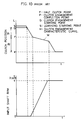
- This control is made according to the clutch engagement characteristics obtained from learning activities made under predetermined conditions. Such learning activities are shown in Fig. 10.
- a learning starting point S is stored in the memory of the main control unit 4.
- the clutch 6 is moved toward engagement from the learning starting point S to determine, as a learning point, a half clutch point F from the rpm v of the input shaft sensor 5a.
- an engagement starting point Q and an engagement completion point P are determined by taking predetermined offset distances 11 and 12 toward disengagement and engagement from the half clutch point F, thereby making a clutch engagement characteristic curve which includes the half clutch point F, the clutch engagement completion point P, and the engagement starting point Q.
- the clutch engagement characteristic curve M is stored in the memory.
- the above engagement starting point Q is taken as a learning starting point S to perform a similar learning activity.
- the half clutch point is determined by learning in the above example, two points; the engagement completion point and the engagement starting point may be determined by learning as described in Japanese Patent Application Kokai No. 60-34525.
- a starter switch 18 is connected at one end to a battery and at the other end to a starter relay 19 which consists of a relay coil 19a and a relay contact 19b.
- the relay coil 19a is connected to the main control unit 4 via a starter drive line 19c which is turned on under predetermined conditions.
- the relay 19b is connected to a starter motor 20 for starting the engine 8.
- the juncture between the starter switch 18 and the starter relay 19 is connected to the main control unit 4 via a starter signal line 19d.
- An emergency switch 21 permits the starter to start unconditionally in the case of an emergency such as an engine failure on a railroad crossing.
- the main control unit 4 not only controls the clutch 6 and the transmission 1 based on various input signals but also turns on the starter drive line 19c (L level) to enable the starter switch 18 to operate when the transmission 1 is in the neutral position.
- Japanese Patent Applications Kokoku No. 57-85318 and Kokai No. 59-213936 disclose that if there is no output from the engine rpm sensor, with the starter switch turned on, it is determined that the sensor is faulty, and the necessary backup operation is performed.
- control unit can make an incorrect determination that the engine rpm sensor is faulty.
- an object of the invention to provide an automatic transmission with a sensor fault detector able to detect a fault of an engine rpm sensor under all conditions, especially those of the starting of the engine.
- the object of the invention is achieved by a method according to one of the independent claims 1 and 4. This method shall be applied in an aspect of the invention to a self learning method of control of clutch engagement.
- Fig. 1 shows an automatic transmission with a sensor fault detector according to an embodiment of the invention.
- a memory 41 consists of a ROM and a RAM for storing programs and data used by the CPU 40 of a main control unit 4.
- the outputs of the engine rpm sensor 9, the input shaft sensor 5a, and the vehicle speed sensor 5b are fed to the CPU 40 via waveform shapers 42a-42c.
- the starter drive and signal lines 19c and 19d are connected to the CPU 40 via a relay driver circuit 43 and a receiver circuit 44, respectively.
- a gear position detector 40a determines whether the gear is set in the neutral based on a select signal from the selector 15 and whether the current gear position of the transmission 1 is neutral based on the current position signals from the respective potentiometers 2f and 2g via the transmission drive unit 2e.
- a starter switch detector 40b determines whether the starter drive line 19c is on when the starter switch 18 is turned on. Where there is no output from the engine rpm sensor 9 with the starter switch 18 turned on, a fault detector 40c determines that the engine rpm sensor 9 is fault if there is an output from the input shaft sensor 5a when the clutch 6 is connected temporarily by controlling the clutch control unit 70 which consists of the clutch drive unit 7b and the clutch actuator 7.
- Fig. 2 shows how a starter control routine is carried out.
- Step S21 it is determined whether the emergency switch 21 is on (Step S21). If it is on, control is transferred to Step S26, wherein the starter drive line 19c is turned on (L level) via the relay driver circuit 43, thereby enabling the starter switch 18 to operate. This makes it possible to get out quickly of a railway crossing, for example, in the case of an engine failure.
- Step S22 it is determined whether the selector 15 is in the neutral (Step S22). If it is in the neutral, it is determined whether the clutch 6 is disengaged (Step S23). If it is disengaged, control is transferred to Step S26 to turn on the starter drive line 19c.
- Step S24 If the clutch 6 is not disengaged in the step S23, the clutch 6 is disengaged (Step S24). Then, it is determined whether the transmission 1 is in the neutral (Step S25). If it is, the starter drive line 19c is turned on (Step S26). If it is not, control is transferred to Step S27 to set the transmission 1 in the neutral. If the selector 15 is not in the neutral in the step S22, control is transferred to Step S28 to turn off the starter drive line 19c.
- Step S31 it is determined whether the starter switch 18 is on. If it is, it is determined whether the starter drive line 19c is on in Step S32. If it is, it is determined whether there is any signal from the engine rpm sensor 9 in Step S33. If there is one, it is determined that there is no trouble, and the routine is terminated. If there is no signal in the Step S33, on the other hand, it is determined whether a predetermined period of time has passed since the starter switch 18 is turned on (Step S34). If it has, a fault flag is set in the RAM area of the memory 41 (Step S35).
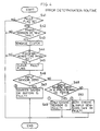
- Fig. 4 shows an error determination routine. First of all, it is determined whether the above fault flag is set (Step S41). If it is, it is determined whether the transmission 1 is in the neutral (Step S42). If it is, the clutch 6 is engaged temporarily (Step S43), and it is determined whether a predetermined period of time has passed (Step S44). If it has passed, the fault flag is cleared (Step S45), and it is determined whether there is an output from the input shaft sensor 5a (Step S46). If there is one, it is determined whether its value falls within a predetermined range (Step S48). If it does, it is determined that only the engine rpm sensor 9 is faulty (Step S49).
- Step S50 If it does not, it is determined that both of the engine rpm sensor 9 and the input shaft sensor 5a can be faulty (Step S50). If there is no output from the input shaft sensor 5a in the above step S46, it is determined that either the starter system or the battery is faulty. If a fault is detected, the driver is informed of the fault with an indicator such as a lamp, and the backup operation necessary for the fault is performed at a point (1), (2), or (3). By dividing faults into the above three faulty points or modes, it is assured that no inappropriate backup operation is performed.
- the fault detector 40c functions differently from that of the above embodiment. That is, the fault detector 40c in this embodiment controls the clutch control unit 70 to engage the clutch 6 when the starter is driven and, then, determines that the engine rpm sensor 9 is faulty if there is no output from the engine rpm sensor 9 but an output from the input shaft sensor 5a when the starter switch 18 is turned on.
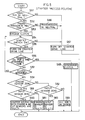
- Fig. 5 shows a starter process routine in this embodiment.
- the starter When the starter is turned on, it is determined whether the selector 15 is in the neutral (Step S51). If it is, it is determined whether the transmission 1 is indeed in the neutral (Step S52). If it is, the clutch control unit 70 is controlled so as to engage the clutch 6 (Step S53). Then, it is determined whether the starter switch 18 is on (Step S54). If it is, the starter drive line 19c is turned on so as to turn on the starter relay 19 (Step S55). Then, it is determined whether the on state of the starter relay 19 lasts for a predetermined period of time (Step S56). If it does not, it is determined whether the clutch 6 has been engaged (Step S57).
- Step S58 If it has not, control is transferred back to Step S54, while if it has, it is determined whether there is an output from the engine rpm sensor 9 (Step S58). If there is no output, it is determined whether there is an output from the input shaft sensor 5a in Step S59. If there is no output, it is determined that either the starter system (including the battery) or both of the engine rpm sensor 9 and the input shaft sensor 5a are faulty in Step S60. If there is an output from the input shaft sensor 5a in the above step S59, it is determined in Step 61 that only the engine rpm sensor 9 is faulty. If there is an output from the engine rpm sensor 9 in the above step S58, it is determined whether there is an output from the input shaft sensor 5a in Step S62.
- Step S63 If there is none, it is determined that the input shaft sensor 5a is faulty (Step S63). If there is one, it is determined that all are in good order (Step S64). If the predetermined period for fault determination passed since the starter relay is turned on in the above step S56, the clutch is disengaged in Step S65 to facilitate start of the engine. If the starter switch 18 is off in the above step S54, the transmission is shifted to the neutral in the above step S66, or the selector 15 is not in the neutral in the above step S61, the starter drive line 19c is turned off in Step S67.
- the clutch 6 is engaged after the output of the engine rpm sensor is checked so that the fault detection is delayed by that much.
- Fig. 6 shows an automatic transmission with a sensor fault detector according to still another embodiment of the invention, wherein like reference characters denote like or corresponding parts in Fig. 1.
- the CPU 40 includes a vehicle condition detector 40d, a clutch learning unit 40d, a learning determination unit 40e, and a fault determination unit 40g.
- the vehicle condition detector 40d detects the driving condition of the engine 8, the setting condition of the selector 15, and the conditions of the vehicle at rest or upon start based on various input signals.
- the clutch learning unit 40e determines the clutch position at which the output of the input shaft sensor 5a is no longer zero when the clutch 6 is moved toward engagement from the predetermined learning starting point via the clutch drive unit 7b when the vehicle is at rest with the selector 15 set in the neutral and control the clutch control unit 7b based on the learned clutch position. Also, it stores the clutch learning position in the memory 41 and sets or clears a flag F1 in the memory 41 depending whether the learning activity is completed. If the flag F1 is set, it means that the learning activity is completed while if the flag is cleared, it means that the learning activity is not completed. The learning determination unit 40f determines based on the flag F1 in the memory 41 whether the learning activity is in progress.
- the fault determination unit 40g determines that the engine rpm sensor 9 is faulty when there is no output from the engine rpm sensor 9 despite the presence of an output from the input shaft sensor 5a under a learning activity or upon start of the vehicle and sets or clears a flag F2 in the memory 41 depending whether the fault determination is completed in the learning activity. If the flag F2 is set, it means that the fault determination is not completed during the learning activity while if the flag is cleared, it means that the fault determination is completed. If the fault determination is not completed during the learning period, it is completed as the vehicle starts to move.
- Step L1 it is determined whether the selector 15 is in the neutral "N". If it is, it is determined whether the output of the vehicle speed sensor 5b is zero or the vehicle is at rest in Step L2. If it is, it is determined based on the flag F1 whether the learning activity is completed in Step L3. If it is not, the clutch 6 is engaged gradually so as to enter into a learning activity in Step L4. In Step L5, a flag F2 is set in anticipation that the fault determination is not completed during the learning period. In Step L6, it is determined whether the output of the input shaft sensor 5a is no longer zero.
- Step L7 If it is not, indicating that the clutch 6 is engaged, the flag F2 is cleared in Step L7 because it is possible to make a fault determination.
- the clutch position is stored in the memory 41 as a clutch learning position in Step L8.
- Step L9 a flag F1 is set to indicate that the learning activity is completed.
- Step L10 it is determined whether the output of the engine rpm sensor 9 is zero. If it is not, it is determined that there is no fault. If it is; namely, there is no output from the engine rpm sensor 9 despite the presence of an output from the input shaft sensor 5a, it is determined that the engine rpm sensor 9 is faulty in Step L11.
- the learning activity also detects a fault of the engine rpm sensor so that it is made even if the output of the engine rpm sensor is zero. If the selector 15 is not in the neutral in the above step L1, control is transferred to Step 12 to clear the flag F1 which indicates that the learning activity is completed and terminate the routine process. If the vehicle speed is not zero in the above step L2, the learning activity is completed in the step L3, the output of the input shaft sensor 5a is still zero in the step L6, or the output of the engine rpm sensor 9 is not zero in the step L10, the routine process is terminated and then started again from the step L1.
- the clutch 6 is engaged to start the vehicle in the same way as in the ordinary control. If the vehicle does not start, it is determined that the engine rpm sensor is faulty.
- Fig. 8 shows a fault detection at the time of start of the vehicle.
- Step S1 it is determined whether the engine rpm sensor is faulty. If it is, control is transferred to Step S3 to perform a starting operation wherein the clutch 6 is engaged up to a point corresponding to the amount of depression of the accelerator pedal. If no fault is detected, it is determined whether a flag F2 is set in Step S2. If it is, or the fault determination is not completed during the learning period, the starting operation is performed in the step S3 although the engine 8 is at rest. In Step S4, it is determined whether the flag F2 is set.
- Step S5 If it is not, or the fault determination is completed and control is jumped from the step S1 to the step S3 to complete the starting operation, the process is terminated because it is not necessary to do another fault determination. Since the fault determination is not completed when the flag F2 is set, it is determined whether the clutch 6 is engaged to a certain extent in Step S5. If it is, it is determined whether the output of the input shaft sensor 5a is zero in Step S6. If it is not, the fault determination is possible so that the flag F2 is cleared in Step S7. Then, it is determined whether the output of the engine rpm sensor 9 is zero in Step S8. If it is not, it is determined that there is no fault, and the process is terminated.
- Step S9 If it is, it is determined that the engine rpm sensor 9 is faulty in Step S9. If the flag F2 is not set in the above step S2, the fault determination is completed, and the engine rpm sensor 9 is not faulty so that it is determined whether the output of the engine rpm sensor 9 reaches a predetermined value x (300 rpm for example). If it does, control is transferred to the starting operation in the step S3, and the process is terminated via the step S4. If it does not, the clutch 6 is disengaged to prevent engine stop in Step S11, and the process is terminated. If the clutch 6 is not engaged in the step S5 or the output of the input shaft sensor 5a is zero in the step S6, the process is terminated.
- the fault determination is made when the clutch meet point is learned before start of the vehicle, it is very efficient. If the selector is shifted from the neutral to the drive with the fault determination uncompleted, the ordinary control is made to not only engage the clutch but also make fault determination, thereby assuring start of the vehicle and fault determination.
- the vehicle speed sensor 5b may be used to detect the rpm of an output of the clutch for making fault determination since the selector 15 is switched so that the transmission 1 is shifted from the neutral to the drive at the starting time.
- the clutch control unit when there is no output from the engine rpm sensor with the starter switch on, the clutch control unit is controlled so that the clutch is engaged temporarily. At this point, if there is an output from the clutch output rpm detector, it is determined that the engine rpm sensor is faulty so that it is possible to detect a fault of the engine rpm sensor accurately.
Landscapes
- Engineering & Computer Science (AREA)
- Mechanical Engineering (AREA)
- Chemical & Material Sciences (AREA)
- Combustion & Propulsion (AREA)
- Transportation (AREA)
- General Engineering & Computer Science (AREA)
- Physics & Mathematics (AREA)
- Fluid Mechanics (AREA)
- Automation & Control Theory (AREA)
- Hydraulic Clutches, Magnetic Clutches, Fluid Clutches, And Fluid Joints (AREA)
- Combined Controls Of Internal Combustion Engines (AREA)
- Control Of Transmission Device (AREA)
Description
- The present invention relates to a method for determining a sensor fault in an automatic transmission, comprising a starter switch, a clutch for transmitting an output of an engine, a transmission, a first detector for detecting an rpm of said engine, a second detector for detecting an output rpm of said clutch and a gear position detector for detecting a gear position of said transmission.
- A method according to the introductory part of the main claim is disclosed in the EP 0 241 216 A2. The method described there has as its object to provide a data whether specific sensors are faulty or not. To solve this object, the method described is carried out with fully engaged coupling and transmission engaged in a known ratio, in other words during driving. According to certain calculations, the sensor which is faulty can then be determined.
- It is, however, shown in the cited reference that the default of various kinds of speed indicators can be inspected only after the engine is started and the clutch connection is over. With this construction, it is not possible to identify a default of the engine.
- Further, this method known from the state of the art has not solved the problem to detect a fault of an engine rpm sensor when the electrical system is unstable at the time of start or when there is no output from the engine rpm sensor because of a breakdown of the starter driveline or the starter motor or a dead battery, that it disables the engine to start. A conventional unit is unable to detect such disabling causes which shall be detected according to the object of the present invention.
- Fig. 9 shows a conventional an automatic transmission including a clutch control unit. A well known parallel axis
gear type transmission 1 is controlled by atransmission actuator 2 composed of aselect actuator 2a and ashift actuator 2b. Theseactuators hydraulic drive unit 3 which consists of atank 3a, apump 3b, anaccumulator 3c, and a hydraulic pressure switching electromagnetic valve (not shown) to control the driving gear of thetransmission 1 via a pair ofpiston rods transmission drive unit 2e. Thedrive unit 2e is controlled through serial communications by a main control unit 4 which has a CPU, a read only memory (ROM), and a random access memory (RAM). A pair ofpotentiometers piston rods potentiometers drive unit 2e to control the gear position so that the position signals match the target signals from the main control unit 4. Aninput shaft sensor 5a senses the rpm v of an input shaft 1a of the transmission. Avehicle speed sensor 5b senses the vehicle speed or rpm V' of anoutput shaft 1b of thetransmission 1. The outputs of thesesensors - A
clutch 6 is interlocked with thepiston rod 7a of aclutch actuator 7 for control. The hydraulic pressure is supplied to theclutch actuator 7 from thedrive unit 3, and theclutch 6 is feedback controlled by the CPU of aclutch drive unit 7b so that the position of thepiston rod 7a which is sensed by apotentiometer 7c matches the target signal from the main control unit 4. Theclutch actuator 7 and theclutch drive unit 7b constitute aclutch control unit 70. Theclutch drive unit 7b is controlled by the main control unit 4 through serial communications. - An
engine 8 has acontrol unit 8a which is controlled by the main control unit 4. Anengine rpm sensor 9 senses the rpm V of anoutput shaft 8b of theengine 8. The revolutions of theengine 8 are transmitted to anaxle 10 via theclutch 6 and thetransmission 1. The output of theengine rpm sensor 9 is fed to the main control unit 4 for performing various controls such as a fuel supply control. More signals are fed to the main control unit 4 from anaccelerator pedal sensor 11, abrake pedal sensor 12, anexhaust brake switch 14, and aselector 15 to control thetransmission drive unit 2e, theclutch drive unit 7b, theengine control unit 8a, adisplay panel unit 16, and acontrol unit 17a for controlling a gearposition display panel 17. Consequently, the main control unit 4 controls theclutch 6 and thetransmission 1 according to the amount of depression of the accelerator pedal, the outputs of the respective sensors, and the positions of theselector 15 and gears of thetransmission 1. The gear position is controlled by theselect actuator 2a and theshift actuator 2b according to the set position of theselector 15. When theselector 15 is set in the position "1", "2", "3", or "R", the gear is controlled into the first, second, third, or reverse gear position. When theselector 15 is set in the automatic transmission position "D4" or "D5", the gear is controlled automatically from the first to the fourth gear position or from the second to the fifth gear position according to the gear transmission map based on the amount of depression of the accelerator pedal and the vehicle speed. - Upon the above transmission control, the
clutch 6 is automatically disengaged and then engaged by the main control unit 4 via theclutch actuator 7 and theclutch drive unit 7b. This control is made according to the clutch engagement characteristics obtained from learning activities made under predetermined conditions. Such learning activities are shown in Fig. 10. A learning starting point S is stored in the memory of the main control unit 4. When preconditions under which the engine is revolving, the gear is set in the neutral, and the vehicle is at rest, are satisfied, theclutch 6 is moved toward engagement from the learning starting point S to determine, as a learning point, a half clutch point F from the rpm v of theinput shaft sensor 5a. Then, an engagement starting point Q and an engagement completion point P are determined by takingpredetermined offset distances clutch 6 according to the clutch engagement characteristic curve thus obtained, it is possible to minimize the movement of theclutch 6, thereby not only speeding up the gear shift but also reducing the wear and tear of theclutch 6. - While only the half clutch point is determined by learning in the above example, two points; the engagement completion point and the engagement starting point may be determined by learning as described in Japanese Patent Application Kokai No. 60-34525.
- In Fig. 9, a
starter switch 18 is connected at one end to a battery and at the other end to astarter relay 19 which consists of arelay coil 19a and arelay contact 19b. Therelay coil 19a is connected to the main control unit 4 via astarter drive line 19c which is turned on under predetermined conditions. Therelay 19b is connected to astarter motor 20 for starting theengine 8. The juncture between thestarter switch 18 and thestarter relay 19 is connected to the main control unit 4 via astarter signal line 19d. Anemergency switch 21 permits the starter to start unconditionally in the case of an emergency such as an engine failure on a railroad crossing. - The main control unit 4 not only controls the
clutch 6 and thetransmission 1 based on various input signals but also turns on thestarter drive line 19c (L level) to enable thestarter switch 18 to operate when thetransmission 1 is in the neutral position. Japanese Patent Applications Kokoku No. 57-85318 and Kokai No. 59-213936 disclose that if there is no output from the engine rpm sensor, with the starter switch turned on, it is determined that the sensor is faulty, and the necessary backup operation is performed. - As has been described above, conventionally, when there is no output from the engine rpm sensor with the starter switch turned on, it is determined that the sensor is faulty. However, there can be other causes, such as a breakdown of the starter drive line or starter motor or a dead battery, that disable the engine to start. The conventional units are unable to detect such disabling causes.
- Also, because of electrically unstable conditions caused at the time of start of the starter motor, the control unit can make an incorrect determination that the engine rpm sensor is faulty.
- Accordingly, it is an object of the invention to provide an automatic transmission with a sensor fault detector able to detect a fault of an engine rpm sensor under all conditions, especially those of the starting of the engine. The object of the invention is achieved by a method according to one of the
independent claims 1 and 4. This method shall be applied in an aspect of the invention to a self learning method of control of clutch engagement. - The dependent claims are directed to advantageous embodiments of the invention.
- The above and other objects, features, and advantages of the invention will become more apparent from the following description when taken in conjunction with the accompanying drawings.
-
- Fig. 1 is a block diagram of a block diagram of an automatic transmission with a sensor fault detector according to an embodiment of the invention;
- Fig. 2 is a flowchart of a starter control routine for the automatic transmission of Fig. 1;
- Fig. 3 is a flowchart of a fault check routine for the automatic transmission of Fig. 1;
- Fig. 4 is a flowchart of a fault determination routine for the automatic transmission of Fig. 1;
- Fig. 5 is a starter process routine according to another embodiment of the invention;
- Fig. 6 is a block diagram of an automatic transmission with a sensor fault detector according to still another embodiment of the invention;
- Fig. 7 is a flowchart of a fault detection in a learning period for the automatic transmission of Fig. 6;
- Fig. 8 is a flowchart of a fault detection at the time of start for the automatic transmission of Fig. 6;
- Fig. 9 is a block diagram of a conventional automatic transmission; and
- Fig. 10 is a graph showing the clutch engaging characteristic curves.
- Fig. 1 shows an automatic transmission with a sensor fault detector according to an embodiment of the invention. Like reference characters designate like or corresponding parts in Fig. 9. A memory 41 consists of a ROM and a RAM for storing programs and data used by the
CPU 40 of a main control unit 4. The outputs of theengine rpm sensor 9, theinput shaft sensor 5a, and thevehicle speed sensor 5b are fed to theCPU 40 viawaveform shapers 42a-42c. The starter drive andsignal lines CPU 40 via arelay driver circuit 43 and areceiver circuit 44, respectively. Agear position detector 40a determines whether the gear is set in the neutral based on a select signal from theselector 15 and whether the current gear position of thetransmission 1 is neutral based on the current position signals from therespective potentiometers transmission drive unit 2e. A starter switch detector 40b determines whether thestarter drive line 19c is on when thestarter switch 18 is turned on. Where there is no output from theengine rpm sensor 9 with thestarter switch 18 turned on, afault detector 40c determines that theengine rpm sensor 9 is fault if there is an output from theinput shaft sensor 5a when theclutch 6 is connected temporarily by controlling theclutch control unit 70 which consists of theclutch drive unit 7b and theclutch actuator 7. - Fig. 2 shows how a starter control routine is carried out. First of all, it is determined whether the
emergency switch 21 is on (Step S21). If it is on, control is transferred to Step S26, wherein thestarter drive line 19c is turned on (L level) via therelay driver circuit 43, thereby enabling thestarter switch 18 to operate. This makes it possible to get out quickly of a railway crossing, for example, in the case of an engine failure. If theemergency switch 21 is not on, on the other hand, it is determined whether theselector 15 is in the neutral (Step S22). If it is in the neutral, it is determined whether theclutch 6 is disengaged (Step S23). If it is disengaged, control is transferred to Step S26 to turn on thestarter drive line 19c. If theclutch 6 is not disengaged in the step S23, theclutch 6 is disengaged (Step S24). Then, it is determined whether thetransmission 1 is in the neutral (Step S25). If it is, thestarter drive line 19c is turned on (Step S26). If it is not, control is transferred to Step S27 to set thetransmission 1 in the neutral. If theselector 15 is not in the neutral in the step S22, control is transferred to Step S28 to turn off thestarter drive line 19c. - Fig. 3 shows how an error check routine is carried out. In Step S31, it is determined whether the
starter switch 18 is on. If it is, it is determined whether thestarter drive line 19c is on in Step S32. If it is, it is determined whether there is any signal from theengine rpm sensor 9 in Step S33. If there is one, it is determined that there is no trouble, and the routine is terminated. If there is no signal in the Step S33, on the other hand, it is determined whether a predetermined period of time has passed since thestarter switch 18 is turned on (Step S34). If it has, a fault flag is set in the RAM area of the memory 41 (Step S35). - Fig. 4 shows an error determination routine. First of all, it is determined whether the above fault flag is set (Step S41). If it is, it is determined whether the
transmission 1 is in the neutral (Step S42). If it is, theclutch 6 is engaged temporarily (Step S43), and it is determined whether a predetermined period of time has passed (Step S44). If it has passed, the fault flag is cleared (Step S45), and it is determined whether there is an output from theinput shaft sensor 5a (Step S46). If there is one, it is determined whether its value falls within a predetermined range (Step S48). If it does, it is determined that only theengine rpm sensor 9 is faulty (Step S49). If it does not, it is determined that both of theengine rpm sensor 9 and theinput shaft sensor 5a can be faulty (Step S50). If there is no output from theinput shaft sensor 5a in the above step S46, it is determined that either the starter system or the battery is faulty. If a fault is detected, the driver is informed of the fault with an indicator such as a lamp, and the backup operation necessary for the fault is performed at a point (1), (2), or (3). By dividing faults into the above three faulty points or modes, it is assured that no inappropriate backup operation is performed. - According to another embodiment of the invention, the
fault detector 40c functions differently from that of the above embodiment. That is, thefault detector 40c in this embodiment controls theclutch control unit 70 to engage the clutch 6 when the starter is driven and, then, determines that theengine rpm sensor 9 is faulty if there is no output from theengine rpm sensor 9 but an output from theinput shaft sensor 5a when thestarter switch 18 is turned on. - Fig. 5 shows a starter process routine in this embodiment. When the starter is turned on, it is determined whether the
selector 15 is in the neutral (Step S51). If it is, it is determined whether thetransmission 1 is indeed in the neutral (Step S52). If it is, theclutch control unit 70 is controlled so as to engage the clutch 6 (Step S53). Then, it is determined whether thestarter switch 18 is on (Step S54). If it is, thestarter drive line 19c is turned on so as to turn on the starter relay 19 (Step S55). Then, it is determined whether the on state of thestarter relay 19 lasts for a predetermined period of time (Step S56). If it does not, it is determined whether theclutch 6 has been engaged (Step S57). If it has not, control is transferred back to Step S54, while if it has, it is determined whether there is an output from the engine rpm sensor 9 (Step S58). If there is no output, it is determined whether there is an output from theinput shaft sensor 5a in Step S59. If there is no output, it is determined that either the starter system (including the battery) or both of theengine rpm sensor 9 and theinput shaft sensor 5a are faulty in Step S60. If there is an output from theinput shaft sensor 5a in the above step S59, it is determined in Step 61 that only theengine rpm sensor 9 is faulty. If there is an output from theengine rpm sensor 9 in the above step S58, it is determined whether there is an output from theinput shaft sensor 5a in Step S62. If there is none, it is determined that theinput shaft sensor 5a is faulty (Step S63). If there is one, it is determined that all are in good order (Step S64). If the predetermined period for fault determination passed since the starter relay is turned on in the above step S56, the clutch is disengaged in Step S65 to facilitate start of the engine. If thestarter switch 18 is off in the above step S54, the transmission is shifted to the neutral in the above step S66, or theselector 15 is not in the neutral in the above step S61, thestarter drive line 19c is turned off in Step S67. - As has been described above, since the outputs of the
engine rpm sensor 9 and theinput shaft sensor 5b are checked with the clutch 6 engaged when the starter is driven, the time for fault determination is so short that it is possible to take the appropriate backup action quickly. In the first embodiment, the clutch is engaged after the output of the engine rpm sensor is checked so that the fault detection is delayed by that much. By contrast, in this embodiment, it is possible to detect a fault of theengine rpm sensor 9 in the same period as in the conventional model, thereby assuring safe, backup running. - Fig. 6 shows an automatic transmission with a sensor fault detector according to still another embodiment of the invention, wherein like reference characters denote like or corresponding parts in Fig. 1. The
CPU 40 includes avehicle condition detector 40d, aclutch learning unit 40d, alearning determination unit 40e, and afault determination unit 40g. Thevehicle condition detector 40d detects the driving condition of theengine 8, the setting condition of theselector 15, and the conditions of the vehicle at rest or upon start based on various input signals. Theclutch learning unit 40e determines the clutch position at which the output of theinput shaft sensor 5a is no longer zero when theclutch 6 is moved toward engagement from the predetermined learning starting point via theclutch drive unit 7b when the vehicle is at rest with theselector 15 set in the neutral and control theclutch control unit 7b based on the learned clutch position. Also, it stores the clutch learning position in the memory 41 and sets or clears a flag F1 in the memory 41 depending whether the learning activity is completed. If the flag F1 is set, it means that the learning activity is completed while if the flag is cleared, it means that the learning activity is not completed. The learningdetermination unit 40f determines based on the flag F1 in the memory 41 whether the learning activity is in progress. Thefault determination unit 40g determines that theengine rpm sensor 9 is faulty when there is no output from theengine rpm sensor 9 despite the presence of an output from theinput shaft sensor 5a under a learning activity or upon start of the vehicle and sets or clears a flag F2 in the memory 41 depending whether the fault determination is completed in the learning activity. If the flag F2 is set, it means that the fault determination is not completed during the learning activity while if the flag is cleared, it means that the fault determination is completed. If the fault determination is not completed during the learning period, it is completed as the vehicle starts to move. - Fig. 7 shows how the fault detection is made during the learning period. In Step L1, it is determined whether the
selector 15 is in the neutral "N". If it is, it is determined whether the output of thevehicle speed sensor 5b is zero or the vehicle is at rest in Step L2. If it is, it is determined based on the flag F1 whether the learning activity is completed in Step L3. If it is not, theclutch 6 is engaged gradually so as to enter into a learning activity in Step L4. In Step L5, a flag F2 is set in anticipation that the fault determination is not completed during the learning period. In Step L6, it is determined whether the output of theinput shaft sensor 5a is no longer zero. If it is not, indicating that theclutch 6 is engaged, the flag F2 is cleared in Step L7 because it is possible to make a fault determination. The clutch position is stored in the memory 41 as a clutch learning position in Step L8. In Step L9, a flag F1 is set to indicate that the learning activity is completed. In Step L10, it is determined whether the output of theengine rpm sensor 9 is zero. If it is not, it is determined that there is no fault. If it is; namely, there is no output from theengine rpm sensor 9 despite the presence of an output from theinput shaft sensor 5a, it is determined that theengine rpm sensor 9 is faulty in Step L11. - The learning activity also detects a fault of the engine rpm sensor so that it is made even if the output of the engine rpm sensor is zero. If the
selector 15 is not in the neutral in the above step L1, control is transferred to Step 12 to clear the flag F1 which indicates that the learning activity is completed and terminate the routine process. If the vehicle speed is not zero in the above step L2, the learning activity is completed in the step L3, the output of theinput shaft sensor 5a is still zero in the step L6, or the output of theengine rpm sensor 9 is not zero in the step L10, the routine process is terminated and then started again from the step L1. If theselector 15 is shifted to the drive "D" from the neutral "N" and the accelerator pedal is depressed under the condition that the fault check is not completed, theclutch 6 is engaged to start the vehicle in the same way as in the ordinary control. If the vehicle does not start, it is determined that the engine rpm sensor is faulty. - Fig. 8 shows a fault detection at the time of start of the vehicle. In Step S1, it is determined whether the engine rpm sensor is faulty. If it is, control is transferred to Step S3 to perform a starting operation wherein the
clutch 6 is engaged up to a point corresponding to the amount of depression of the accelerator pedal. If no fault is detected, it is determined whether a flag F2 is set in Step S2. If it is, or the fault determination is not completed during the learning period, the starting operation is performed in the step S3 although theengine 8 is at rest. In Step S4, it is determined whether the flag F2 is set. If it is not, or the fault determination is completed and control is jumped from the step S1 to the step S3 to complete the starting operation, the process is terminated because it is not necessary to do another fault determination. Since the fault determination is not completed when the flag F2 is set, it is determined whether theclutch 6 is engaged to a certain extent in Step S5. If it is, it is determined whether the output of theinput shaft sensor 5a is zero in Step S6. If it is not, the fault determination is possible so that the flag F2 is cleared in Step S7. Then, it is determined whether the output of theengine rpm sensor 9 is zero in Step S8. If it is not, it is determined that there is no fault, and the process is terminated. If it is, it is determined that theengine rpm sensor 9 is faulty in Step S9. If the flag F2 is not set in the above step S2, the fault determination is completed, and theengine rpm sensor 9 is not faulty so that it is determined whether the output of theengine rpm sensor 9 reaches a predetermined value x (300 rpm for example). If it does, control is transferred to the starting operation in the step S3, and the process is terminated via the step S4. If it does not, theclutch 6 is disengaged to prevent engine stop in Step S11, and the process is terminated. If theclutch 6 is not engaged in the step S5 or the output of theinput shaft sensor 5a is zero in the step S6, the process is terminated. - As has been described above, according to this embodiment, no fault determination is made in the period when the electric system is unstable (the starter motor is driven) so that it is possible to prevent incorrect fault determination. Since the fault determination is not made based on only the output of the
engine rpm sensor 9, it is possible to identify a fault of theengine rpm sensor 9 more accurately than before. - Since the fault determination is made when the clutch meet point is learned before start of the vehicle, it is very efficient. If the selector is shifted from the neutral to the drive with the fault determination uncompleted, the ordinary control is made to not only engage the clutch but also make fault determination, thereby assuring start of the vehicle and fault determination.
- While it is determined whether the output of the
input shaft sensor 5a is zero in the step S6 of Fig. 8, thevehicle speed sensor 5b may be used to detect the rpm of an output of the clutch for making fault determination since theselector 15 is switched so that thetransmission 1 is shifted from the neutral to the drive at the starting time. - While only one point or the half clutch point is determined by learning activities in the above embodiments, substantially the same results may be obtained by determining two points; the clutch engagement completion point and the clutch engagement starting point as described in Japanese Patent Application Kokai No. 60-34525. Furthermore, while the invention has been described by way of the clutch control unit of an automatic transmission, it is noted that its application is not limited to automatic transmissions.
- As has been described above, according to an aspect of the invention, when there is no output from the engine rpm sensor with the starter switch on, the clutch control unit is controlled so that the clutch is engaged temporarily. At this point, if there is an output from the clutch output rpm detector, it is determined that the engine rpm sensor is faulty so that it is possible to detect a fault of the engine rpm sensor accurately.
- In accordance with another aspect of the invention, if there is no output from the engine rpm sensor and there is an output from the clutch output rpm sensor when the clutch control unit is controlled to engage the clutch and the starter switch is turned on, it is determined that the engine rpm sensor is faulty so that it is possible to detect a fault of the engine rpm sensor accurately and quickly.
- In accordance with still another aspect of the invention, if there is an output from the clutch output rpm sensor but no output from the engine rpm sensor during the clutch learning activity or upon start of the vehicle, it is determined that the engine rpm sensor is faulty. Thus, no fault determination is made in the period when the starter motor is driven and the electric system is unstable so that it is possible to detect a fault of the engine rpm sensor more accurately than before.
Claims (8)
- Method for determining a sensor fault in an automatic transmission, comprising:- a starter switch (18),- a clutch (6) for transmitting an output of an engine,- a transmission (1),- a first detector (9) for detecting an rpm of said engine,- a second detector (5a) for detecting an output rpm of said clutch (6),- a gear position detector (2a, 2b) for detecting a gear position of said transmission (1),characterized in that the automatic transmission comprises- a clutch control unit (70) for controlling engagement of said clutch (6),- a control unit for controlling said clutch control unit (70) based on outputs of said respective detectors (9; 5a; 2a, 2b) and enabling said starter switch (18) to operate when said transmission (1) is in a neutral position, andsaid control unit includes a starter switch detector (40b) for determining whether said starter switch (18) is on and a fault determination unit (40c) for determining whether said first detector (9) is faulty,
said fault determination unit (40c) controls if said starter switch (18) is on and if there is no output from the engine rpm detector determines that the detector is faulty, and
said fault determination unit (40c) controls said clutch control unit (70) to engage said clutch (6) temporarily if there is no output from said first detector (9) with said starter switch (18) on and determines that said first detector (9) is faulty if there is an output from said second detector (5a). - Method for determining a sensor fault in an automatic transmission according to claim 1, characterized in that said first and second detectors (9, 5a) include an engine rpm sensor (9) which detects an output shaft rpm of said engine and an input shaft rpm of said transmission (1), respectively.
- Method for determining a sensor fault in an automatic transmission according to claim 2, characterized in that
said fault determination unit (40c) controls said clutch control unit (70) to engage said clutch (6) temporarily, if there is no output from said engine rpm sensor (9) with said starter switch (18) on and
determines whether there is an output from said input shaft sensor (5a), and, if there is one,
determines whether said output falls within a predetermined range, and, if it does,
determines that only said engine rpm sensor (9) is faulty, and, if it does not,
determines that both of said engine rpm sensor (9) and said input shaft sensor (5a) can be faulty, and, if there is no output from said input shaft sensor (5a),
determines that either a starter system or a battery is faulty. - Method for determining a sensor fault in an automatic transmission comprising:- a starter switch (18),- a clutch (6) for transmitting an output of an engine,- a transmission (1),- a first detector (9) for detecting an rpm of said engine,- a second detector (5a) for detecting an output rpm of said clutch (6),- a gear position detector (2a, 2b) for detecting a gear position of said transmission (1),characterized in that the automatic transmission comprises- a clutch control unit (70) for controlling engagement of said clutch (6),- a control unit for controlling said clutch control unit (70) based on outputs of said respective detectors (9; 5a; 2a, 2b) and enabling said starter switch (18) to operate when said transmission (1) is in a neutral position,said control unit includes a starter switch detector (40b) for determining whether said starter switch (18) is on and a fault determination unit (40c) for determining whether said first detector (9) is faulty,
said fault determination unit (40c) controls if said starter switch (18) is on and if there is no output from the engine rpm detector determines that the detector is faulty,
said fault determination unit (40c) controls said clutch control unit (70) to engage said clutch (6) in advance and determines that said first detector is faulty if there is no output from said first detector (9) but an output from said second detector (5a) with said starter switch (18) on. - Method for determining a sensor fault in an automatic transmission according to claim 4, characterized in that said first and second detectors (9, 5a) include an engine rpm sensor (9) which detects an output shaft rpm of said engine and an input shaft rpm of said transmission (1), respectively.
- Method for determining a sensor fault in an automatic transmission of claim 5, characterized in that said fault determination unit (40c) controls said clutch control unit (70) to engage said clutch (6) in advance and determines whether there is an output from said engine rpm sensor (9) with said starter switch (18) on and, if there is none,
determines whether there is an output from said input shaft sensor, and, if there is none,
determines that either a starter system including a battery or both of said engine rpm sensor (9) and said input shaft sensor (5a) are faulty, and, if there is an output from said input shaft sensor,
determines that only said engine rpm sensor (9) is faulty, and if there is an output from said engine rpm sensor (9),
determines whether there is an output from said input shaft sensor (5a), and if there is none,
determines that said input shaft sensor (5a) is faulty, and if there is one,
determines that all are in good order. - Method for determining a sensor fault in an automatic transmission according to one of the preceding claims characterized in that
said transmission further comprises a clutch control system with :- a clutch (6),- a first detector for detecting an rpm of an engine,- a second detector for detecting an output rpm of said clutch (6),- a clutch control unit for controlling engagement of said clutch (6),- a vehicle condition detector (40d) for detecting a condition of a vehicle,- a clutch learning unit (40e) for moving said clutch (6) toward engagement from a predetermined learning starting point by means of said clutch control unit (70) when said vehicle condition detector (40d) indicates that said vehicle is in a predetermined state, determines a clutch position where an output of said clutch (6) reaches a predetermined rpm, and controls said clutch control unit (70) based on said clutch position,- a learning determination unit (40f) for determining whether said clutch learning unit (40e) is in a learning activity and a fault determination unit (40c) for determining that said first detector is faulty if there is no output from said first detector but an output from a second detector when said clutch learning unit (40e) is in a learning activity or when a vehicle starts to move. - Method according to claim 7, characterized in that said fault determination unit is set to perform fault determination during a learning activity and, if said fault determination is not completed in a period of said learning activity, performs fault determination at a vehicle starting time.
Applications Claiming Priority (4)
| Application Number | Priority Date | Filing Date | Title |
|---|---|---|---|
| JP2026316A JP2690583B2 (en) | 1990-02-06 | 1990-02-06 | Automatic transmission |
| JP26316/90 | 1990-02-06 | ||
| JP28906/90 | 1990-02-08 | ||
| JP2028906A JP2690584B2 (en) | 1990-02-08 | 1990-02-08 | Clutch control device |
Publications (3)
| Publication Number | Publication Date |
|---|---|
| EP0441290A2 EP0441290A2 (en) | 1991-08-14 |
| EP0441290A3 EP0441290A3 (en) | 1992-02-19 |
| EP0441290B1 true EP0441290B1 (en) | 1995-08-02 |
Family
ID=26364081
Family Applications (1)
| Application Number | Title | Priority Date | Filing Date |
|---|---|---|---|
| EP91101451A Expired - Lifetime EP0441290B1 (en) | 1990-02-06 | 1991-02-04 | Automatic transmission with sensor fault detector |
Country Status (3)
| Country | Link |
|---|---|
| US (1) | US5064039A (en) |
| EP (1) | EP0441290B1 (en) |
| DE (1) | DE69111625T2 (en) |
Cited By (1)
| Publication number | Priority date | Publication date | Assignee | Title |
|---|---|---|---|---|
| DE19732924B4 (en) * | 1996-08-06 | 2010-11-11 | Luk Gs Verwaltungs Kg | Method for controlling an automated clutch |
Families Citing this family (20)
| Publication number | Priority date | Publication date | Assignee | Title |
|---|---|---|---|---|
| GB9312013D0 (en) * | 1993-06-10 | 1993-07-28 | Eaton Corp | Clutch disengage logic |
| GB2315836B (en) * | 1993-08-03 | 1998-04-01 | Luk Getriebe Systeme Gmbh | Motor vehicle |
| DE19719615B4 (en) * | 1996-05-14 | 2014-09-04 | Schaeffler Technologies Gmbh & Co. Kg | Device for the automated actuation of a torque transmission system |
| DE19729354B4 (en) * | 1996-07-12 | 2014-11-06 | Schaeffler Technologies Gmbh & Co. Kg | motor vehicle |
| GB2327108B (en) * | 1997-04-09 | 2002-04-10 | Luk Getriebe Systeme Gmbh | Motor vehicle with automatic clutch |
| DE19815260B4 (en) * | 1997-04-26 | 2006-03-02 | Luk Gs Verwaltungs Kg | motor vehicle |
| CN1163368C (en) * | 1997-07-10 | 2004-08-25 | 卢克驱动系统有限公司 | Device for authorizing unrestricted operating mode of vehicle control device in event of failure of ignition signal |
| DE19743089A1 (en) * | 1997-09-30 | 1999-04-29 | Bosch Gmbh Robert | Device and method for generating an error signal in a motor vehicle |
| JP3598847B2 (en) * | 1998-10-28 | 2004-12-08 | いすゞ自動車株式会社 | Clutch connection / disconnection device |
| DE19920803C2 (en) * | 1999-05-06 | 2003-05-08 | Zf Sachs Ag | Arrangement for actuating a friction clutch |
| WO2001063136A1 (en) * | 2000-02-24 | 2001-08-30 | Siemens Aktiengesellschaft | Automatically actuated clutch of a motor vehicle and a method for controlling a clutch of a motor vehicle |
| FR2834034B1 (en) * | 2001-12-20 | 2005-04-22 | Renault | METHOD FOR CONTROLLING AUTOMATED REPORTING STAGE TRANSMISSION |
| US7727111B2 (en) * | 2002-12-03 | 2010-06-01 | Zf Meritor, Llc | Vehicle driveline control including open clutch indicator |
| WO2005047723A1 (en) * | 2003-11-12 | 2005-05-26 | Hitachi, Ltd. | Automobile, its controller and its driving power controller |
| US20050109141A1 (en) * | 2003-11-25 | 2005-05-26 | Devore James H. | Automated mechanical transmission system |
| EP1661749A1 (en) * | 2004-11-25 | 2006-05-31 | LuK Lamellen und Kupplungsbau Beteiligungs KG | Starter securing system for vehicle engine |
| JP2009238322A (en) * | 2008-03-27 | 2009-10-15 | Fujitsu Ltd | Sensor connection detection circuit, sensor connection detection method, and information storage device |
| DE102008027675A1 (en) * | 2008-06-03 | 2009-12-10 | Getrag Getriebe- Und Zahnradfabrik Hermann Hagenmeyer Gmbh & Cie Kg | System and method for operating a dual-clutch transmission in case of failure of a motor speed sensor or a bus connection between control modules |
| US8255133B2 (en) * | 2009-06-05 | 2012-08-28 | Toyota Motor Engineering & Manufacturing North America, Inc. | Shift timing indicator system for vehicular manual transmission |
| US8676515B2 (en) * | 2009-12-16 | 2014-03-18 | Allison Transmission, Inc. | System and method for detecting clutch-related faults in an automatic transmission |
Family Cites Families (11)
| Publication number | Priority date | Publication date | Assignee | Title |
|---|---|---|---|---|
| JPS57160730A (en) * | 1981-03-27 | 1982-10-04 | Aisin Seiki Co Ltd | Automatic clutch control |
| DE3341293A1 (en) * | 1983-11-15 | 1985-05-23 | Wabco Westinghouse Fahrzeugbremsen GmbH, 3000 Hannover | Monitoring circuit for a rotational speed sensor |
| JPS60176925U (en) * | 1984-05-07 | 1985-11-25 | 日産自動車株式会社 | automatic clutch control device |
| GB8418749D0 (en) * | 1984-07-23 | 1984-08-30 | Eaton Ltd | Semi-automatic transmission control |
| US4569255A (en) * | 1984-09-12 | 1986-02-11 | Eaton Corporation | Automatic transmission controls with off-highway mode |
| JPS62103232A (en) * | 1985-10-30 | 1987-05-13 | Diesel Kiki Co Ltd | Clutch controller |
| JPS62103236A (en) * | 1985-10-30 | 1987-05-13 | Diesel Kiki Co Ltd | Clutch controller |
| JPH0694902B2 (en) * | 1986-03-13 | 1994-11-24 | アイシン精機株式会社 | Automatic transmission control device |
| US4849899A (en) * | 1986-04-07 | 1989-07-18 | Eaton Corporation | Method for controlling AMT system including speed sensor signal fault detection and tolerance |
| US4779490A (en) * | 1987-09-28 | 1988-10-25 | Saturn Corporation | Output speed sensor diagnostic control for a motor vehicle transmission |
| JPH01115735A (en) * | 1987-10-30 | 1989-05-09 | Diesel Kiki Co Ltd | Vehicle driving control device |
-
1991
- 1991-02-01 US US07/649,412 patent/US5064039A/en not_active Expired - Fee Related
- 1991-02-04 DE DE69111625T patent/DE69111625T2/en not_active Expired - Fee Related
- 1991-02-04 EP EP91101451A patent/EP0441290B1/en not_active Expired - Lifetime
Cited By (1)
| Publication number | Priority date | Publication date | Assignee | Title |
|---|---|---|---|---|
| DE19732924B4 (en) * | 1996-08-06 | 2010-11-11 | Luk Gs Verwaltungs Kg | Method for controlling an automated clutch |
Also Published As
| Publication number | Publication date |
|---|---|
| US5064039A (en) | 1991-11-12 |
| EP0441290A3 (en) | 1992-02-19 |
| EP0441290A2 (en) | 1991-08-14 |
| DE69111625T2 (en) | 1996-01-18 |
| DE69111625D1 (en) | 1995-09-07 |
Similar Documents
| Publication | Publication Date | Title |
|---|---|---|
| EP0441290B1 (en) | Automatic transmission with sensor fault detector | |
| JP2646133B2 (en) | Correction method for clutch control data | |
| US4698762A (en) | Cruise control apparatus for vehicles | |
| AU675336B2 (en) | Method and apparatus for controlling shift force in an automated mechanical transmission | |
| US5216938A (en) | Control apparatus with fail-safe faculty | |
| EP0696341B1 (en) | Clutch control system | |
| US5167311A (en) | Transmission control system with gear shift failure detection | |
| US5894758A (en) | Assisted lever-shifted transmission | |
| EP0130812B1 (en) | Apparatus for controlling gear changing operation in automatic transmission | |
| EP0314409B1 (en) | Vehicle-running control system | |
| CA2051084C (en) | System for starting an internal combustion engine for powering vehicles | |
| JPH0794211B2 (en) | Clutch pressure control device | |
| EP0420154B1 (en) | Clutch control system | |
| US5065851A (en) | Clutch control unit | |
| US4718309A (en) | Automatic transmission system for vehicles | |
| JPH086799B2 (en) | Electronic control device and method for automobile transmission | |
| EP0464406B1 (en) | Method for controlling gear transmission for vehicle | |
| JPH02162125A (en) | Automatic change gear control device | |
| JP2001304390A (en) | Controller for synchromesh type automatic transmission | |
| JP2696595B2 (en) | Vehicle clutch control device | |
| US4984455A (en) | System for detecting speed of engine for vehicle | |
| JP2690584B2 (en) | Clutch control device | |
| JP2690583B2 (en) | Automatic transmission | |
| JPH03219164A (en) | Shift indicating device for automatic transmission | |
| JPS63312557A (en) | Automatic transmission |
Legal Events
| Date | Code | Title | Description |
|---|---|---|---|
| PUAI | Public reference made under article 153(3) epc to a published international application that has entered the european phase |
Free format text: ORIGINAL CODE: 0009012 |
|
| AK | Designated contracting states |
Kind code of ref document: A2 Designated state(s): DE GB SE |
|
| PUAL | Search report despatched |
Free format text: ORIGINAL CODE: 0009013 |
|
| AK | Designated contracting states |
Kind code of ref document: A3 Designated state(s): DE GB SE |
|
| 17P | Request for examination filed |
Effective date: 19920504 |
|
| 17Q | First examination report despatched |
Effective date: 19930722 |
|
| GRAA | (expected) grant |
Free format text: ORIGINAL CODE: 0009210 |
|
| AK | Designated contracting states |
Kind code of ref document: B1 Designated state(s): DE GB SE |
|
| REF | Corresponds to: |
Ref document number: 69111625 Country of ref document: DE Date of ref document: 19950907 |
|
| PLBE | No opposition filed within time limit |
Free format text: ORIGINAL CODE: 0009261 |
|
| STAA | Information on the status of an ep patent application or granted ep patent |
Free format text: STATUS: NO OPPOSITION FILED WITHIN TIME LIMIT |
|
| 26N | No opposition filed | ||
| PGFP | Annual fee paid to national office [announced via postgrant information from national office to epo] |
Ref country code: GB Payment date: 19970127 Year of fee payment: 7 |
|
| PGFP | Annual fee paid to national office [announced via postgrant information from national office to epo] |
Ref country code: DE Payment date: 19970207 Year of fee payment: 7 |
|
| PGFP | Annual fee paid to national office [announced via postgrant information from national office to epo] |
Ref country code: SE Payment date: 19970217 Year of fee payment: 7 |
|
| PG25 | Lapsed in a contracting state [announced via postgrant information from national office to epo] |
Ref country code: GB Free format text: LAPSE BECAUSE OF NON-PAYMENT OF DUE FEES Effective date: 19980204 |
|
| PG25 | Lapsed in a contracting state [announced via postgrant information from national office to epo] |
Ref country code: SE Free format text: LAPSE BECAUSE OF NON-PAYMENT OF DUE FEES Effective date: 19980205 |
|
| GBPC | Gb: european patent ceased through non-payment of renewal fee |
Effective date: 19980204 |
|
| EUG | Se: european patent has lapsed |
Ref document number: 91101451.2 |
|
| PG25 | Lapsed in a contracting state [announced via postgrant information from national office to epo] |
Ref country code: DE Free format text: LAPSE BECAUSE OF NON-PAYMENT OF DUE FEES Effective date: 19981103 |