EP0314409B1 - Vehicle-running control system - Google Patents
Vehicle-running control system Download PDFInfo
- Publication number
- EP0314409B1 EP0314409B1 EP88309960A EP88309960A EP0314409B1 EP 0314409 B1 EP0314409 B1 EP 0314409B1 EP 88309960 A EP88309960 A EP 88309960A EP 88309960 A EP88309960 A EP 88309960A EP 0314409 B1 EP0314409 B1 EP 0314409B1
- Authority
- EP
- European Patent Office
- Prior art keywords
- clutch
- engine
- transmission
- gear
- malfunction
- Prior art date
- Legal status (The legal status is an assumption and is not a legal conclusion. Google has not performed a legal analysis and makes no representation as to the accuracy of the status listed.)
- Expired - Lifetime
Links
Images


Classifications
-
- B—PERFORMING OPERATIONS; TRANSPORTING
- B60—VEHICLES IN GENERAL
- B60W—CONJOINT CONTROL OF VEHICLE SUB-UNITS OF DIFFERENT TYPE OR DIFFERENT FUNCTION; CONTROL SYSTEMS SPECIALLY ADAPTED FOR HYBRID VEHICLES; ROAD VEHICLE DRIVE CONTROL SYSTEMS FOR PURPOSES NOT RELATED TO THE CONTROL OF A PARTICULAR SUB-UNIT
- B60W10/00—Conjoint control of vehicle sub-units of different type or different function
- B60W10/02—Conjoint control of vehicle sub-units of different type or different function including control of driveline clutches
-
- B—PERFORMING OPERATIONS; TRANSPORTING
- B60—VEHICLES IN GENERAL
- B60W—CONJOINT CONTROL OF VEHICLE SUB-UNITS OF DIFFERENT TYPE OR DIFFERENT FUNCTION; CONTROL SYSTEMS SPECIALLY ADAPTED FOR HYBRID VEHICLES; ROAD VEHICLE DRIVE CONTROL SYSTEMS FOR PURPOSES NOT RELATED TO THE CONTROL OF A PARTICULAR SUB-UNIT
- B60W10/00—Conjoint control of vehicle sub-units of different type or different function
- B60W10/04—Conjoint control of vehicle sub-units of different type or different function including control of propulsion units
- B60W10/06—Conjoint control of vehicle sub-units of different type or different function including control of propulsion units including control of combustion engines
-
- B—PERFORMING OPERATIONS; TRANSPORTING
- B60—VEHICLES IN GENERAL
- B60W—CONJOINT CONTROL OF VEHICLE SUB-UNITS OF DIFFERENT TYPE OR DIFFERENT FUNCTION; CONTROL SYSTEMS SPECIALLY ADAPTED FOR HYBRID VEHICLES; ROAD VEHICLE DRIVE CONTROL SYSTEMS FOR PURPOSES NOT RELATED TO THE CONTROL OF A PARTICULAR SUB-UNIT
- B60W10/00—Conjoint control of vehicle sub-units of different type or different function
- B60W10/10—Conjoint control of vehicle sub-units of different type or different function including control of change-speed gearings
- B60W10/11—Stepped gearings
-
- B—PERFORMING OPERATIONS; TRANSPORTING
- B60—VEHICLES IN GENERAL
- B60W—CONJOINT CONTROL OF VEHICLE SUB-UNITS OF DIFFERENT TYPE OR DIFFERENT FUNCTION; CONTROL SYSTEMS SPECIALLY ADAPTED FOR HYBRID VEHICLES; ROAD VEHICLE DRIVE CONTROL SYSTEMS FOR PURPOSES NOT RELATED TO THE CONTROL OF A PARTICULAR SUB-UNIT
- B60W30/00—Purposes of road vehicle drive control systems not related to the control of a particular sub-unit, e.g. of systems using conjoint control of vehicle sub-units, or advanced driver assistance systems for ensuring comfort, stability and safety or drive control systems for propelling or retarding the vehicle
- B60W30/18—Propelling the vehicle
-
- B—PERFORMING OPERATIONS; TRANSPORTING
- B60—VEHICLES IN GENERAL
- B60W—CONJOINT CONTROL OF VEHICLE SUB-UNITS OF DIFFERENT TYPE OR DIFFERENT FUNCTION; CONTROL SYSTEMS SPECIALLY ADAPTED FOR HYBRID VEHICLES; ROAD VEHICLE DRIVE CONTROL SYSTEMS FOR PURPOSES NOT RELATED TO THE CONTROL OF A PARTICULAR SUB-UNIT
- B60W50/00—Details of control systems for road vehicle drive control not related to the control of a particular sub-unit, e.g. process diagnostic or vehicle driver interfaces
- B60W50/02—Ensuring safety in case of control system failures, e.g. by diagnosing, circumventing or fixing failures
- B60W50/0205—Diagnosing or detecting failures; Failure detection models
-
- F—MECHANICAL ENGINEERING; LIGHTING; HEATING; WEAPONS; BLASTING
- F16—ENGINEERING ELEMENTS AND UNITS; GENERAL MEASURES FOR PRODUCING AND MAINTAINING EFFECTIVE FUNCTIONING OF MACHINES OR INSTALLATIONS; THERMAL INSULATION IN GENERAL
- F16H—GEARING
- F16H61/00—Control functions within control units of change-speed- or reversing-gearings for conveying rotary motion ; Control of exclusively fluid gearing, friction gearing, gearings with endless flexible members or other particular types of gearing
- F16H61/12—Detecting malfunction or potential malfunction, e.g. fail safe; Circumventing or fixing failures
-
- B—PERFORMING OPERATIONS; TRANSPORTING
- B60—VEHICLES IN GENERAL
- B60W—CONJOINT CONTROL OF VEHICLE SUB-UNITS OF DIFFERENT TYPE OR DIFFERENT FUNCTION; CONTROL SYSTEMS SPECIALLY ADAPTED FOR HYBRID VEHICLES; ROAD VEHICLE DRIVE CONTROL SYSTEMS FOR PURPOSES NOT RELATED TO THE CONTROL OF A PARTICULAR SUB-UNIT
- B60W50/00—Details of control systems for road vehicle drive control not related to the control of a particular sub-unit, e.g. process diagnostic or vehicle driver interfaces
- B60W50/02—Ensuring safety in case of control system failures, e.g. by diagnosing, circumventing or fixing failures
- B60W50/0205—Diagnosing or detecting failures; Failure detection models
- B60W2050/021—Means for detecting failure or malfunction
-
- B—PERFORMING OPERATIONS; TRANSPORTING
- B60—VEHICLES IN GENERAL
- B60W—CONJOINT CONTROL OF VEHICLE SUB-UNITS OF DIFFERENT TYPE OR DIFFERENT FUNCTION; CONTROL SYSTEMS SPECIALLY ADAPTED FOR HYBRID VEHICLES; ROAD VEHICLE DRIVE CONTROL SYSTEMS FOR PURPOSES NOT RELATED TO THE CONTROL OF A PARTICULAR SUB-UNIT
- B60W2510/00—Input parameters relating to a particular sub-units
- B60W2510/10—Change speed gearings
- B60W2510/1005—Transmission ratio engaged
-
- F—MECHANICAL ENGINEERING; LIGHTING; HEATING; WEAPONS; BLASTING
- F16—ENGINEERING ELEMENTS AND UNITS; GENERAL MEASURES FOR PRODUCING AND MAINTAINING EFFECTIVE FUNCTIONING OF MACHINES OR INSTALLATIONS; THERMAL INSULATION IN GENERAL
- F16H—GEARING
- F16H61/00—Control functions within control units of change-speed- or reversing-gearings for conveying rotary motion ; Control of exclusively fluid gearing, friction gearing, gearings with endless flexible members or other particular types of gearing
- F16H61/12—Detecting malfunction or potential malfunction, e.g. fail safe; Circumventing or fixing failures
- F16H2061/1208—Detecting malfunction or potential malfunction, e.g. fail safe; Circumventing or fixing failures with diagnostic check cycles; Monitoring of failures
-
- F—MECHANICAL ENGINEERING; LIGHTING; HEATING; WEAPONS; BLASTING
- F16—ENGINEERING ELEMENTS AND UNITS; GENERAL MEASURES FOR PRODUCING AND MAINTAINING EFFECTIVE FUNCTIONING OF MACHINES OR INSTALLATIONS; THERMAL INSULATION IN GENERAL
- F16H—GEARING
- F16H61/00—Control functions within control units of change-speed- or reversing-gearings for conveying rotary motion ; Control of exclusively fluid gearing, friction gearing, gearings with endless flexible members or other particular types of gearing
- F16H61/12—Detecting malfunction or potential malfunction, e.g. fail safe; Circumventing or fixing failures
- F16H2061/1232—Bringing the control into a predefined state, e.g. giving priority to particular actuators or gear ratios
-
- F—MECHANICAL ENGINEERING; LIGHTING; HEATING; WEAPONS; BLASTING
- F16—ENGINEERING ELEMENTS AND UNITS; GENERAL MEASURES FOR PRODUCING AND MAINTAINING EFFECTIVE FUNCTIONING OF MACHINES OR INSTALLATIONS; THERMAL INSULATION IN GENERAL
- F16H—GEARING
- F16H61/00—Control functions within control units of change-speed- or reversing-gearings for conveying rotary motion ; Control of exclusively fluid gearing, friction gearing, gearings with endless flexible members or other particular types of gearing
- F16H61/12—Detecting malfunction or potential malfunction, e.g. fail safe; Circumventing or fixing failures
- F16H2061/1244—Keeping the current state
-
- F—MECHANICAL ENGINEERING; LIGHTING; HEATING; WEAPONS; BLASTING
- F16—ENGINEERING ELEMENTS AND UNITS; GENERAL MEASURES FOR PRODUCING AND MAINTAINING EFFECTIVE FUNCTIONING OF MACHINES OR INSTALLATIONS; THERMAL INSULATION IN GENERAL
- F16H—GEARING
- F16H61/00—Control functions within control units of change-speed- or reversing-gearings for conveying rotary motion ; Control of exclusively fluid gearing, friction gearing, gearings with endless flexible members or other particular types of gearing
- F16H61/12—Detecting malfunction or potential malfunction, e.g. fail safe; Circumventing or fixing failures
- F16H2061/1256—Detecting malfunction or potential malfunction, e.g. fail safe; Circumventing or fixing failures characterised by the parts or units where malfunctioning was assumed or detected
- F16H2061/126—Detecting malfunction or potential malfunction, e.g. fail safe; Circumventing or fixing failures characterised by the parts or units where malfunctioning was assumed or detected the failing part is the controller
-
- F—MECHANICAL ENGINEERING; LIGHTING; HEATING; WEAPONS; BLASTING
- F16—ENGINEERING ELEMENTS AND UNITS; GENERAL MEASURES FOR PRODUCING AND MAINTAINING EFFECTIVE FUNCTIONING OF MACHINES OR INSTALLATIONS; THERMAL INSULATION IN GENERAL
- F16H—GEARING
- F16H61/00—Control functions within control units of change-speed- or reversing-gearings for conveying rotary motion ; Control of exclusively fluid gearing, friction gearing, gearings with endless flexible members or other particular types of gearing
- F16H61/12—Detecting malfunction or potential malfunction, e.g. fail safe; Circumventing or fixing failures
- F16H2061/1256—Detecting malfunction or potential malfunction, e.g. fail safe; Circumventing or fixing failures characterised by the parts or units where malfunctioning was assumed or detected
- F16H2061/1284—Detecting malfunction or potential malfunction, e.g. fail safe; Circumventing or fixing failures characterised by the parts or units where malfunctioning was assumed or detected the failing part is a sensor
-
- F—MECHANICAL ENGINEERING; LIGHTING; HEATING; WEAPONS; BLASTING
- F16—ENGINEERING ELEMENTS AND UNITS; GENERAL MEASURES FOR PRODUCING AND MAINTAINING EFFECTIVE FUNCTIONING OF MACHINES OR INSTALLATIONS; THERMAL INSULATION IN GENERAL
- F16H—GEARING
- F16H59/00—Control inputs to control units of change-speed-, or reversing-gearings for conveying rotary motion
- F16H59/14—Inputs being a function of torque or torque demand
- F16H59/24—Inputs being a function of torque or torque demand dependent on the throttle opening
-
- Y—GENERAL TAGGING OF NEW TECHNOLOGICAL DEVELOPMENTS; GENERAL TAGGING OF CROSS-SECTIONAL TECHNOLOGIES SPANNING OVER SEVERAL SECTIONS OF THE IPC; TECHNICAL SUBJECTS COVERED BY FORMER USPC CROSS-REFERENCE ART COLLECTIONS [XRACs] AND DIGESTS
- Y10—TECHNICAL SUBJECTS COVERED BY FORMER USPC
- Y10S—TECHNICAL SUBJECTS COVERED BY FORMER USPC CROSS-REFERENCE ART COLLECTIONS [XRACs] AND DIGESTS
- Y10S477/00—Interrelated power delivery controls, including engine control
- Y10S477/906—Means detecting or ameliorating the effects of malfunction or potential malfunction
Description
- The present invention relates to a vehicle-running control system for electronically controlling an engine, a transmission and a clutch.
- A vehicle-running control system for electronically controlling an engine, a transmission and a clutch is known well. In the known system, Japanese Patent Application Laid-Open Nos. 61-1851 and 61-1852 disclose a technique in which when a malfunction occurs in an engine combustion control device, the malfunction is detected to stop or suspend combustion in the engine, thereby enhancing safety of the vehicle running.
- Inconvenience occurs, however, in case where the vehicle-running control system disclosed in the above patents is applied to a vehicle having installed thereon a power steering device and/or a power brake device which are known well. Specifically, rotation of the engine, for example, is transmitted to the power steering device to actuate a hydraulic pump thereof such that hydraulic pressure obtained by the hydraulic pump is utilized as a power source for steering the vehicle. On the other hand, the power brake device employs its power source such as, for example, negative pressure or vacuum at an intake manifold connected to the engine, or compressed air pressure generated by a compressor to which the engine rotation is transmitted. When the combustion in the engine is suspended urgently during running of the vehicle, rotation of an axle is not transmitted to the engine, if the gear position of the transmission is a neutral or the clutch is in a disengaged position. As a result, power used in the power steering device and/or the power brake device is reduced or weakened, resulting in a deterioration of maneuverability of the vehicle.
- It is an object of the invention to provide a vehicle-running control system capable of ensuring to operate vehicle maneuvering means employing power produced due to rotation of an engine, even if combustion in the engine is stopped or suspended.
- According to the invention, there is provided a system for controlling running of a vehicle which includes an engine, shaft means drivingly connected to the engine, wheel means mounted on the shaft means for rotation therewith, vehicle maneuvering means employing power produced due to rotation of the engine, a clutch interposed between the engine and the shaft means, the clutch being capable of occupying an engaged position and a disengaged position, and a transmission interposed between the clutch and the shaft means, the transmission being capable of selecting a plurality of gear positions including a neutral, the system comprising:
- a) an engine-combustion control device including malfunction detecting means for detecting a malfunction of the engine combustion control device, and engine-combustion stopping means for stopping combustion in the engine in response to a malfunction detecting signal from the malfunction detecting means;
- b) a clutch control device including normal clutch control means outputting a control signal representative of the engaged and disengaged positions of the clutch, and an actuator for actuating the clutch on the basis of a control signal from the normal clutch control means; and
- c) a transmission control device including normal transmission control means for determining a gear position of the transmission to output a control signal, and an actuator for changing the gear position of the transmission on the basis of the control signal from the normal transmission control means,
-
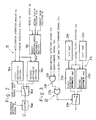
- Fig. 1 is a circuit block diagram showing an embodiment of a vehicle-running control system according to the invention;
- Fig. 2 is a circuit block diagram showing a detailed arrangement of a target rack position arithmetic unit illustrated in Fig. 1;
- Fig. 3 is a circuit block diagram showing a detailed arrangement of a clutch control unit illustrated in Fig. 1;
- Fig. 4 is a circuit block diagram showing a detailed arrangement of a target gear-position arithmetic unit illustrated in Fig. 1;
- Figs. 5 and 6 are flow charts of respective interrupt routines executed in another embodiment of the invention, which employs a microcomputer; and
- Fig. 7 is a flow chart showing a modification of the interrupt routine illustrated in Fig. 5.
- Embodiments of the invention will be described with reference to the accompanying drawings.
- Referring first to Figs. 1 through 4, in particular, to Fig. 1, there is shown a running control system installed on a vehicle. The vehicle comprises a
diesel engine 1, aclutch 2 and atransmission 3. Theclutch 2 is drivingly connected to anoutput shaft 1a of theengine 1, and thetransmission 3 is interposed between theclutch 2 and anaxle 4 on which a pair ofwheels 4a are mounted. Thetransmission 3 can select a plurality of gear positions including a neutral. Installed on the vehicle is vehicle maneuvering means including apower steering device 91 and apower brake device 92 which are known well. - The vehicle-running control system comprises an engine-combustion control device 10 for electronically controlling fuel supply to the
engine 1, aclutch control device 20 for electronically controlling theclutch 2, and atransmission control device 30 for electronically controlling thetransmission 3. - The vehicle-running control system further comprises a rotational-
speed detecting device 50 for detecting rotational speed of theengine 1. The rotational-speed detecting device 50 has apulser 51, anelectromagnetic pickup element 52 and a rotational-speedarithmetic unit 53. Thepulser 51 is fixedly mounted to theoutput shaft 1a of theengine 1 or to a camshaft (not shown) of afuel injection pump 12 interlocked with theoutput shaft 1a. Thefuel injection pump 12 will be described later. A plurality of cogs (not shown) are arranged on a peripheral surface of thepulser 51 in equidistantly spaced relation to each other. Theelectromagnetic pickup element 52 is arranged in the vicinity of the peripheral surface of thepulser 51 such that a pulse is outputted each time each cog passes by thepickup element 52. Pulses from theelectromagnetic pickup element 52 are inputted to the rotational-speedarithmetic unit 53. The rotational-speedarithmetic unit 53 measures a time interval between each pair of adjacent pulses from thepickup element 52. The rotational-speedarithmetic unit 53 calculates rotational speed Ne of theengine 1 on the basis of the measured data, to output a signal representative of the rotational speed Ne. - The vehicle-running control system further comprises an accelerator-operation-
amount detecting unit 60, a selector-position detecting unit 70, and a vehicle-speed detecting unit 80. The accelerator-operation-amount detecting unit 60 detects an operation amount Ac of an accelerator 6 to output a signal indicative of the operation amount Ac. The selector-position detecting unit 70 detects an operating position Se of a selector lever 7 for selecting a range of the gear position, to output a signal representative of the operating position Se. The vehicle-speed detecting unit 80 outputs a signal indicative of a vehicle speed Sp, and is constructed similarly to the aforesaid rotational-speed detecting device 50. A pulser (not shown) of the vehicle-speed detecting unit 80 is mounted to an output shaft of thetransmission 3. In this connection, it is to be understood that the vehicle-speed detecting unit 80 may calculate the vehicle speed Sp on the basis of the rotational speed Ne from the rotational-speed detecting unit 50 and the gear position of thetransmission 3. - The engine-combustion control device 10 has the aforesaid
fuel injection pump 12 which is connected, through apipe 11, to injection valves (not shown) associated respectively with a plurality of cylinders of theengine 1. Thefuel injection pump 12 has a control rack (not shown) for adjusting a fuel injection amount. Position of the control rack is electronically controlled by agovernor 13. Thegovernor 13 has an actuator (not shown) whosedrive circuit 14 is supplied with a control signal Gvc from agovernor control unit 15. Inputted to thegovernor control unit 15 are a signal indicative of a target rack position Lt from a target rack-positionarithmetic unit 16, and a signal indicative of an actual rack position Li from aposition sensor 17 for detecting the position of the control rack. Thegovernor control unit 15 executes PID calculation on the basis of a deviation between the target rack position Lt and the actual rack position Li, to output the governor control signal Gvc to thedrive circuit 14. The actuator of thegovernor 13 controls the control rack so as to bring the same into coincidence with the target rack position. - As shown in Fig. 2, the target rack-position
arithmetic unit 16 has a pair of first and secondarithmetic sections - The first
arithmetic section 16a calculates an optimum fuel injection amount on the basis of the accelerator operation amount Ac from the accelerator-operation-amount detecting unit 60 and the engine rotational speed Ne from the rotational-speed detecting unit 50. The firstarithmetic section 16a further calculates the target rack position corresponding to the optimum fuel injection amount. - The second
arithmetic section 16b executes PID calculation on the basis of a deviation between the engine rotational speed Ne from the rotational-speed detecting device 50 and target rotational speed Nref from a target rotational-speedarithmetic section 16c, to obtain the target rack position. The target rotational- speedarithmetic section 16c executes calculation on the basis of the vehicle speed Sp from the vehicle-speed detecting unit 80, and an actual clutch position CLp and a target gear position Gt to be described later, to output a signal representative of the target rotational speed Nref. - The signals outputted respectively from the first and second
arithmetic sections arithmetic section 16a. As a result, there is obtained an optimum fuel injection amount corresponding to the accelerator operation amount Ac and the engine rotational speed Ne. On the other hand, during the gear change, the switch 16d is switched in response to a gear change signal Gch to be described later, to select the signal representative of the target rack position Lt from the secondarithmetic section 16b. As a result, the engine rotational speed is so controlled as to enable the gear change and the operation bringing theclutch 2 to the engaged position, to be carried out smoothly, and is prevented from being abnormally raised instantaneously. - Another
switch 16e is connected to the output side of the signal selecting switch 16d, and is so designed as to be switched off in response to a malfunction detecting signal Em to be described later, to prevent the target rack-position signal Lt from being outputted. - Referring back to Fig. 1, the engine-combustion control device 10 further comprises a
malfunction detecting unit 19 for detecting a malfunction of the engine-combustion control device 10 to output the aforesaid malfunction detecting signal Em, and a pull-downlogic 18 serving as engine-combustion stopping means. - Specifically, the
malfunction detecting unit 19 detects a malfunction of therack position sensor 17. When the malfunction occurs in therack position sensor 17, the actual rack position Li from therack position sensor 17 is not brought into coincidence with the target rack position Lt from the target rack-positionarithmetic unit 16. Themalfunction detecting unit 19 compares the target rack-position signal Lt and the actual rack position signal Li with each other, to output the malfunction detecting signal Em when it is judged that a state, in which a deviation between both the signals Lt and Li exceeds a predetermined value, continues for a predetermined period of time. The malfunction detecting signal Em is sent to theswitch 16e (see Fig. 2) of the target rack-positionarithmetic unit 16 as described previously, to switch off theswitch 16e. Accordingly, outputting of the target rack-position signal Lt is interrupted. At the same time, the pull-downlogic 18 responds to the malfunction detecting signal Em to send a pull-down signal Pd to thegovernor control unit 15. Thegovernor control unit 15 receives the pull-down signal Pd to control the actuator of thegovernor 13 in such a manner as to pull the control rack to a position corresponding to zero of the fuel injection amount. As a result, the fuel injection amount from thefuel injection pump 12 to theengine 1 is brought to zero, to stop the combustion in theengine 1. - The
clutch control device 20 described above comprises, as shown in Fig. 1, anactuator 21, aclutch control unit 23 outputting a clutch control signal to a drive circuit 22 for theactuator 21, aclutch sensor 24, and a clutch-position detecting unit 25 for detecting a position of the clutch 2 on the basis of a signal from theclutch sensor 24 to output a signal representative of the actual clutch position CLp. - The
clutch control unit 23 has a pair of first and seconddeviation arithmetic units arithmetic unit 23a compares the actual clutch position CLp from the clutch-position detecting unit 25 with the target clutch position with respect to a time elapsing from an "ON" initiating point of time indicated on an "ON"map 23c, to output a control signal so as to eliminate a deviation between the target clutch position and the actual clutch position CLp. Thus, theclutch 2 is controlled in accordance with the "ON"map 23c, and is brought to the engaged position. Likewise, the second deviationarithmetic unit 23b outputs such a control signal as to bring the clutch 2 to the disengaged position in accordance with an "OFF"map 23d. - The control signals from the respective first and second
deviation arithmetic units switch 23e. The selecting operation of theswitch 23e is normally executed on the basis of a clutch "ON" and "OFF" command signal CLo from thetransmission control device 30 to be descried later. The signal CLo represents a clutch "ON" command when the signal CLo is at a high level, and represents a clutch "OFF" command when the signal CLo is at a low level. When the clutch "ON" and "OFF" command signal CLo is at the H-level, an output from the first deviationarithmetic unit 23a is sent to the drive circuit 22 to bring the clutch 2 to the engaged position. On the other hand, when the clutch "ON" and "OFF" command signal is at the L-level, an output from the second deviationarithmetic unit 23b is sent to the drive circuit 22 to bring the clutch 2 to the disengaged position. - The aforesaid components including the first deviation
arithmetic unit 23a, the second deviationarithmetic unit 23b, the "ON"map 23c, the "OFF"map 23d and theswitch 23e form normal clutch control means 23j. - The
clutch control unit 23 of theclutch control device 20 further has an urgent clutch switching means 23h composed of an ANDcircuit 23f and anOR circuit 23g. The malfunction detecting signal Em is inputted to one of a pair of input terminals of the ANDcircuit 23f. The gear-change signal Gch to be described later is inverted and is inputted to the other input terminal of the ANDcircuit 23f. An output from the ANDcircuit 23f is inputted to one of a pair of input terminals of theOR circuit 23g. The clutch "ON" and "OFF" command signal CLo is inputted to the other input terminal of theOR circuit 23g. - When a malfunction occurs at the engine combustion control device 10, the urgent clutch switching means 23h operates in the following manner. That is, the malfunction detecting signal Em from the
malfunction detecting unit 19 is sent to the ANDcircuit 23f. The output from the ANDcircuit 23f is brought to the high level during a period for which the ANDcircuit 23f receives the malfunction detecting signal Em, but does not receive the gear-change signal Gch representing the midst of gear change. If, at this time, theclutch 2 is in the disengaged position, theswitch 23e is switched to send the output from the first deviationarithmetic unit 23a to the drive circuit 22, thereby switching the clutch to the engaged position. On the other hand, when the ANDcircuit 23f receives the malfunction detecting signal Em, the output from the ANDcircuit 23f is not brought to the high level during the period for which the ANDcircuit 23f receives the gear-change signal Gch, so that theclutch 2 is maintained at its disengaged position. After a wait for completion of outputting of the gear-change signal Gch, the output from the ANDcircuit 23f is brought to the high level, to switch the clutch 2 to the engaged position. - The aforementioned
transmission control device 30 includes, as shown in Fig. 1, anactuator 31, a gear-change control unit 33 outputting a control signal to adrive circuit 32 for theactuator 31, a target gear-positionarithmetic unit 34 outputting a signal representative of a target gear-position Gt to the gear-change control unit 33, and agear position sensor 35 for detecting the gear position to output a signal representative of an actual gear-position Gp. The gear-change control unit 33 compares the actual gear position Gp with the target gear position Gt to output the control signal to thedrive circuit 32. In response to the control signal, theactuator 31 is operated to bring thetransmission 3 to the target gear position. At this gear change, the clutch "ON" and "OFF" command signal CLo for switching the clutch 2 between the engaged and disengaged positions and the gear change signal Gch indicative the midst of control of the gear change are outputted from the gear-change control unit 33 to theclutch control unit 23. - The target gear-position
arithmetic unit 34 has a firstarithmetic section 34a serving as normal transmission control means as shown in Fig. 4. Inputted to the firstarithmetic section 34a are signals respectively representative of the accelerator operation amount Ac, the vehicle speed Sp and the actual gear position Gp. Information in any one of a plurality ofmaps arithmetic section 34a. The firstarithmetic section 34a substitutes the accelerator operation amount Ac and the vehicle speed Sp into the selected map to obtain an optimum gear position, and to further obtain a final target gear position on the basis of comparison between the optimum gear position and the actual gear position Gp. - Normally, the signal representative of the target gear position Gt obtained in the manner described above is sent to the gear-
change control unit 33. - The target gear-position
arithmetic unit 34 further has urgent gear-position switching means 34h which includes a pair ofswitches neutral judging section 34m, a secondarithmetic section 34n, and a "malfunction" map 34p. The "malfunction" map 34p indicates the relationship between the vehicle speed Sp and the target gear position Gt. - The urgent gear position switching means 34h will be described in detail. The
neutral judging section 34m receives the actual gear-position signal Gp to judge whether or not the gear position is neutral. The secondarithmetic unit 34n calculates a target gear position at occurrence of a malfunction, on the basis of the vehicle speed signal Sp and the "malfunction" map 34p, during a period for which the secondarithmetic section 34n receives a neutral signal from theneutral judging section 34m. Theswitch 34i selects an output from theswitch 34k in place of an output from the firstarithmetic section 34a, when theswitch 34i receives the malfunction detecting signal Em. Theswitch 34k is in the illustrated position when theswitch 34k does not receive the neutral signal from theneutral judging section 34m, so that the actual gear position Gp becomes the target gear position Gt as it is. As a result, even after a malfunction occurs at the engine-combustion control device 10 so that theengine 1 is stopped in combustion, the gear position is maintained as it is at the malfunction detection. When theswitch 34k receives the neutral signal from theneutral judging section 34m, the output from the secondarithmetic section 34n is selected and serves as the target gear-position signal Gt. Accordingly, even if the gear position is neutral at detection of the malfunction, thetransmission 3 can be so controlled as to be brought to the optimum gear position in compliance with the vehicle speed. - The operation of the vehicle-running control system constructed as above will be described briefly. When a malfunction occurs at the engine-combustion control device 10, the
malfunction detecting unit 19 detects the malfunction, to output the malfunction detecting signal Em. The engine-combustion control device 10 responds to the malfunction detecting signal Em to suspend the fuel supply to theengine 1, thereby stopping combustion in theengine 1. As a result, it is possible to prevent reckless or uncontrolled running of theengine 1. In the vehicle-running control system according to the invention, at the stoppage of combustion in theengine 1, the gear position of thetransmission 3 is forcibly brought to one other than the neutral, and theclutch 2 is forcibly brought to the engaged position. This makes it possible to transmit rotation of theaxle 4 attendant upon running of the vehicle, to theengine 1. Thus, sufficient hydraulic pressure can be supplied as a power source to thepower steering device 91, and sufficient vacuum or compressed air pressure can be supplied as a power source to thepower brake device 92. As a result, maneuverability of thepower steering device 91 and thepower brake device 92 can be secured, making it possible to ensure stoppage of the vehicle and superior steering of the vehicle during a period until stoppage of the vehicle. - A microcomputer 200 (see Fig. 1) may be substituted for parts of the circuit illustrated in Fig. 1, which include, for example, the target rack position
arithmetic unit 16, the pull-downlogic 18 and themalfunction detecting unit 19 of the engine-combustion control device 10, theclutch control unit 23 of theclutch control device 20, and the gear-change control unit 33 and the target gear-positionarithmetic unit 34 of thetransmission control device 30. - The
microcomputer 200 executes interrupt routines which are started periodically, as shown respectively in Figs. 5 and 6. - The interrupt routine shown in Fig. 5 fulfills function substantially equal to the target rack-position
arithmetic unit 16 of the engine-combustion control device 10, the pull-downlogic 18 and themalfunction detecting unit 19. - It is first judged at a
step 100 whether or not a governor error flag is set. If the governor error flag is not set, the target rack position is calculated at astep 101, to output a signal representative of the calculated target rack position at astep 102. - Subsequently, it is judged at a
step 103 whether or not a deviation between the target rack position and the actual rack position is equal to or less than a minute predetermined value, that is, whether or not both the positions are substantially equal to each other. If both the positions are equal to each other, a timer is cleared at astep 104, and the program is completed. During normal running of the vehicle, thesteps 100 through 104 are repeatedly executed. - If the judgment at the
step 103 indicates that the actual rack position is different from the target rack position, [1] is added to the timer at astep 105. Subsequently, it is judged at astep 106 whether or not the timer exceeds a predetermined value. If the timer does not exceed the predetermined value, the program is completed. - At the
step 106, when the timer exceeds the predetermined value, that is, when a state in which the target rack position and the actual rack position are different from each other, continues for a predetermined period of time, it is judged that a malfunction occurs at therack position sensor 17 to set the governor error flag at astep 107. Subsequently, the governor pull-down control is executed to stop combustion in theengine 1 at astep 108. - In the above interrupt routine executed successively after detection of the malfunction, setting of the governor error flag is judged at the
step 100 to execute thestep 108 repeatedly, thereby maintaining the stoppage of combustion in theengine 1. - The interrupt routine of Fig. 6 executed by the
microcomputer 200 fulfills function substantially equal to theclutch control unit 23, the gear-change control unit 33, and the target gear-positionarithmetic unit 34. - It is first judged at a
step 110 whether or not a governor error flag is set. If the governor error flag is not set, the target gear position is calculated at astep 111 on the basis of the accelerator operation amount Ac, the vehicle speed Sp, and the actual gear position Gp, similarly to the firstarithmetic section 34a (see Fig. 4). Subsequently, it is judged at astep 112 whether or not the actual gear position coincides with the target gear position. If the judgment is negative, a signal for the gear change operation is outputted at astep 113, and the program is completed. At thestep 113, a command signal is also outputted for bringing the clutch 2 to the disengaged position during the gear change operation. If it is judged at thestep 112 that the actual gear position coincides with the target gear position, thestep 113 is passed, and the program is completed. During the normal running, thesteps 110 through 113 are executed repeatedly. - If it is judged at the
step 110 that the governor error flag is set, it is judged at astep 114 whether or not the target gear position stored in a register or a RAM is neutral. In case of the interrupt routine just after the malfunction detection, the target gear position judged at thestep 114 is one calculated at thestep 111 in the interrupt routine just before the malfunction detection. - If it is judged at the
step 114 that the target gear position is neutral, the target gear position is calculated at astep 115 on the basis of the vehicle speed Sp similarly to the secondarithmetic section 34n, to output a control signal for the gear change operation at astep 116. Thestep 116 includes outputting of a command signal for bringing the clutch 2 to the disengaged position just before the gear change operation. Finally, theclutch 2 is brought to the engaged position at astep 117, and the program is completed. - Since the target gear position is calculated at the
step 115 in the interrupt routine just after the malfunction detection, there is no such judgment at thestep 114 in the succeeding interrupt routine that the target gear position is neutral. - When it is judged at the
step 114 that the target gear position is not neutral, it is judged at astep 118 whether or not the actual gear position is equal to the target gear position. If the judgment is negative, thesteps step 118 is affirmative, thestep 116 is passed and thestep 117 is executed, so that the program is completed. - The target gear position just before the malfunction detection is substantially equal to the actual gear position at the malfunction detection. Accordingly, when the actual gear position is not neutral at the malfunction detection, the gear position is kept under the action of the
steps 114 through 118. On the other hand, when the actual gear position is neutral, the actual gear position is switched to a gear position in compliance with the vehicle speed and, subsequently, the gear position is kept. - Moreover, as shown in Fig. 7,
steps step 120 whether or not backup is possible. If possible, backup control is executed at thestep 121. If impossible, thestep 108 is executed similarly to the embodiment described previously. In this connection, the backup control does mean to control the control rack so as to keep the vehicle speed, for example, at the malfunction detection, in place of control of the control rack on the basis of the information on the accelerator operation amount and the engine rotational speed. - The invention is not limited to the above embodiments, but various modifications or variations can be made to the invention. For instance, the invention can equally be applied to a vehicle on which a gasoline engine is installed. In this case, combustion in the engine can be stopped by means of stoppage of ignition, fully closure of a throttle valve, or the like.
- The manner of detecting a malfunction at the engine combustion control device is not limited to one in the embodiment described previously. For example, when the rotational speed of the engine is raised abnormally and exceeds an allowance value, this may be detected as a malfunction.
wherein the transmission control device has urgent gear-position switching means which is operative in response to the malfunction detecting signal from the malfunction detecting means to output a control signal for bringing the gear position to one different from the neutral, to the actuator of the transmission control device.
Claims (3)
- A system for controlling running of a vehicle which includes an engine (1), shaft means drivingly connected to said engine, wheel means (4a) mounted on said shaft means for rotation therewith, vehicle maneuvering means (91, 92) employing power produced due to rotation of said engine, a clutch (2) interposed between said engine and said shaft means, said clutch being capable of occupying an engaged position and a disengaged position, and a transmission (3) interposed between said clutch and said shaft means, said transmission being capable of selecting a plurality of gear positions including a neutral, said system comprising:a) an engine-combustion control device (10) including malfunction detecting means (19) for detecting a malfunction of said engine combustion control device, and engine-combustion stopping means (18) for stopping combustion in said engine in response to a malfunction detecting signal (Em) from said malfunction detecting means;b) a clutch control device including normal clutch control means (20) outputting a control signal (CLp) representative of said engaged and disengaged positions of said clutch, and an actuator (21) for actuating said clutch on the basis of a control signal from said normal clutch control means; andc) a transmission control device (30) including normal transmission control means (33, 34) for determining a gear position of said transmission to output a control signal (Gt), and an actuator (31) for changing the gear position of said transmission on the basis of said control signal from said normal transmission control means,characterized in
that said clutch control means (20) has urgent clutch switching means (23h) which is operative in response to the malfunction detecting signal (Em) from said malfunction detecting means (19) to output a control signal for bringing said clutch (2) to said engaged position, to said actuator (21) of said clutch control device, and
that said transmission control device (30) has urgent gear-position switching means (34h) which is operative in response to the malfunction detecting signal (Em) from said malfunction detecting means (19) to output a control signal for bringing said gear position to one different from said neutral, to said actuator (31) of said transmission control device. - A system according to claim 1, characterized in that said urgent clutch switching means (23h) has means (23f) for prohibiting switching of said clutch to said engaged position during the midst of gear change, even when said urgent clutch switching means receives said malfunction detecting signal (Em).
- A system according to claim 1, characterized in that said urgent gear-position switching means (34h) includes arithmetic means (34n) for calculating a target gear position in accordance with vehicle speed, neutral judging means (34m) for judging whether or not said transmission (3) is neutral, and selecting means (34k), wherein when said neutral judging means judges that said transmission is neutral, said selecting means responds to the judgment by said neutral judging means to select the target gear position calculated by said arithmetic means, whereby the gear position of said transmission is so controlled as to be brought to said target gear position, and wherein when said neutral judging means judges that said transmission is not neutral, said selecting means selects the actual gear position at the malfunction detection as the target gear position, whereby the gear position of said transmission is maintained at the gear position at the malfunction detection.
Applications Claiming Priority (2)
| Application Number | Priority Date | Filing Date | Title |
|---|---|---|---|
| JP273455/87 | 1987-10-30 | ||
| JP62273455A JPH01115735A (en) | 1987-10-30 | 1987-10-30 | Vehicle driving control device |
Publications (3)
| Publication Number | Publication Date |
|---|---|
| EP0314409A2 EP0314409A2 (en) | 1989-05-03 |
| EP0314409A3 EP0314409A3 (en) | 1989-08-30 |
| EP0314409B1 true EP0314409B1 (en) | 1992-04-22 |
Family
ID=17528152
Family Applications (1)
| Application Number | Title | Priority Date | Filing Date |
|---|---|---|---|
| EP88309960A Expired - Lifetime EP0314409B1 (en) | 1987-10-30 | 1988-10-24 | Vehicle-running control system |
Country Status (5)
| Country | Link |
|---|---|
| US (1) | US4965730A (en) |
| EP (1) | EP0314409B1 (en) |
| JP (1) | JPH01115735A (en) |
| KR (1) | KR910005045B1 (en) |
| DE (1) | DE3870400D1 (en) |
Families Citing this family (19)
| Publication number | Priority date | Publication date | Assignee | Title |
|---|---|---|---|---|
| EP0482049B1 (en) * | 1989-07-14 | 1994-10-12 | ZF FRIEDRICHSHAFEN Aktiengesellschaft | Arrangement and process for operating a continuously variable driving unit of a motor vehicle |
| US5064039A (en) * | 1990-02-06 | 1991-11-12 | Zexel Corporation | Automatic transmission with sensor fault detector |
| AU653145B2 (en) * | 1990-03-29 | 1994-09-22 | Eaton Corporation | Throttle error detection logic |
| GB9007012D0 (en) * | 1990-03-29 | 1990-05-30 | Eaton Corp | Throttle error detection logic |
| JP2696595B2 (en) * | 1990-08-31 | 1998-01-14 | 株式会社ゼクセル | Vehicle clutch control device |
| US5219391A (en) * | 1991-12-06 | 1993-06-15 | Eaton Corporation | Transmission shifter having automatic adjustment of control parameters |
| US6026784A (en) | 1998-03-30 | 2000-02-22 | Detroit Diesel Corporation | Method and system for engine control to provide driver reward of increased allowable speed |
| JPH11108173A (en) | 1997-09-30 | 1999-04-20 | Mazda Motor Corp | Control device for automatic transmission |
| JP3391276B2 (en) * | 1998-09-24 | 2003-03-31 | トヨタ自動車株式会社 | Power plant control equipment |
| JP3691691B2 (en) * | 1999-08-06 | 2005-09-07 | ジヤトコ株式会社 | Automatic transmission failure detection device |
| DE10137597A1 (en) * | 2000-08-30 | 2002-03-14 | Luk Lamellen & Kupplungsbau | Method of diagnosing fault in motor vehicle clutch involves producing clutch actuator position signal for comparison to estimated signal |
| AU2003266191A1 (en) * | 2002-09-04 | 2004-04-30 | Luk Lamellen Und Kupplungsbau Beteiligungs Kg | Method and device for monitoring brake signals in a vehicle |
| US7727111B2 (en) * | 2002-12-03 | 2010-06-01 | Zf Meritor, Llc | Vehicle driveline control including open clutch indicator |
| DE102005012261A1 (en) * | 2005-03-17 | 2006-09-28 | Zf Friedrichshafen Ag | Method and device for controlling a motor vehicle drive train |
| JP5359508B2 (en) * | 2009-04-20 | 2013-12-04 | トヨタ自動車株式会社 | Shift control device |
| SE536237C2 (en) * | 2011-12-13 | 2013-07-16 | Scania Cv Ab | Apparatus and method for shifting a driveline of a motor vehicle |
| JP6212444B2 (en) * | 2014-07-16 | 2017-10-11 | 本田技研工業株式会社 | Control device for automatic transmission |
| JP6624974B2 (en) * | 2016-03-03 | 2019-12-25 | 株式会社クボタ | Multipurpose vehicle |
| CN108131364A (en) * | 2017-12-25 | 2018-06-08 | 徐州重型机械有限公司 | A kind of power drive system and its control method |
Family Cites Families (10)
| Publication number | Priority date | Publication date | Assignee | Title |
|---|---|---|---|---|
| US4539643A (en) * | 1981-10-01 | 1985-09-03 | Nissan Motor Company, Limited | Fuel cut-off control system in fuel injection internal combustion engine with automatic power transmission |
| JPS5932631A (en) * | 1982-08-17 | 1984-02-22 | Honda Motor Co Ltd | Fuel pump controlling apparatus for internal combustion engine |
| DE3301742A1 (en) * | 1983-01-20 | 1984-07-26 | Robert Bosch Gmbh, 7000 Stuttgart | SAFETY DEVICE FOR AN INTERNAL COMBUSTION ENGINE |
| DE3327157A1 (en) * | 1983-07-28 | 1985-02-07 | Robert Bosch Gmbh, 7000 Stuttgart | CONTROL DEVICE FOR STOPPING AN INTERNAL COMBUSTION ENGINE |
| JPS60135647A (en) * | 1983-12-22 | 1985-07-19 | Toyota Motor Corp | Fuel injection apparatus for diesel engine |
| JPH0615310B2 (en) * | 1983-12-30 | 1994-03-02 | いすゞ自動車株式会社 | Electronic emergency control system for vehicles |
| JPS611852A (en) * | 1984-06-12 | 1986-01-07 | Diesel Kiki Co Ltd | Fuel injection device |
| JPS611851A (en) * | 1984-06-12 | 1986-01-07 | Diesel Kiki Co Ltd | Fuel injection device |
| JPH0637145B2 (en) * | 1985-09-30 | 1994-05-18 | いすゞ自動車株式会社 | Vehicle emergency control device |
| JPS62103232A (en) * | 1985-10-30 | 1987-05-13 | Diesel Kiki Co Ltd | Clutch controller |
-
1987
- 1987-10-30 JP JP62273455A patent/JPH01115735A/en active Pending
-
1988
- 1988-10-04 KR KR1019880012914A patent/KR910005045B1/en not_active IP Right Cessation
- 1988-10-20 US US07/260,392 patent/US4965730A/en not_active Expired - Fee Related
- 1988-10-24 DE DE8888309960T patent/DE3870400D1/en not_active Expired - Lifetime
- 1988-10-24 EP EP88309960A patent/EP0314409B1/en not_active Expired - Lifetime
Also Published As
| Publication number | Publication date |
|---|---|
| DE3870400D1 (en) | 1992-05-27 |
| JPH01115735A (en) | 1989-05-09 |
| KR910005045B1 (en) | 1991-07-22 |
| EP0314409A2 (en) | 1989-05-03 |
| KR890006444A (en) | 1989-06-13 |
| US4965730A (en) | 1990-10-23 |
| EP0314409A3 (en) | 1989-08-30 |
Similar Documents
| Publication | Publication Date | Title |
|---|---|---|
| EP0314409B1 (en) | Vehicle-running control system | |
| US5638271A (en) | Apparatus and method for assisting gear engagement in controlling the automatic shifting of a manual-automatic transmission | |
| KR920000369B1 (en) | Control mechanism for automatic transmission | |
| US5216938A (en) | Control apparatus with fail-safe faculty | |
| EP0937917B1 (en) | Cruise control signal failure detecting system and method for automatic transmission | |
| US5393277A (en) | Variable electronically controlled shift points for a cruise control system | |
| US4732055A (en) | Shift control apparatus for automatic transmission system | |
| US5498195A (en) | Apparatus and method for verifying gear engagement in controlling the automatic shifting of a manual-automatic transmission | |
| US20060047395A1 (en) | Method and device for controlling gear shift of mechanical transmission | |
| US5591102A (en) | Apparatus and method for controlling a manual-automatic transmission after a power reset | |
| US5609548A (en) | Apparatus and method for commanding a gear after an aborted shift attempt in controlling a manual-automatic transmission | |
| JPH09507452A (en) | Clutch control system | |
| EP1487661B1 (en) | Driveline torque interrupt system | |
| US5005687A (en) | Control system for automatic transmission apparatus for vehicles | |
| EP0474107B1 (en) | Method and apparatus for controlling a clutch for vehicles | |
| US5588935A (en) | Throttle control for automated mechanical transmission | |
| US4984455A (en) | System for detecting speed of engine for vehicle | |
| US5170859A (en) | Constant-speed cruising system for a vehicle | |
| EP0635390B1 (en) | Method of controlling an automatic transmission of a commercial vehicle when accelerating from rest, and a control device operating according to said method | |
| JPS61232932A (en) | Method of controlling speed change in automatic transmission | |
| KR890002792B1 (en) | Automatic transmission apparatus for vehicle | |
| JPH0447477Y2 (en) | ||
| JPH0454350Y2 (en) | ||
| JPH05139190A (en) | Vehicle operation control device | |
| JPH0238129Y2 (en) |
Legal Events
| Date | Code | Title | Description |
|---|---|---|---|
| PUAI | Public reference made under article 153(3) epc to a published international application that has entered the european phase |
Free format text: ORIGINAL CODE: 0009012 |
|
| AK | Designated contracting states |
Kind code of ref document: A2 Designated state(s): DE GB |
|
| PUAL | Search report despatched |
Free format text: ORIGINAL CODE: 0009013 |
|
| AK | Designated contracting states |
Kind code of ref document: A3 Designated state(s): DE GB |
|
| 17P | Request for examination filed |
Effective date: 19900205 |
|
| 17Q | First examination report despatched |
Effective date: 19910709 |
|
| GRAA | (expected) grant |
Free format text: ORIGINAL CODE: 0009210 |
|
| AK | Designated contracting states |
Kind code of ref document: B1 Designated state(s): DE GB |
|
| REF | Corresponds to: |
Ref document number: 3870400 Country of ref document: DE Date of ref document: 19920527 |
|
| PLBE | No opposition filed within time limit |
Free format text: ORIGINAL CODE: 0009261 |
|
| STAA | Information on the status of an ep patent application or granted ep patent |
Free format text: STATUS: NO OPPOSITION FILED WITHIN TIME LIMIT |
|
| 26N | No opposition filed | ||
| PGFP | Annual fee paid to national office [announced via postgrant information from national office to epo] |
Ref country code: GB Payment date: 19971015 Year of fee payment: 10 |
|
| PGFP | Annual fee paid to national office [announced via postgrant information from national office to epo] |
Ref country code: DE Payment date: 19971031 Year of fee payment: 10 |
|
| PG25 | Lapsed in a contracting state [announced via postgrant information from national office to epo] |
Ref country code: GB Free format text: LAPSE BECAUSE OF NON-PAYMENT OF DUE FEES Effective date: 19981024 |
|
| GBPC | Gb: european patent ceased through non-payment of renewal fee |
Effective date: 19981024 |
|
| PG25 | Lapsed in a contracting state [announced via postgrant information from national office to epo] |
Ref country code: DE Free format text: LAPSE BECAUSE OF NON-PAYMENT OF DUE FEES Effective date: 19990901 |