EP0441188B1 - Dot-matrix printer - Google Patents
Dot-matrix printer Download PDFInfo
- Publication number
- EP0441188B1 EP0441188B1 EP91100890A EP91100890A EP0441188B1 EP 0441188 B1 EP0441188 B1 EP 0441188B1 EP 91100890 A EP91100890 A EP 91100890A EP 91100890 A EP91100890 A EP 91100890A EP 0441188 B1 EP0441188 B1 EP 0441188B1
- Authority
- EP
- European Patent Office
- Prior art keywords
- dot
- data
- elements
- print data
- Prior art date
- Legal status (The legal status is an assumption and is not a legal conclusion. Google has not performed a legal analysis and makes no representation as to the accuracy of the status listed.)
- Expired - Lifetime
Links
- 239000011159 matrix material Substances 0.000 title claims description 12
- 238000010438 heat treatment Methods 0.000 claims description 20
- 238000000034 method Methods 0.000 claims description 9
- 238000010586 diagram Methods 0.000 description 2
- 238000005516 engineering process Methods 0.000 description 2
- 230000006870 function Effects 0.000 description 1
- 108090000237 interleukin-24 Proteins 0.000 description 1
- 238000012986 modification Methods 0.000 description 1
- 230000004048 modification Effects 0.000 description 1
Images

Classifications
-
- B—PERFORMING OPERATIONS; TRANSPORTING
- B41—PRINTING; LINING MACHINES; TYPEWRITERS; STAMPS
- B41J—TYPEWRITERS; SELECTIVE PRINTING MECHANISMS, i.e. MECHANISMS PRINTING OTHERWISE THAN FROM A FORME; CORRECTION OF TYPOGRAPHICAL ERRORS
- B41J2/00—Typewriters or selective printing mechanisms characterised by the printing or marking process for which they are designed
- B41J2/485—Typewriters or selective printing mechanisms characterised by the printing or marking process for which they are designed characterised by the process of building-up characters or image elements applicable to two or more kinds of printing or marking processes
- B41J2/505—Typewriters or selective printing mechanisms characterised by the printing or marking process for which they are designed characterised by the process of building-up characters or image elements applicable to two or more kinds of printing or marking processes from an assembly of identical printing elements
- B41J2/515—Typewriters or selective printing mechanisms characterised by the printing or marking process for which they are designed characterised by the process of building-up characters or image elements applicable to two or more kinds of printing or marking processes from an assembly of identical printing elements line printer type
Definitions
- the invention relates to dot-matrix printers, and more particularly to a line head printer having dot-matrix pins or heating elements fixed across the width of a print sheet.
- dot-matrix printers There are two types of dot-matrix printers: a line head printer having a fixed print head and a moving head printer having a print head which shuttles across the print sheet and is provided with a plurality of dot-matrix pins or heating elements arranged in an order perpendicular to the width of a print sheet.
- the line head printer is provided with no head moving mechanism and has a simple mechanical structure.
- the moving head printer requires a head moving mechanism and has difficulty increasing its print speed due to mechanical limitations.
- the line head printer is faster.
- a line head printer has a plurality of rows, each consisting of dot elements, and moves a print sheet past the plurality of rows every time the dot elements in the plurality of rows have been energized. For example, suppose that a line head printer contains n rows equivalent to one print line where each row consists of a plurality of dot elements. Print data is input for every row until n rows of data (i.e. one print line) can be printed. Therefore, the line is printed without moving the print sheet. The line head printer then scrolls the print sheet forward a distance equivalent to one print line (i.e. n rows) after the n rows of data have been printed and repeats the process until all data has been printed.
- the process of printing data with a moving head printer is somewhat different.
- the end of the moving head has a plurality of dots, m, which is equivalent to a segment of a print line.
- Print data equivalent to the m dots is input to an end of the moving head and the dots in the moving head are energized thus printing this segment of the print line.
- the moving head then moves forward horizontally across the print sheet a distance equivalent to the segment of the print line.
- Data equivalent to the m dots is again input to the moving head and the above process is repeated until an end of the line is reached.
- the printer scrolls the print sheet forward to the next line and the entire process is repeated until all data has been printed.
- An object of this invention is to provide a printer having interchangeable line head and moving head technologies.
- the present invention comprises a line head printer that has a plurality of rows, each consisting of dot elements.
- the present invention further comprises a memory for arranging and storing line head printer print data in a specific pattern equivalent to one print line.
- a shift register reads the print data from the memory and forwards the print data to a series of latch registers.
- the latch registers are further connected to a plurality of gate registers and provide the print data to the gate registers.
- the gate registers are connected to a plurality of heating bodies which are further connected to corresponding dot elements in the line head printer.
- the gate registers When a series of strobe signals are received by the gate registers, the gate registers energize the heating elements to heat the appropriate dot elements in accordance with the print data stored in the latch registers. Therefore, as in the conventional line head printer, print data equivalent to an entire print line is printed. The line head printer then scrolls the print sheet forward a distance equivalent to one print line (i.e. n rows) after the print line has been printed and repeats the process until all data has been printed.
- the present invention can be arranged to read and print moving head printer data.
- the single shift register and the latch registers are eliminated, and the latch registers are replaced with shift registers.
- the memory arranges the data in a specific pattern equivalent to one print line and forwards this data directly to the shift registers in groups equivalent to segments of a print line as similar to the process in a conventional moving head printer.
- the gate circuits energize the heating elements to heat the appropriate dot elements in accordance with the print data stored in the shift registers.
- the printer scrolls the print sheet forward to the next line and the process is repeated until all of the data has been printed.
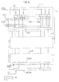
- FIG. 1 shows an embodiment of the invention.
- a fixed thermal print head 30 has 24 rows, each row having 832 dots extending in the width direction of a print sheet (hereinafter referred to as "dot row").
- This printer is also interchangeable with a type of moving head printer that forwards the print sheet in a line feed direction every 24 dots.
- Blocks L1 to L24 each form a single row of dots.
- Each block has heating bodies 32 for heating respective dot elements.
- a first end of each heating body 32 is commonly connected to a first terminal of a power supply 38.
- a second end of each heating body 32 is connected to a second end of the power supply 38 through gate circuits G1 to G16 respectively, each gate circuit grouping 52 dots.
- Blocks L1 to L24 include respective latch registers LR1 to LR24, each latch register accommodating 832 bits.
- the output of a preceding latch register is connected to the input of a succeeding latch register, and the latch signal inputs of each latch register are connected to the latch signal output of a shift register 34.
- the plurality of latch registers LR1 to LR24 is also connected in series with the shift register 34.
- a memory 36 reads data for every single dot row and develops the data of a single print line into a pattern of 24 x 832 dots and stores this developed print data. Memory 36 also inputs the print data to the shift register 34 which not only reads serial print data but also shifts the read data in accordance with a clock pulse CL.
- FIG. 2 is a timing chart showing the operation of the fixed thermal print head 30 as shown in Figure 1.
- a clock pulse CL signals the shift register 34 to read the print data from the memory 36 and to shift the read data.
- an 832nd clock pulse is generated, the print data equivalent to a single dot row is written to the shift register 34 in the form of developed dot pattern.
- each block of the print head has completed its read operation.
- a total of 16 strobe signals ST ( Figure 2) are applied sequentially through strobe terminals ST1 to ST16 to gate circuits G1 to G16 of each of the blocks L1 to L24, respectively.
- Each gate circuit is turned on or off in accordance with the output of each bit of the respective latch register to which the gate circuit is connected, thus energizing the corresponding heating elements 32 to print the data.
- the above operation is repeated to print the data of additional print lines.
- Figure 3 shows another embodiment of the invention.
- This embodiment has the following arrangement: Shift registers SR1 to SR24, instead of latch registers LR1 to LR24 as in the previous embodiment ( Figure 1), are disposed in the blocks L1 to L24, respectively.
- Print data stored in the memory 36 is input to the blocks in 24 dot groups at every clock pulse CL.
- the dot groups are segments of an entire print line as in a conventional moving head printer.
- the input of the print data equivalent to a single print line is terminated with the 832nd clock pulse, therefore, the print data equivalent to a single print line is input to the print head much faster (i.e. 24 times faster) than in the first embodiment.
- Both embodiments signal each block to energize a group of 52 dot elements at a time and complete the printing of the single print line data with the 16th strobe signal.
- the arrangement for writing the print data to the memory 36 is optional.
- a memory capable of receiving print data equivalent to a single print line which is developed into 24 dots segments sequentially transmitted as in a moving head printer can be used.
- a memory capable of receiving print data equivalent to a single print line which is developed into each dot row and serially transmitted as in a line head printer can be implemented. Therefore, a suitable memory can be selected according to the printer application.
- the fixed print head consisting of a plurality of dot rows can print the data equivalent to a plurality of dot rows (i.e. one print line) at one time.
- the structure of the print head is not only mechanically simple but also is free from mechanical speed restrictions.
- the print head according to the present invention can accommodate input of the moving head printer print data as well.
Description
- The invention relates to dot-matrix printers, and more particularly to a line head printer having dot-matrix pins or heating elements fixed across the width of a print sheet.
- There are two types of dot-matrix printers: a line head printer having a fixed print head and a moving head printer having a print head which shuttles across the print sheet and is provided with a plurality of dot-matrix pins or heating elements arranged in an order perpendicular to the width of a print sheet.
- The line head printer is provided with no head moving mechanism and has a simple mechanical structure. However, the moving head printer requires a head moving mechanism and has difficulty increasing its print speed due to mechanical limitations. Thus, the line head printer is faster.
- A line head printer has a plurality of rows, each consisting of dot elements, and moves a print sheet past the plurality of rows every time the dot elements in the plurality of rows have been energized. For example, suppose that a line head printer contains n rows equivalent to one print line where each row consists of a plurality of dot elements. Print data is input for every row until n rows of data (i.e. one print line) can be printed. Therefore, the line is printed without moving the print sheet. The line head printer then scrolls the print sheet forward a distance equivalent to one print line (i.e. n rows) after the n rows of data have been printed and repeats the process until all data has been printed.
- The process of printing data with a moving head printer is somewhat different. The end of the moving head has a plurality of dots, m, which is equivalent to a segment of a print line. Print data equivalent to the m dots is input to an end of the moving head and the dots in the moving head are energized thus printing this segment of the print line. The moving head then moves forward horizontally across the print sheet a distance equivalent to the segment of the print line. Data equivalent to the m dots is again input to the moving head and the above process is repeated until an end of the line is reached. Then, the printer scrolls the print sheet forward to the next line and the entire process is repeated until all data has been printed.
- Many printers use a combination of both the line head and moving head printer technologies. Although interchangeability between the function of a line head printer and that of a moving head printer is desireable, to date, no such interchangeability has been available. Therefore, print data for a line head printer cannot be used by the moving head printer and vice-versa.
- An object of this invention is to provide a printer having interchangeable line head and moving head technologies.
- As in the conventional line head printer, the present invention comprises a line head printer that has a plurality of rows, each consisting of dot elements. The present invention further comprises a memory for arranging and storing line head printer print data in a specific pattern equivalent to one print line. A shift register reads the print data from the memory and forwards the print data to a series of latch registers. The latch registers are further connected to a plurality of gate registers and provide the print data to the gate registers. The gate registers are connected to a plurality of heating bodies which are further connected to corresponding dot elements in the line head printer. When a series of strobe signals are received by the gate registers, the gate registers energize the heating elements to heat the appropriate dot elements in accordance with the print data stored in the latch registers. Therefore, as in the conventional line head printer, print data equivalent to an entire print line is printed. The line head printer then scrolls the print sheet forward a distance equivalent to one print line (i.e. n rows) after the print line has been printed and repeats the process until all data has been printed.
- Unlike conventional line head printers, the present invention can be arranged to read and print moving head printer data. To attain this capability, the single shift register and the latch registers are eliminated, and the latch registers are replaced with shift registers. Upon receiving the moving head printer print data, the memory arranges the data in a specific pattern equivalent to one print line and forwards this data directly to the shift registers in groups equivalent to segments of a print line as similar to the process in a conventional moving head printer. When the data representing the entire print line has been received by the shift registers, the gate circuits energize the heating elements to heat the appropriate dot elements in accordance with the print data stored in the shift registers. When the line is printed, the printer scrolls the print sheet forward to the next line and the process is repeated until all of the data has been printed.
- Preferred embodiment(s) of the invention will be described in detail with reference to the drawings wherein like reference numerals denote like or corresponding parts throughout.
- Figure 1 is a block diagram showing an embodiment of the invention;
- Figure 2 is a timing chart illustrative of the operation of the embodiment shown in Figure 1; and
- Figure 3 is a block diagram of an alternative embodiment of the invention.
- Figure 1 shows an embodiment of the invention. A fixed
thermal print head 30 has 24 rows, each row having 832 dots extending in the width direction of a print sheet (hereinafter referred to as "dot row"). This printer is also interchangeable with a type of moving head printer that forwards the print sheet in a line feed direction every 24 dots. Blocks L1 to L24 each form a single row of dots. Each block hasheating bodies 32 for heating respective dot elements. A first end of eachheating body 32 is commonly connected to a first terminal of a power supply 38. A second end of eachheating body 32 is connected to a second end of the power supply 38 through gate circuits G1 to G16 respectively, each gate circuit grouping 52 dots. Blocks L1 to L24 include respective latch registers LR1 to LR24, each latch register accommodating 832 bits. The output of a preceding latch register is connected to the input of a succeeding latch register, and the latch signal inputs of each latch register are connected to the latch signal output of a shift register 34. The plurality of latch registers LR1 to LR24 is also connected in series with the shift register 34. - A
memory 36 reads data for every single dot row and develops the data of a single print line into a pattern of 24 x 832 dots and stores this developed print data.Memory 36 also inputs the print data to the shift register 34 which not only reads serial print data but also shifts the read data in accordance with a clock pulse CL. - Figure 2 is a timing chart showing the operation of the fixed
thermal print head 30 as shown in Figure 1. In Figure 2, a clock pulse CL signals the shift register 34 to read the print data from thememory 36 and to shift the read data. When an 832nd clock pulse is generated, the print data equivalent to a single dot row is written to the shift register 34 in the form of developed dot pattern. - When a latch signal L is input upon generation of the 832nd clock pulse, the print data is written from the shift register to the first latch register and the print data of each latch register is written to its succeeding latch register. When this operation of updating the content of a succeeding latch register with the contents of a preceding latch register is repeated 24 times, each block of the print head has completed its read operation. At this time, a total of 16 strobe signals ST (Figure 2) are applied sequentially through strobe terminals ST1 to ST16 to gate circuits G1 to G16 of each of the blocks L1 to L24, respectively. Each gate circuit is turned on or off in accordance with the output of each bit of the respective latch register to which the gate circuit is connected, thus energizing the
corresponding heating elements 32 to print the data. The printing of the data consisting of a pattern of 24 x 832 dots, equivalent to a single print line, is terminated upon application of the 16th strobe signal which triggers the printer to forward the print sheet by the single print line. The above operation is repeated to print the data of additional print lines. - Figure 3 shows another embodiment of the invention. This embodiment has the following arrangement: Shift registers SR1 to SR24, instead of latch registers LR1 to LR24 as in the previous embodiment (Figure 1), are disposed in the blocks L1 to L24, respectively. Print data stored in the
memory 36 is input to the blocks in 24 dot groups at every clock pulse CL. The dot groups are segments of an entire print line as in a conventional moving head printer. The input of the print data equivalent to a single print line is terminated with the 832nd clock pulse, therefore, the print data equivalent to a single print line is input to the print head much faster (i.e. 24 times faster) than in the first embodiment. - Both embodiments signal each block to energize a group of 52 dot elements at a time and complete the printing of the single print line data with the 16th strobe signal.
- Also, even though the print data is developed into a pattern of 24 x 832 dots in the above embodiments, the arrangement for writing the print data to the
memory 36 is optional. For example, a memory capable of receiving print data equivalent to a single print line which is developed into 24 dots segments sequentially transmitted as in a moving head printer can be used. On the other hand, a memory capable of receiving print data equivalent to a single print line which is developed into each dot row and serially transmitted as in a line head printer can be implemented. Therefore, a suitable memory can be selected according to the printer application. - According to the invention, the fixed print head consisting of a plurality of dot rows can print the data equivalent to a plurality of dot rows (i.e. one print line) at one time. Requiring no moving mechanism, the structure of the print head is not only mechanically simple but also is free from mechanical speed restrictions. Furthermore, by consisting of a plurality of dot rows, the print head according to the present invention can accommodate input of the moving head printer print data as well.
- While this invention has been described in connection with what is presently considered to be the most practical and preferred embodiment, it is to be understood that the invention is not limited to the disclosed embodiment, but, on the contrary, is intended to cover various modifications and equivalent arrangements included within the scope of the appended claims.
Claims (7)
- A dot-matrix printer comprising:
a fixed thermal print head comprising:
a plurality of rows constituting a print line, each row having a length equal to a width of a print sheet, each row having a plurality of dot elements;
heating elements each of which can heat one of said dot elements;
a plurality of gate circuits connected to said heating elements for controlling heating of associated dot elements; and
register means for providing print data to said gate circuits;
a memory for processing and storing said print data to be provided to said register means at predetermined time intervals; and
means for moving said print sheet a distance equal to a print line, movement occurring in relation to a time cycle, said time cycle including a duration of time during which said dot elements in said plurality of rows are energized. - A dot-matrix printer as in claim 1 wherein said register means comprises:
a plurality of latch registers connected in succession; and
a shift register coupled to one of said latch registers, said shift register writing data to a first latch register upon receipt of a clock pulse and each of said latch registers writing data to a succeeding latch register upon receipt of an additional clock pulse, said writing continuing until all said latch registers are full. - A dot-matrix printer as in claim 1 wherein said heating elements heat said dot elements in accordance with said data when a predetermined clock pulse occurs.
- A dot-matrix printer comprising:
a fixed thermal print head comprising:
a plurality of rows constituting a print line, each row having a length equal to a width of a print sheet, each row having a plurality of dot elements;
heating elements each of which can heat one of said dot elements;
a plurality of gate circuits connected to said heating elements for controlling heating of associated dot elements; and
a plurality of shift registers, said shift registers providing print data to said gate circuits;
a memory for processing and storing said print data to be provided to said plurality of shift registers at predetermined time intervals, transfer of data from said memory to said shift registers continuing until all said shift registers are full; and
means for moving said print sheet a distance equal to a print line, movement occurring in relation to a time cycle, said time cycle including a duration of time during which said dot elements in said plurality of rows are energized. - A dot-matrix printer as in claim 4 wherein said heating elements heat said dot elements in accordance with said data when a predetermined clock pulse occurs.
- A printing method using a dot-matrix printer comprising the steps of:
storing print data in a memory;
generating a series of clock pulses and writing a pre-determined amount of said print data from said memory into a shift register in accordance with said series of clock pulses;
writing said print data from said shift register to a first latch register of a plurality of latch registers and writing said print data from each latch register to a succeeding latch register in accordance with predetermined pulses within said series of clock pulses, said writing continuing until all said latch registers are full;
heating a plurality of dot elements in accordance with said print data upon generation of a predetermined clock pulse within said series of clock pulses; and
advancing a print sheet a distance equivalent to a print line comprising said plurality of dot elements. - A printing method using a dot-matrix printer comprising the steps of:
storing print data in a memory;
generating a series of clock pulses and writing a pre-determined amount of said print data from said memory into a series of shift registers in accordance with said series of clock pulses, said writing continuing until all said shift registers are full;
heating a plurality of dot elements in accordance with said print data upon generation of a predetermined clock pulse within said series of clock pulses; and
advancing a print sheet a distance equivalent to a print line comprising said plurality of dot elements.
Applications Claiming Priority (2)
| Application Number | Priority Date | Filing Date | Title |
|---|---|---|---|
| JP2017469A JPH03221474A (en) | 1990-01-26 | 1990-01-26 | Dot printer |
| JP17469/90 | 1990-01-26 |
Publications (3)
| Publication Number | Publication Date |
|---|---|
| EP0441188A2 EP0441188A2 (en) | 1991-08-14 |
| EP0441188A3 EP0441188A3 (en) | 1991-10-23 |
| EP0441188B1 true EP0441188B1 (en) | 1994-06-22 |
Family
ID=11944879
Family Applications (1)
| Application Number | Title | Priority Date | Filing Date |
|---|---|---|---|
| EP91100890A Expired - Lifetime EP0441188B1 (en) | 1990-01-26 | 1991-01-24 | Dot-matrix printer |
Country Status (4)
| Country | Link |
|---|---|
| US (1) | US5233365A (en) |
| EP (1) | EP0441188B1 (en) |
| JP (1) | JPH03221474A (en) |
| DE (1) | DE69102550T2 (en) |
Families Citing this family (4)
| Publication number | Priority date | Publication date | Assignee | Title |
|---|---|---|---|---|
| JP3101382B2 (en) * | 1991-12-26 | 2000-10-23 | キヤノン株式会社 | Recording device, host system and recording system |
| JP3305455B2 (en) * | 1993-10-01 | 2002-07-22 | キヤノン株式会社 | Image forming apparatus and image forming method |
| US5675370A (en) | 1993-11-22 | 1997-10-07 | Intermec Corporation | Printhead having multiple print lines, and method and apparatus for using same |
| CN110154557B (en) * | 2019-04-29 | 2021-07-06 | 湖南鼎一致远科技发展有限公司 | Printing control method of thermal transfer printer and thermal transfer printer |
Family Cites Families (9)
| Publication number | Priority date | Publication date | Assignee | Title |
|---|---|---|---|---|
| US3893558A (en) * | 1974-05-17 | 1975-07-08 | Extel Corp | Special symbol generator for high speed printer |
| US4069485A (en) * | 1976-11-22 | 1978-01-17 | International Business Machines Corporation | Bidirectional ink jet printer with moving record receiver |
| JPS58145469A (en) * | 1982-02-24 | 1983-08-30 | Sony Corp | Printer |
| JPS59182758A (en) * | 1983-04-01 | 1984-10-17 | Fuji Xerox Co Ltd | Drive circuit for thermal head |
| JPH0614665B2 (en) * | 1984-09-07 | 1994-02-23 | 神崎製紙株式会社 | Thermal printer |
| JPS6211651A (en) * | 1985-07-10 | 1987-01-20 | Tokyo Electric Co Ltd | Printing method in dot printer |
| US4786917A (en) * | 1987-06-03 | 1988-11-22 | Eastman Kodak Company | Signal processing for a thermal printer |
| JPH082081B2 (en) * | 1987-08-28 | 1996-01-10 | 日本電気株式会社 | Print control circuit |
| EP0349812A3 (en) * | 1988-07-07 | 1990-05-16 | Gould Electronique S.A. | Thermal printing head and controller |
-
1990
- 1990-01-26 JP JP2017469A patent/JPH03221474A/en active Pending
-
1991
- 1991-01-24 EP EP91100890A patent/EP0441188B1/en not_active Expired - Lifetime
- 1991-01-24 DE DE69102550T patent/DE69102550T2/en not_active Expired - Fee Related
- 1991-01-25 US US07/645,838 patent/US5233365A/en not_active Expired - Fee Related
Also Published As
| Publication number | Publication date |
|---|---|
| JPH03221474A (en) | 1991-09-30 |
| EP0441188A3 (en) | 1991-10-23 |
| DE69102550T2 (en) | 1994-12-15 |
| EP0441188A2 (en) | 1991-08-14 |
| US5233365A (en) | 1993-08-03 |
| DE69102550D1 (en) | 1994-07-28 |
Similar Documents
| Publication | Publication Date | Title |
|---|---|---|
| EP0774358B1 (en) | Thermal Printer | |
| US4059183A (en) | Dot matrix printer with slanted print head and modular skewing of dot pattern information | |
| US6008831A (en) | Apparatus for controlling driving of thermal printhead | |
| US5719615A (en) | Apparatus for driving heating elements of a thermal head | |
| EP0295953A2 (en) | Printing method of thermal printer | |
| GB2243808A (en) | Deriving draft quality dot patterns from letter quality dot patterns in matrix printers | |
| EP0441188B1 (en) | Dot-matrix printer | |
| US4248147A (en) | Control system for dot matrix line printer using one print element per character | |
| US4611217A (en) | Thermal transfer color gradation printing apparatus | |
| US4560988A (en) | Thermal head driving method | |
| JPS6133711B2 (en) | ||
| US3845710A (en) | Print control logic circuitry for on-the-fly printers | |
| EP0506016B1 (en) | Improved method and circuit for historical control of thermal printing | |
| US4713623A (en) | Control system for matrix print head | |
| KR100398032B1 (en) | small printer | |
| US4459462A (en) | Drive system for energizing elements of a fixed bar printer | |
| JP2932606B2 (en) | Printing device | |
| JP2772170B2 (en) | Thermal head drive circuit and printing device | |
| JP2570723B2 (en) | Thermal head control circuit | |
| JPH0664212A (en) | Thermal head driving apparatus | |
| JPS63265661A (en) | Thermal head controlling system | |
| JPH0834138A (en) | Printing head driving circuit and printing head | |
| JPH05220988A (en) | Dot printing method | |
| JPS63141766A (en) | Printing system | |
| JPH04201274A (en) | Drive circuit of gradation expressing printing head |
Legal Events
| Date | Code | Title | Description |
|---|---|---|---|
| PUAI | Public reference made under article 153(3) epc to a published international application that has entered the european phase |
Free format text: ORIGINAL CODE: 0009012 |
|
| AK | Designated contracting states |
Kind code of ref document: A2 Designated state(s): DE FR GB |
|
| PUAL | Search report despatched |
Free format text: ORIGINAL CODE: 0009013 |
|
| AK | Designated contracting states |
Kind code of ref document: A3 Designated state(s): DE FR GB |
|
| 17P | Request for examination filed |
Effective date: 19920124 |
|
| 17Q | First examination report despatched |
Effective date: 19930907 |
|
| RAP1 | Party data changed (applicant data changed or rights of an application transferred) |
Owner name: KANZAKI PAPER MFG. CO., LTD. |
|
| GRAA | (expected) grant |
Free format text: ORIGINAL CODE: 0009210 |
|
| AK | Designated contracting states |
Kind code of ref document: B1 Designated state(s): DE FR GB |
|
| REF | Corresponds to: |
Ref document number: 69102550 Country of ref document: DE Date of ref document: 19940728 |
|
| RAP2 | Party data changed (patent owner data changed or rights of a patent transferred) |
Owner name: NEW OJI PAPER CO., LTD. |
|
| ET | Fr: translation filed | ||
| PG25 | Lapsed in a contracting state [announced via postgrant information from national office to epo] |
Ref country code: GB Effective date: 19950124 |
|
| PLBE | No opposition filed within time limit |
Free format text: ORIGINAL CODE: 0009261 |
|
| STAA | Information on the status of an ep patent application or granted ep patent |
Free format text: STATUS: NO OPPOSITION FILED WITHIN TIME LIMIT |
|
| 26N | No opposition filed | ||
| GBPC | Gb: european patent ceased through non-payment of renewal fee |
Effective date: 19950124 |
|
| PG25 | Lapsed in a contracting state [announced via postgrant information from national office to epo] |
Ref country code: FR Effective date: 19950929 |
|
| PG25 | Lapsed in a contracting state [announced via postgrant information from national office to epo] |
Ref country code: DE Effective date: 19951003 |
|
| REG | Reference to a national code |
Ref country code: FR Ref legal event code: ST |