EP0441171B1 - Medical device with germ barrier - Google Patents
Medical device with germ barrier Download PDFInfo
- Publication number
- EP0441171B1 EP0441171B1 EP91100785A EP91100785A EP0441171B1 EP 0441171 B1 EP0441171 B1 EP 0441171B1 EP 91100785 A EP91100785 A EP 91100785A EP 91100785 A EP91100785 A EP 91100785A EP 0441171 B1 EP0441171 B1 EP 0441171B1
- Authority
- EP
- European Patent Office
- Prior art keywords
- pin
- socket
- appliance according
- plug
- nozzle
- Prior art date
- Legal status (The legal status is an assumption and is not a legal conclusion. Google has not performed a legal analysis and makes no representation as to the accuracy of the status listed.)
- Expired - Lifetime
Links
Images


Classifications
-
- A—HUMAN NECESSITIES
- A61—MEDICAL OR VETERINARY SCIENCE; HYGIENE
- A61M—DEVICES FOR INTRODUCING MEDIA INTO, OR ONTO, THE BODY; DEVICES FOR TRANSDUCING BODY MEDIA OR FOR TAKING MEDIA FROM THE BODY; DEVICES FOR PRODUCING OR ENDING SLEEP OR STUPOR
- A61M39/00—Tubes, tube connectors, tube couplings, valves, access sites or the like, specially adapted for medical use
- A61M39/20—Closure caps or plugs for connectors or open ends of tubes
-
- A—HUMAN NECESSITIES
- A61—MEDICAL OR VETERINARY SCIENCE; HYGIENE
- A61M—DEVICES FOR INTRODUCING MEDIA INTO, OR ONTO, THE BODY; DEVICES FOR TRANSDUCING BODY MEDIA OR FOR TAKING MEDIA FROM THE BODY; DEVICES FOR PRODUCING OR ENDING SLEEP OR STUPOR
- A61M39/00—Tubes, tube connectors, tube couplings, valves, access sites or the like, specially adapted for medical use
- A61M39/02—Access sites
-
- A—HUMAN NECESSITIES
- A61—MEDICAL OR VETERINARY SCIENCE; HYGIENE
- A61M—DEVICES FOR INTRODUCING MEDIA INTO, OR ONTO, THE BODY; DEVICES FOR TRANSDUCING BODY MEDIA OR FOR TAKING MEDIA FROM THE BODY; DEVICES FOR PRODUCING OR ENDING SLEEP OR STUPOR
- A61M39/00—Tubes, tube connectors, tube couplings, valves, access sites or the like, specially adapted for medical use
- A61M39/10—Tube connectors; Tube couplings
- A61M39/16—Tube connectors; Tube couplings having provision for disinfection or sterilisation
- A61M39/162—Tube connectors; Tube couplings having provision for disinfection or sterilisation with antiseptic agent incorporated within the connector
Definitions
- the invention relates to a medical device for supplying or removing liquids by means of injection, infusion or transfusion, which has a connection with a supply or removal connector and a closure element for the connector, the closure element having a germ-inhibiting or germ-killing property is provided, which protrudes into the closed nozzle, and the element is designed as a pin.
- medical devices of this type for example cannulas, catheters, drainages, are used in a wide variety of configurations. They enable multiple Supply or removal of liquids, which is why the connector is to be closed by means of the closure element after the respective supply or removal of liquid.
- the connections for injection, infusion or transfusion products which also include enteral nutritional products and urine products, represent a potential danger point of contamination / contamination with multiple use (see study Prof. Daschner / Freiburg "Bacterial problems with infusion therapy", published “Clinical Pharmacology and Experimental Medicine", VII Kollogium Bad Kreuznach 1980).
- a so-called residual drop remains in the nozzle, which is generally designed as a positive or negative nozzle, after the liquid has been added or removed, which can germinate until the liquid is added or removed again and thus in the case of a subsequent withdrawal, for example drawn up by means of an injection syringe, is fed directly to the patient directly or to the patient when liquid is fed into the device.
- the system is only suitable for supplying and not also for removing liquids, since the valve prevents this.
- the open system does not ensure a permanent germ-inhibiting property, since it cannot be ruled out that air containing germs can get into the nozzle through the porous sealing plug.
- a closure element for tightly closing a nozzle in a medical device is known.
- the closure element is designed as a pin, the free end area of which has a reduced diameter compared to the remaining area of the pin, so that a radial gap is formed in the end area between the pin and the connecting piece.
- the gap is provided there in order to obtain a larger opening gap in the open position of the closure element.
- the device should be designed as a closed system in the feed and removal area.
- the object is achieved in a medical device of the type mentioned in that a radial gap is provided between the socket and the pin in the case of a socket which is sealed by means of the closure element.
- the medical device according to the invention presents itself as a closed system when the nozzle is closed, so that permanent sterility or sterility is ensured.
- the pin comes into contact with the residual drop and, because of its germ-inhibiting or germ-killing property, acts as a germ barrier.
- any pen material that is biologically compatible is considered suitable.
- antimicrobial agents are preferred in Form of metals and metal compounds intended, especially those that have an oligodynamic metal effect that is known.
- Wallpatiußer Karl Heinz: Practice of Sterilization - Disinfection - Preservation - Germ Identification - Industrial Hygiene / 4th, revised. u. adult Ed. - Thieme, 1988, there numbers 6 and 7, in particular 7.26.
- the pin which has the germ-inhibiting or germ-killing property is advantageously made of ceramic, glass, metal or plastic with an oligodynamic metal effect coating, in particular a silver chloride coating.
- the carrier element for the coating is designed to be extremely porous, which results in a coating over a larger effective surface.
- the element having the germ-inhibiting or germ-killing property consists entirely of a metal having the oligodynamic metal effect, for example of silver.
- a special embodiment of the invention provides that the closure element is designed as a stopper, with a stopper protruding partially into the stopper when the nozzle is closed, preferably in the manner of a closure / sealing cone that receives the pin, which is advantageously inserted into an axial bore of the stopper approach is.
- the pin and the sealing plug it is also possible for the pin and the sealing plug to form a component.
- the pin When the nozzle is closed, the pin expediently penetrates it up to its end facing away from the stopper, a radial gap should remain between the pin and the nozzle.
- the pin displaces part of the residual drop into the radial gap, which can increase the oligodynamic effect, since the residual drop surrounds the entire accessible surface of the pin.
- the closure element can be screwed onto the socket, moreover the A conical nozzle opening and the stopper of the sealing plug should be designed correspondingly conical, the conicity of the nozzle opening and stopper should in particular correspond to that of the conical extension of an injection syringe.
- Figure 1 shows the medical device in the area of the connection essential to the invention.
- the device there essentially consists of a housing 1, a connection 2 with a liquid channel 3 and a supply or removal nozzle 4 opening into the connection 2, which can be sealed tightly by means of a sealing plug 5.
- the connecting piece 4 has an external thread 6 and the sealing plug 5 has an internal thread 7, which makes it possible to screw the sealing plug 5 onto the connecting piece 4.
- the opening enclosed by the connecting piece 4 is in its opening section assigned to the upper region (based on the illustration in the figures) 8 in the form of a truncated cone tapering downwards (female Luer lock approach), to which a cylindrical opening section 9 adjoins the liquid channel 3.
- a plug extension 10 of the sealing plug 5 is designed as a truncated cone (male Luer lock cone) which receives a pin 12 in an axial bore 11.
- the pin 12 extends as far as the inner wall area 13 of the liquid channel 3 facing the socket 4 and has a circular cross section, a radial gap 15 being formed between the pin area 14 protruding from the plug extension 10 and the associated inner wall of the socket 4.
- the pen is made of ceramic and has an oligodynamic silver chloride coating.
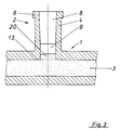
- FIG. 2 shows a partially illustrated syringe 16 with a conical extension 17, the conicity of which corresponds to that of the stopper extension 10 and which, according to the design of the sealing plug 5, is provided with an extension 18 with an internal thread, so that the syringe, as shown in this figure, also seals can be connected to the medical device. It is thus possible to withdraw liquid from the medical device into the syringe or to supply liquid from the syringe into the medical device.
- the syringe 16 is unscrewed from the connector 4, after the deconection, as shown in the illustration in FIG Spigot 4 displaces the pin 12 with its pin area 14, the residual drop 20, which escapes into the radial gap 15 and thus completely surrounds the pin area 14 and, due to the oligodynamic metal effect of its coating, the germ barrier becomes effective.
Abstract
Description
Die Erfindung betrifft ein medizinisches Gerät zur Zuführung bzw. Entnahme von Flüssigkeiten mittels Injektion, Infusion oder Transfusion, das einen Anschluß mit einem Zuführ- bzw. Entnahmestutzen sowie ein Verschlußelement für den Stutzen aufweist, wobei das Verschlußelement mit einem keimhemmende bzw. keimtötende Eigenschaft aufweisenden Element versehen ist, das bei verschlossenem Stutzen in diesen ragt, und das Element als Stift ausgebildet ist.The invention relates to a medical device for supplying or removing liquids by means of injection, infusion or transfusion, which has a connection with a supply or removal connector and a closure element for the connector, the closure element having a germ-inhibiting or germ-killing property is provided, which protrudes into the closed nozzle, and the element is designed as a pin.
Auf dem Gebiet der Medizintechnik finden derartige medizinische Geräte, beispielsweise Kanülen, Katheter, Drainagen, in vielfältigster Ausgestaltung Verwendung. Sie ermöglichen die mehrmalige Zuführung bzw. Entnahme von Flüssigkeiten, weshalb der Stutzen im Anschluß an die jeweilige Zuführung bzw. Entnahme von Flüssigkeit mittels des Verschlußelementes zu verschließen ist. Bekanntermaßen stellen die Anschlüsse bei Injektions-, Infusions- bzw. Transfusionsprodukten, wobei auch enterale Ernährungsprodukte und Urinprodukte einzubeziehen sind, eine potentielle Gefahrenstelle der Kontamination/Verkeimung bei Mehrfachbenutzung dar (siehe Studie Prof. Daschner/Freiburg "Bakterielle Probleme bei der Infusionstherapie", veröffentlicht "Klinische Pharmakologie und experimentelle Medizin", VII Kollogium Bad Kreuznach 1980).In the field of medical technology, medical devices of this type, for example cannulas, catheters, drainages, are used in a wide variety of configurations. They enable multiple Supply or removal of liquids, which is why the connector is to be closed by means of the closure element after the respective supply or removal of liquid. As is known, the connections for injection, infusion or transfusion products, which also include enteral nutritional products and urine products, represent a potential danger point of contamination / contamination with multiple use (see study Prof. Daschner / Freiburg "Bacterial problems with infusion therapy", published "Clinical Pharmacology and Experimental Medicine", VII Kollogium Bad Kreuznach 1980).
In der Praxis hat sich gezeigt, daß im Stutzen, der in aller Regel als positiver oder negativer Stutzen ausgebildet ist, nach erfolgter Zuführung bzw. Entnahme von Flüssigkeit ein sogenannter Resttropfen zurückbleibt, der bis zur erneuten Zuführung bzw. Entnahme von Flüssigkeit verkeimen kann und damit bei einer nachfolgenden Entnahme, beispielsweise mittels einer Injektionsspritze aufgezogen, dem Patienten mittelbar bzw. bei einer Zuführung von Flüssigkeit in das Gerät dem Patienten unmittelbar zugeführt wird.In practice it has been shown that a so-called residual drop remains in the nozzle, which is generally designed as a positive or negative nozzle, after the liquid has been added or removed, which can germinate until the liquid is added or removed again and thus in the case of a subsequent withdrawal, for example drawn up by means of an injection syringe, is fed directly to the patient directly or to the patient when liquid is fed into the device.
Aus der US-A-4,666,427 ist ein ausschließlich zum Zuführen von Flüssigkeiten geeignetes medizinisches Gerät der eingangs genannten Art bekannt. Dort entspricht der Außendurchmesser des Stiftes dem Innendurchmesser des Stutzens, so daß zwischen diesen kein Spalt verbleibt. Der Verschlußstopfen ist porös und insgesamt luftdurchlässig, so daß die wässrige Flüssigkeit durch diesen verdunsten kann, was beabsichtigt ist. Hierdurch werden Partikel, wie Bakterien an den Verschlußstopfen adhäriert und sterben nach Verdunstung des Wassers ab. Die Abtötung kann durch Zugabe einer antimikrobiellen Substanz zum porösen Verschlußstopfen oder durch Beschichtung des Verschlußstopfens damit unterstützt werden. Dieses offene System kann daher nur größere Flüssigkeitsverluste durch Verdunstung infolge des unterhalb der Zuspritzstelle angebrachten Ventiles vermeiden. Für alle Konnexionsstellen ohne diesen Schutz durch das Ventil ist das System ungeeignet, da unvorhersehbare Mengen an Flüssigkeit verdunsten können. Abgesehen hiervon ist das System auch nur zur Zuführung und nicht auch zur Entnahme von Flüssigkeiten geeignet, da das Ventil dieses verhindert. Schließlich gewährleistet das offene System keine dauernde keimhemmende Eigenschaft, da nicht ausgeschlossen werden kann, daß durch den porösen Verschlußstopfen Keime aufweisende Luft in den Stutzen gelangt.From US-A-4,666,427 a medical device of the type mentioned at the outset which is only suitable for supplying liquids is known. There, the outside diameter of the pin corresponds to the inside diameter of the socket, so that no gap remains between them. The plug is porous and air-permeable overall, so that the aqueous liquid can evaporate through it, which is intended. This causes particles such as bacteria to adhere to the sealing plugs and die after the water has evaporated. The killing can be supported by adding an antimicrobial substance to the porous sealing plug or by coating the sealing plug with it. This open system can therefore only avoid major liquid losses due to evaporation due to the valve located below the injection point. The system is unsuitable for all connection points without this protection by the valve, since unpredictable amounts of liquid can evaporate. Apart from this, the system is only suitable for supplying and not also for removing liquids, since the valve prevents this. Finally, the open system does not ensure a permanent germ-inhibiting property, since it cannot be ruled out that air containing germs can get into the nozzle through the porous sealing plug.
Aus der DE-C-35 15 665 ist ein Verschlußelement zum dichten Verschließen eines Stutzens bei einem medizinischens Gerät bekannt. Das Verschlußelement ist als Stift ausgebildet, dessen freier Endbereich einen gegenüber dem Restbereich des Stiftes reduzierten Durchmesser aufweist, sodaß im Endbereich ein Radialspalt zwischen dem Stift und dem Stutzen gebildet ist. Der Spalt ist dort vorgesehen, um einen größeren Öffnungsspalt in der Offen-Stellung des Verschlußelements zu erhalten.From DE-C-35 15 665 a closure element for tightly closing a nozzle in a medical device is known. The closure element is designed as a pin, the free end area of which has a reduced diameter compared to the remaining area of the pin, so that a radial gap is formed in the end area between the pin and the connecting piece. The gap is provided there in order to obtain a larger opening gap in the open position of the closure element.
Es ist Aufgabe vorliegender Erfindung, das medizinische Gerät der genannten Art so weiter zu bilden, daß die Sterilität der im Gerät befindlichen Flüssigkeit insgesamt sichergestellt ist, das heißt auch die des Resttropfens, wobei hierunter selbstverständlich auch mehrere Tropfen zu verstehen sind. Das Gerät soll im Zuführ- und Entnahmebereich als geschlossenes System ausgebildet sein.It is an object of the present invention to further develop the medical device of the type mentioned in such a way that the sterility of the liquid in the device is ensured overall, that is to say that of the residual drop, which of course also includes several drops. The device should be designed as a closed system in the feed and removal area.
Gelöst wird die Aufgabe bei einem medizinischen Gerät der genannten Art dadurch, daß ein Radialspalt zwischen dem Stutzen und dem Stift bei mittels dem Verschlußelement dicht verschlossenem Stutzen vorgesehen ist.The object is achieved in a medical device of the type mentioned in that a radial gap is provided between the socket and the pin in the case of a socket which is sealed by means of the closure element.
Das erfindungsgemäße medizinische Gerät stellt sich bei verschlossenem Stutzen als geschlossenes System dar, so daß eine dauernde Sterilität bzw. Keimfreiheit gewährleistet ist. Der Stift gelangt bei verschlossenem Stutzen in Kontakt mit dem Resttropfen und wirkt aufgrund dessen keimhemmender bzw. keimtötender Eigenschaft als Keimsperre. Grundsätzlich wird jedes Stiftmaterial als geeignet angesehen, das biologisch verträglich ist. Vorzugsweise ist jedoch an antimikrobielle Wirkstoffe in Form von Metallen und Metallverbindungen gedacht, insbesondere solche, die eine oligodynamische Metallwirkung aufweisen, die bekannt ist. Verwiesen wird in diesem Zusammenhang auf Wallhäußer, Karl Heinz: Praxis der Sterilisation - Desinfektion - Konservierung - Keimidentifizierung - Betriebshygiene / 4., überarb. u. erw. Aufl. - Thieme, 1988, dort die Ziffern 6. und 7., insbesondere 7.26..The medical device according to the invention presents itself as a closed system when the nozzle is closed, so that permanent sterility or sterility is ensured. When the nozzle is closed, the pin comes into contact with the residual drop and, because of its germ-inhibiting or germ-killing property, acts as a germ barrier. In principle, any pen material that is biologically compatible is considered suitable. However, antimicrobial agents are preferred in Form of metals and metal compounds intended, especially those that have an oligodynamic metal effect that is known. In this connection, reference is made to Wallhäußer, Karl Heinz: Practice of Sterilization - Disinfection - Preservation - Germ Identification - Industrial Hygiene / 4th, revised. u. adult Ed. - Thieme, 1988, there
Vorteilhaft besteht der die keimhemmende bzw. keimtötende Eigenschaft aufweisende Stift aus Keramik, Glas, Metall oder Kunststoff mit einer oligodynamischen Metallwirkung aufweisenden Beschichtung, insbesondere einer Silberchloridbeschichtung. Es wird in diesem Zusammenhang als besonders vorteilhaft angesehen, wenn das Trägerelement für die Beschichtung in höchstem Maße porös ausgestaltet ist, womit sich eine Beschichtung über eine größere wirksame Oberfläche ergibt. Es ist jedoch auch denkbar, daß das die keimhemmende bzw. keimtötende Eigenschaft aufweisende Element vollständig aus einem, die oligodynamische Metallwirkung aufweisenden Metall besteht, beispielsweise aus Silber.The pin which has the germ-inhibiting or germ-killing property is advantageously made of ceramic, glass, metal or plastic with an oligodynamic metal effect coating, in particular a silver chloride coating. In this context, it is considered to be particularly advantageous if the carrier element for the coating is designed to be extremely porous, which results in a coating over a larger effective surface. However, it is also conceivable that the element having the germ-inhibiting or germ-killing property consists entirely of a metal having the oligodynamic metal effect, for example of silver.
Eine besondere Ausführungsform der Erfindung sieht vor, daß das Verschlußelement als Verschlußstopfen ausgebildet ist, mit einem bei verschlossenem Stutzen teilweise in den Stutzen ragenden Stopfenansatz, bevorzugt in Art eines Verschluß-/Dichtkegels, der den Stift aufnimmt, der vorteilhaft in eine Axialbohrung des Stopfenansatzes eingesetzt ist. - Es ist allerdings auch möglich, daß der Stift und der Verschlußstopfen ein Bauteil bilden.A special embodiment of the invention provides that the closure element is designed as a stopper, with a stopper protruding partially into the stopper when the nozzle is closed, preferably in the manner of a closure / sealing cone that receives the pin, which is advantageously inserted into an axial bore of the stopper approach is. - However, it is also possible for the pin and the sealing plug to form a component.
Zweckmäßig durchsetzt der Stift bei verschlossenem Stutzen diesen bis zu dessen dem Stopfen abgewandten Ende, wobei zwischen dem Stift und dem Stutzen ein Radialspalt verbleiben sollte. Beim Schließen des Stutzens verdrängt der Stift damit einen Teil des Resttropfens in den Radialspalt, womit der oligodynamische Effekt gesteigert werden kann, da der Resttropfen die gesamte zugängliche Oberfläche des Stiftes umschließt.
Eine Weiterbildung der Erfindung sieht vor, daß das Verschlußelement auf den Stutzen aufschraubbar ist, überdies sollte der Stutzen eine konische Stutzenöffnung und der Stopfenansatz des Verschlußstopfens entsprechend konisch ausgebildet sein, wobei die Konizität von Stutzenöffnung und Stopfenansatz insbesondere der des Kegelansatzes einer Injektionsspritze entsprechen sollte.When the nozzle is closed, the pin expediently penetrates it up to its end facing away from the stopper, a radial gap should remain between the pin and the nozzle. When the nozzle is closed, the pin displaces part of the residual drop into the radial gap, which can increase the oligodynamic effect, since the residual drop surrounds the entire accessible surface of the pin.
A further development of the invention provides that the closure element can be screwed onto the socket, moreover the A conical nozzle opening and the stopper of the sealing plug should be designed correspondingly conical, the conicity of the nozzle opening and stopper should in particular correspond to that of the conical extension of an injection syringe.
In den Figuren ist die Erfindung an einer Ausführungsform beispielsweise dargestellt, ohne auf diese beschränkt zu sein. Es zeigt:
Figur 1- einen Schnitt durch den Anschluß eines medizinischen Gerätes zur Zuführung bzw. Entnahme von Flüssigkeiten für alle Arten von Injektions-, Infusions- oder Transfusionsanschlüssen oder sonstigen Entnahme- oder Zuführstellen bei Produkten der Medizintechnik, insbesondere Kunststoffeinmalprodukten, gezeigt mit Verschlußstopfen,
Figur 2- einen Schnitt gemäß
Figur 1, dargestellt ohne Verschlußstopfen, jedoch mit angeschraubter, teilweise dargestellter Spritze, und Figur 3- den Anschluß gemäß
Figur 2 nach der Dekonnektion der Spritze.
- Figure 1
- 1 shows a section through the connection of a medical device for supplying or removing liquids for all types of injection, infusion or transfusion connections or other removal or supply points for medical technology products, in particular plastic disposable products, shown with sealing plugs,
- Figure 2
- a section according to Figure 1, shown without a plug, but with a screwed, partially shown syringe, and
- Figure 3
- the connection according to Figure 2 after the disconnection of the syringe.
Figur 1 zeigt das medizinische Gerät im Bereich dessen erfindungswesentlichen Anschlusses. Das Gerät besteht dort im wesentlichen aus einem Gehäuse 1, einem Anschluß 2 mit Flüssigkeitskanal 3 sowie einem in den Anschluß 2 mündenden Zuführungs- bzw. Entnahmestutzen 4, der mittels eines Verschlußstopfens 5 dicht verschließbar ist.Figure 1 shows the medical device in the area of the connection essential to the invention. The device there essentially consists of a
Wie in der Darstellung der Figur 1 veranschaulicht ist, weist der Stutzen 4 ein Außengewinde 6 und der Verschlußstopfen 5 ein Innengewinde 7 auf, womit die Möglichkeit besteht, den Verschlußstopfen 5 auf den Stutzen 4 aufzuschrauben. Desweiteren ist, wie insbesondere der Darstellung der Figur 3 zu entnehmen ist, die von dem Stutzen 4 umschlossene Öffnung in ihrem (bezogen auf die Darstellung der Figuren) oberen Bereich zugeordneten Öffnungsabschnitt 8 in Form eines sich nach unten verjüngenden Kegelstumpfes (weiblicher Luer-Lock-Ansatz) ausgebildet, an den sich zum Flüssigkeitskanal 3 hin ein zylindrischer Öffnungsabschnitt 9 anschließt. Entsprechend der Konizität des Öffnungsabschnittes 8 ist ein Stopfenansatz 10 des Verschlußstopfens 5 als Kegelstumpf (männlicher Luer-Lock-Kegel) ausgebildet, der in einer Axialbohrung 11 einen Stift 12 aufnimmt. Dieser ist in der Bohrung 11 durch eine Klemm-, Rast-Schweiß- oder Klebeverbindung dauerhaft gehalten. Der Stift 12 erstreckt sich bis zu dem dem Stutzen 4 zugewandten Innenwandungsbereich 13 des Flüssigkeitskanales 3 und weist Kreisquerschnitt auf, wobei zwischen dem aus dem Stopfenansatz 10 ragenden Stiftbereich 14 und der zugeordneten Innenwandung des Stutzens 4 ein Radialspalt 15 gebildet ist. Der Stift besteht aus Keramik und ist mit einer oligodynamischen Silberchloridbeschichtung versehen.As illustrated in the illustration in FIG. 1, the connecting
Figur 2 zeigt eine teilweise dargestellte Spritze 16 mit einem Kegelansatz 17, dessen Konizität der des Stopfenansatzes 10 entspricht und der gemäß der Ausbildung des Verschlußstopfens 5 mit einem Ansatz 18 mit Innengewinde versehen ist, so daß die Spritze, wie in dieser Figur gezeigt, dichtend mit dem medizinischen Gerät verbunden werden kann. Es ist damit eine Entnahme von Flüssigkeit aus dem medizinischen Gerät in die Spritze bzw. ein Zuführen von Flüssigkeit von der Spritze in das medizinische Gerät möglich. Nachdem solches erfolgt ist, wird die Spritze 16 vom Stutzen 4 abgeschraubt, nach der Dekonektion verbleibt, wie in der Darstellung der Figur 3 gezeigt, im Übergangsbereich vom Flüssigkeitskanal 3 zum Öffnungsabschnitt 9 des Stutzens 4 ein Resttropfen 20. Beim Aufschrauben des Verschlußstopfens 5 auf den Stutzen 4 verdrängt der Stift 12 mit seinem Stiftbereich 14 den Resttropfen 20, der in den Radialspalt 15 ausweicht und damit den Stiftbereich 14 vollständig umschließt und aufgrund der oligodynamischen Metallwirkung dessen Überzuges die Keimsperre wirksam wird.FIG. 2 shows a partially illustrated
Das Gehäuse 1 des medizinischen Gerätes und der Verschlußstopfen 5, das heißt auch der Stopfenansatz 10 bestehen vorzugsweise aus Kunststoff, so daß nur dem vom Stopfenansatz 10 aufgenommenen Stift 12, insbesondere nur dessen Überzug die oligodynamische Metallwirkung zukommt.The
Claims (10)
- A medical appliance for the injection or extraction of fluids by way of injection, infusion or transfusion comprising a housing (1) with an injection or extraction socket (4) and a sealing element (5) for the socket (4), in which respect the sealing element (5) is provided with a germination inhibiting or germicidal element (12) which, when the socket (4) is sealed, intrudes into the latter and is designed as a pin (12) characterized in that a radial gap (15) is provided between the socket (4) and the pin (12) when the socket (4) is tightly sealed by means of the sealing element (5)
- An appliance according to claim 1, characterized in that the germination inhibiting or germicidal property of the pin (12) is based on the oligodynamic metal effect.
- An appliance according to claim 2, characterized in that the pin (12) is made entirely of a metal which offers an oligodynamic metal effect, in particular silver.
- An appliance according to claim 2, characterized in that the pin (12) is made of ceramic, glass, metal or plastic material with a coating which offers an oligodynamic metal effect, in particular a silverchloride coating.
- An appliance according to one of claims 1 to 4, characterized in that the sealing element is designed as a sealing plug (5), having a plug extension (10), which partially enters into the socket (4) when the socket (4) is sealed and which accommodates the pin (12).
- An appliance according to one of claims 1 to 5, characterized in that the pin (12) is at least partially inserted into an axial bore (11) of the plug extension (10).
- An appliance according to claim 1 to 6, characterized in that the pin (12) passes through the sealed socket (4) up to its end facing away from the plug (5).
- An appliance according to one of claims 1 to 7, characterized in that the pin (12) is of circular cross-section.
- An appliance according to one of claims 1 to 8, characterized in that the sealing element (5) can be screwed onto the socket (4).
- An appliance according to one of claims 1 to 9, characterized in that the socket (4) comprises a conical socket aperture (8), and the plug extension (10) of the sealing plug (5) is of respective conical shape, and that the conicity of socket aperture (8) and plug extension (10) corresponds in particular with that of the conical extension (17) of a syringe (16).
Applications Claiming Priority (2)
| Application Number | Priority Date | Filing Date | Title |
|---|---|---|---|
| DE4003705 | 1990-02-08 | ||
| DE4003705A DE4003705A1 (en) | 1990-02-08 | 1990-02-08 | MEDICAL DEVICE WITH BACTERIA |
Publications (3)
| Publication Number | Publication Date |
|---|---|
| EP0441171A2 EP0441171A2 (en) | 1991-08-14 |
| EP0441171A3 EP0441171A3 (en) | 1992-01-08 |
| EP0441171B1 true EP0441171B1 (en) | 1995-04-05 |
Family
ID=6399649
Family Applications (1)
| Application Number | Title | Priority Date | Filing Date |
|---|---|---|---|
| EP91100785A Expired - Lifetime EP0441171B1 (en) | 1990-02-08 | 1991-01-23 | Medical device with germ barrier |
Country Status (3)
| Country | Link |
|---|---|
| EP (1) | EP0441171B1 (en) |
| AT (1) | ATE120649T1 (en) |
| DE (2) | DE4003705A1 (en) |
Families Citing this family (8)
| Publication number | Priority date | Publication date | Assignee | Title |
|---|---|---|---|---|
| DE4436927C2 (en) * | 1994-10-15 | 2002-08-01 | Braun Gmbh | Oral care device |
| US6394983B1 (en) * | 1998-10-28 | 2002-05-28 | Abbott Laboratories | Cap and luer connector for a fluid transfer device |
| DE102004014874B3 (en) * | 2004-03-24 | 2005-08-04 | Reichardt, André | Connecting device for a catheter comprises a protective element formed as a silver sieve element having openings and arranged in the infusion channel or in the infusion flow direction on the end of the channel |
| WO2006116955A1 (en) * | 2005-05-03 | 2006-11-09 | Reichardt Andre | Connection device for a catheter, in particular for a central venous catheter |
| US9192449B2 (en) | 2007-04-02 | 2015-11-24 | C. R. Bard, Inc. | Medical component scrubbing device with detachable cap |
| US8336152B2 (en) | 2007-04-02 | 2012-12-25 | C. R. Bard, Inc. | Insert for a microbial scrubbing device |
| EP2444117A1 (en) * | 2010-10-20 | 2012-04-25 | Fresenius Kabi Deutschland GmbH | Protective cap for a connector |
| CA2983615A1 (en) * | 2015-05-05 | 2016-11-10 | Corpak Medsystems, Inc. | A threaded connector port cleaning system, method, and apparatus |
Family Cites Families (3)
| Publication number | Priority date | Publication date | Assignee | Title |
|---|---|---|---|---|
| EP0063640A3 (en) * | 1981-04-24 | 1984-02-22 | Intermedicat Gmbh | Connecting device for conduits in medical apparatuses |
| SE453362B (en) * | 1984-12-27 | 1988-02-01 | Viggo Ab | SET TO REDUCE THE RISK OF PARTICLE CONTAMINATION INJECTION AND INJECTION INSTRUMENTS |
| DE3515665C1 (en) * | 1985-05-02 | 1986-05-15 | Gerhard 6393 Wehrheim Pfetzing | Closure plug |
-
1990
- 1990-02-08 DE DE4003705A patent/DE4003705A1/en not_active Withdrawn
-
1991
- 1991-01-23 EP EP91100785A patent/EP0441171B1/en not_active Expired - Lifetime
- 1991-01-23 AT AT91100785T patent/ATE120649T1/en not_active IP Right Cessation
- 1991-01-23 DE DE59105067T patent/DE59105067D1/en not_active Expired - Fee Related
Also Published As
| Publication number | Publication date |
|---|---|
| DE4003705A1 (en) | 1991-08-14 |
| EP0441171A3 (en) | 1992-01-08 |
| ATE120649T1 (en) | 1995-04-15 |
| DE59105067D1 (en) | 1995-05-11 |
| EP0441171A2 (en) | 1991-08-14 |
Similar Documents
| Publication | Publication Date | Title |
|---|---|---|
| DE69931384T2 (en) | REMOVABLE, NEEDLESS SPRING WITH LOW RETURN | |
| DE3515665C1 (en) | Closure plug | |
| DE3143329C2 (en) | Protective device for a connecting plug of medical hose systems | |
| DE69233329T2 (en) | Method for fluid transfer | |
| EP0198407B1 (en) | Connector for peritoneal dialysis | |
| DE19982614B4 (en) | Receiving device for sealing substances | |
| EP0197553B1 (en) | System for peritoneal dialysis, and connector for such a system | |
| DE3223462C2 (en) | ||
| DE60012270T2 (en) | Connecting devices for catheters, perfusion devices or liquid suction systems | |
| DE60133204T2 (en) | METHOD AND ARRANGEMENT FOR ASEPTIC PREPARATION | |
| DE69628772T2 (en) | Glass ampoule for injection syringe pre-filled with liquid medicine | |
| DE69816965T2 (en) | LOCKABLE PROTECTIVE SHIELD ARRANGEMENT FOR A PRE-FILLABLE SYRINGE | |
| DE3210148C2 (en) | Connector | |
| EP0757553B1 (en) | One-piece dispensing device for the contamination-free administration of medicaments (cytostatica) | |
| DE2824588A1 (en) | DISPOSABLE PLUGS FOR VACUUM TUBES | |
| DE2921768A1 (en) | STERILE VENTILATION UNIT FOR MEDICAL EQUIPMENT | |
| EP1132107A2 (en) | Connector with a displaceable internal element | |
| DE19946843A1 (en) | Contamination resistant connector | |
| DE3414079A1 (en) | MEDICAL CONTAINER | |
| DE69723278T2 (en) | PHARMACEUTICAL AMPOULE | |
| DE7933323U1 (en) | HOSE COUPLING | |
| DD202390A5 (en) | CARTRIDGES FOR THE INTRAVENOESE ADMINISTRATION OF A DRY PRESERVATED MEDICAMENT | |
| WO2011101335A1 (en) | Closure cap for a receptacle for receiving medical liquids, and receptacle | |
| EP0441171B1 (en) | Medical device with germ barrier | |
| EP0472088A1 (en) | Valve assembly for medical fluid circuits |
Legal Events
| Date | Code | Title | Description |
|---|---|---|---|
| PUAI | Public reference made under article 153(3) epc to a published international application that has entered the european phase |
Free format text: ORIGINAL CODE: 0009012 |
|
| AK | Designated contracting states |
Kind code of ref document: A2 Designated state(s): AT BE CH DE DK ES FR GB IT LI LU NL SE |
|
| PUAL | Search report despatched |
Free format text: ORIGINAL CODE: 0009013 |
|
| AK | Designated contracting states |
Kind code of ref document: A3 Designated state(s): AT BE CH DE DK ES FR GB IT LI LU NL SE |
|
| 17P | Request for examination filed |
Effective date: 19920619 |
|
| 17Q | First examination report despatched |
Effective date: 19931129 |
|
| GRAA | (expected) grant |
Free format text: ORIGINAL CODE: 0009210 |
|
| AK | Designated contracting states |
Kind code of ref document: B1 Designated state(s): AT BE CH DE DK ES FR GB IT LI LU NL SE |
|
| PG25 | Lapsed in a contracting state [announced via postgrant information from national office to epo] |
Ref country code: ES Free format text: THE PATENT HAS BEEN ANNULLED BY A DECISION OF A NATIONAL AUTHORITY Effective date: 19950405 Ref country code: DK Effective date: 19950405 Ref country code: BE Effective date: 19950405 |
|
| REF | Corresponds to: |
Ref document number: 120649 Country of ref document: AT Date of ref document: 19950415 Kind code of ref document: T |
|
| REF | Corresponds to: |
Ref document number: 59105067 Country of ref document: DE Date of ref document: 19950511 |
|
| ITF | It: translation for a ep patent filed |
Owner name: MODIANO & ASSOCIATI S.R.L. |
|
| PG25 | Lapsed in a contracting state [announced via postgrant information from national office to epo] |
Ref country code: SE Effective date: 19950705 |
|
| GBT | Gb: translation of ep patent filed (gb section 77(6)(a)/1977) |
Effective date: 19950712 |
|
| ET | Fr: translation filed | ||
| PG25 | Lapsed in a contracting state [announced via postgrant information from national office to epo] |
Ref country code: LU Free format text: LAPSE BECAUSE OF NON-PAYMENT OF DUE FEES Effective date: 19960131 Ref country code: LI Effective date: 19960131 Ref country code: CH Effective date: 19960131 |
|
| PLBE | No opposition filed within time limit |
Free format text: ORIGINAL CODE: 0009261 |
|
| STAA | Information on the status of an ep patent application or granted ep patent |
Free format text: STATUS: NO OPPOSITION FILED WITHIN TIME LIMIT |
|
| 26N | No opposition filed | ||
| REG | Reference to a national code |
Ref country code: CH Ref legal event code: PL |
|
| PGFP | Annual fee paid to national office [announced via postgrant information from national office to epo] |
Ref country code: NL Payment date: 19980127 Year of fee payment: 8 |
|
| PG25 | Lapsed in a contracting state [announced via postgrant information from national office to epo] |
Ref country code: NL Free format text: LAPSE BECAUSE OF NON-PAYMENT OF DUE FEES Effective date: 19990801 |
|
| REG | Reference to a national code |
Ref country code: GB Ref legal event code: IF02 |
|
| PGFP | Annual fee paid to national office [announced via postgrant information from national office to epo] |
Ref country code: GB Payment date: 20030124 Year of fee payment: 13 |
|
| PGFP | Annual fee paid to national office [announced via postgrant information from national office to epo] |
Ref country code: FR Payment date: 20030129 Year of fee payment: 13 |
|
| PG25 | Lapsed in a contracting state [announced via postgrant information from national office to epo] |
Ref country code: GB Free format text: LAPSE BECAUSE OF NON-PAYMENT OF DUE FEES Effective date: 20040123 |
|
| GBPC | Gb: european patent ceased through non-payment of renewal fee |
Effective date: 20040123 |
|
| PG25 | Lapsed in a contracting state [announced via postgrant information from national office to epo] |
Ref country code: FR Free format text: LAPSE BECAUSE OF NON-PAYMENT OF DUE FEES Effective date: 20040930 |
|
| REG | Reference to a national code |
Ref country code: FR Ref legal event code: ST |
|
| PGFP | Annual fee paid to national office [announced via postgrant information from national office to epo] |
Ref country code: AT Payment date: 20050118 Year of fee payment: 15 |
|
| PG25 | Lapsed in a contracting state [announced via postgrant information from national office to epo] |
Ref country code: IT Free format text: LAPSE BECAUSE OF NON-PAYMENT OF DUE FEES;WARNING: LAPSES OF ITALIAN PATENTS WITH EFFECTIVE DATE BEFORE 2007 MAY HAVE OCCURRED AT ANY TIME BEFORE 2007. THE CORRECT EFFECTIVE DATE MAY BE DIFFERENT FROM THE ONE RECORDED. Effective date: 20050123 |
|
| PGFP | Annual fee paid to national office [announced via postgrant information from national office to epo] |
Ref country code: DE Payment date: 20050321 Year of fee payment: 15 |
|
| PG25 | Lapsed in a contracting state [announced via postgrant information from national office to epo] |
Ref country code: AT Free format text: LAPSE BECAUSE OF NON-PAYMENT OF DUE FEES Effective date: 20060123 |
|
| PG25 | Lapsed in a contracting state [announced via postgrant information from national office to epo] |
Ref country code: DE Free format text: LAPSE BECAUSE OF NON-PAYMENT OF DUE FEES Effective date: 20060801 |