EP0441051A1 - Enhanced lighting for ornaments - Google Patents
Enhanced lighting for ornaments Download PDFInfo
- Publication number
- EP0441051A1 EP0441051A1 EP90313916A EP90313916A EP0441051A1 EP 0441051 A1 EP0441051 A1 EP 0441051A1 EP 90313916 A EP90313916 A EP 90313916A EP 90313916 A EP90313916 A EP 90313916A EP 0441051 A1 EP0441051 A1 EP 0441051A1
- Authority
- EP
- European Patent Office
- Prior art keywords
- ornament
- electrical contacts
- load device
- chamber
- ornamental member
- Prior art date
- Legal status (The legal status is an assumption and is not a legal conclusion. Google has not performed a legal analysis and makes no representation as to the accuracy of the status listed.)
- Withdrawn
Links
- 230000000007 visual effect Effects 0.000 claims description 6
- 238000004519 manufacturing process Methods 0.000 description 3
- 230000001953 sensory effect Effects 0.000 description 2
- 238000010276 construction Methods 0.000 description 1
- 238000009434 installation Methods 0.000 description 1
- 230000004048 modification Effects 0.000 description 1
- 238000012986 modification Methods 0.000 description 1
- 239000000725 suspension Substances 0.000 description 1
Images

Classifications
-
- F—MECHANICAL ENGINEERING; LIGHTING; HEATING; WEAPONS; BLASTING
- F21—LIGHTING
- F21V—FUNCTIONAL FEATURES OR DETAILS OF LIGHTING DEVICES OR SYSTEMS THEREOF; STRUCTURAL COMBINATIONS OF LIGHTING DEVICES WITH OTHER ARTICLES, NOT OTHERWISE PROVIDED FOR
- F21V23/00—Arrangement of electric circuit elements in or on lighting devices
-
- A—HUMAN NECESSITIES
- A47—FURNITURE; DOMESTIC ARTICLES OR APPLIANCES; COFFEE MILLS; SPICE MILLS; SUCTION CLEANERS IN GENERAL
- A47G—HOUSEHOLD OR TABLE EQUIPMENT
- A47G33/00—Religious or ritual equipment in dwelling or for general use
- A47G33/04—Christmas trees
- A47G33/08—Christmas tree decorations
- A47G33/0809—Christmas tree decorations involving motion
-
- F—MECHANICAL ENGINEERING; LIGHTING; HEATING; WEAPONS; BLASTING
- F21—LIGHTING
- F21S—NON-PORTABLE LIGHTING DEVICES; SYSTEMS THEREOF; VEHICLE LIGHTING DEVICES SPECIALLY ADAPTED FOR VEHICLE EXTERIORS
- F21S4/00—Lighting devices or systems using a string or strip of light sources
- F21S4/10—Lighting devices or systems using a string or strip of light sources with light sources attached to loose electric cables, e.g. Christmas tree lights
-
- A—HUMAN NECESSITIES
- A47—FURNITURE; DOMESTIC ARTICLES OR APPLIANCES; COFFEE MILLS; SPICE MILLS; SUCTION CLEANERS IN GENERAL
- A47G—HOUSEHOLD OR TABLE EQUIPMENT
- A47G33/00—Religious or ritual equipment in dwelling or for general use
- A47G33/04—Christmas trees
- A47G33/08—Christmas tree decorations
- A47G2033/0827—Christmas tree decorations illuminated
-
- F—MECHANICAL ENGINEERING; LIGHTING; HEATING; WEAPONS; BLASTING
- F21—LIGHTING
- F21S—NON-PORTABLE LIGHTING DEVICES; SYSTEMS THEREOF; VEHICLE LIGHTING DEVICES SPECIALLY ADAPTED FOR VEHICLE EXTERIORS
- F21S10/00—Lighting devices or systems producing a varying lighting effect
- F21S10/06—Lighting devices or systems producing a varying lighting effect flashing, e.g. with rotating reflector or light source
-
- F—MECHANICAL ENGINEERING; LIGHTING; HEATING; WEAPONS; BLASTING
- F21—LIGHTING
- F21W—INDEXING SCHEME ASSOCIATED WITH SUBCLASSES F21K, F21L, F21S and F21V, RELATING TO USES OR APPLICATIONS OF LIGHTING DEVICES OR SYSTEMS
- F21W2121/00—Use or application of lighting devices or systems for decorative purposes, not provided for in codes F21W2102/00 – F21W2107/00
-
- Y—GENERAL TAGGING OF NEW TECHNOLOGICAL DEVELOPMENTS; GENERAL TAGGING OF CROSS-SECTIONAL TECHNOLOGIES SPANNING OVER SEVERAL SECTIONS OF THE IPC; TECHNICAL SUBJECTS COVERED BY FORMER USPC CROSS-REFERENCE ART COLLECTIONS [XRACs] AND DIGESTS
- Y10—TECHNICAL SUBJECTS COVERED BY FORMER USPC
- Y10S—TECHNICAL SUBJECTS COVERED BY FORMER USPC CROSS-REFERENCE ART COLLECTIONS [XRACs] AND DIGESTS
- Y10S362/00—Illumination
- Y10S362/806—Ornamental or decorative
- Y10S362/808—Figure
Definitions
- This invention relates to rotating ornaments and more particularly to small tree ornaments or the like which have lights and electrically energizable musical and/or motion producing devices which cooperate to produce highly attractive sensory effects.
- the ornaments of the invention are easily hung on trees or other supports and connected to a socket of a string of lights and they are safe and highly reliable while being readily and economically manufacturable.
- the invention was evolved with the general object of providing ornaments which produced enhanced visual effects and which operate in a simple manner allowing economical manufacture while being safe and reliable.
- an ornament which realizes the foregoing objects and which includes a casing having a dividing wall that divides the casing into a viewing chamber that has transparent walls and a concealing chamber that has opaque walls.
- a rotatable ornamental member for producing attractive visual effects is disposed within the viewing chamber and is rotated by a motor disposed within the concealing chamber to be concealed from view.
- a lamp or other electrically operated load device is disposed for rotation with the rotatable ornamental member and is energized through connections which are concealed from view and which are disposed in protected positions for maximum safety while being reliable in opeation.
- Such connections include first and second electrical contacts which are connected to the load device and which are disposed within the concealed chamber and supported from the ornamental member for rotation therewith.
- Third and fourth electrical contacts are connected to a source of energization and are supported within the concealing chamber in fixed relation to the outer casing. As the ornament rotates with respect to the casing, the third and fourth contacts slidably engage with the first and second contacts respectively.
- the ornament is readily supported from the branch of a tree or other supporting object while being readily connected to a source of electrical power which may preferably be a socket of a string of lights.
- suspension means extend upwardly from the top of the ornament, preferably in the form of a simple loop.
- the ornament is energized from a power supply which may preferably be an AC power supply provided by the light string.
- the ornament is energizable through a pigtail connector device which is attached to one socket of the string of lights and which may preferably be connected a side portion of the concealing chamber of the oranment. Since the power source is an AC source, circuitry is included to provide a DC current to power the motor and load device.
- the load device may be any of a number of the possible load devices including a lamp, a motor driven object and a musical device.
- a further feature of the construction is that it can be readily modified for various applications and modes of operation.
- the first and second contacts may be broken rings that on rotation supply current to the load device intermittently. This type of arrangement is likely to be most desirable when the load device is a lamp as it enables the lamp to flash or flicker depending upon the interval between subsequent supplies of current.
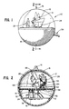
- the ornament 10 constructed in accordance with this invention is seen.
- the ornament 10 is formed in two parts, a hollow hemispherical upper housing member 12 that is transparent, and a hollow hemispherical lower housing member 14 that is opaque.
- the two housing members are joined together to form a hollow spherical housing for the display of an ornamental shape 15.
- the upper housing member 12 has a hanger 16 that allows the spherical housing to be hung from a tree or the like.
- a disc 18 divides the ornament into two chambers, a viewing chamber 20 and a concealing chamber 24.
- the transparency of the upper housing 12 permits viewing of the horse 26 and sleigh 28 of the ornamental shape 15 situated in the viewing chamber 20.
- the sleigh 28 is lit by a lamp 30 that enhances the attractive visual effects of the ornament 10.
- the disc 18 rotates about a central axis 28 and with it rotates the horse 26, sleigh 28 and lamp 30.
- the concealed chamber best seen in figure 2, contains a motor 32 for rotating the disc 18, and circuitry for providing a DC supply to both the motor 32 and the lamp 30.
- a plug 34 is secured to the lower housing member 14 and has contacts 36 and 38 that form electrical power inputs for the ornament.
- the plug 34 is insertable into a socket 40 at one end of a pigtail connector device 42 that will allow the ornament to be plugged into one socket 44 of a string of lights 46.
- the string of lights 46 is connected to a plug 48 for connection to an external conventional 120-volt AC power source.
- the string may include many lights but only two lights 52, 54 and two sockets 56, 58 are shown in Figure 3.
- circuit 60 shown schematically in Figure 3 is used.
- the circuitry is located within the concealing chamber 24 and described in detail in issued patent 4,682,079 assigned to the same assignee as this application and incorporated herein by reference.
- the lamp 30 is positioned on the sleigh 28 away from the axis of rotation of the disc 18.
- the wires 62, 64 supplying current to the lamp do not pass through a central aperture on the disc 18 but instead pass through a pair of apertures 66, 68 situated away from the center of rotation of the disc. Direct connection between the wires 62, 64 and the external power source would result in twisting and possible disconnection of the connection wires on rotation of the disc 18.
- a pair of conducting rings 70, 72 are located on the underside of the rotating disc 18. The rings 70, 72 are in electrical contact with the wires 62, 64 respectively and insulated from one another.
- a pair of brushes 74, 76 insulated from one another make electrical contact between the rings 70, 72 and the circuit providing DC current. As the disc rotates, the brushes 74, 76 trace the paths of a pair of concentric circles that correspond to the rings 70, 72 located on the underside of the disc 18.
- AC current flows in the string of lights and is delivered to the ornament through the pigtail connector device 42.
- the circuit 60 converts the AC supply to a DC supply that feeds the motor 32 and the brush contacts 74, 76.
- the brushes 74, 76 make contact with the rings throughout the entire 360 degrees of rotation of the disc and ornament.
- the rings 70, 72 seen best in Figure 4, are unbroken and therefore provide a continual supply of current to the lamp.
- the rings could, however, be selectively broken as those designated 80, 82 shown in Figure 5. This configuration permits intermittent current to be supplied to the lamp 30 thereby causing the lamp to flicker or flash.
- an illuminated ornament is illustrated in the Figures, the arrangement described is equal suited to the location of load devices other than lamps on the rotating disc.
- the ornament could incorporated a part that moves with respect to the rotating disc, for example a motor vehicle.
- Other motor operated devices could also be positioned on the ornament without restriction on the location of the contacts.
- a musical, or other load device could also be attached to the ornament.
Abstract
An ornament (10) has a viewing chamber (12) with transparent walls for displaying an ornamental object (15) enhanced by a lamp (30) that rotates with it. The mechanism for rotating the ornamental object (15) is contained within a concealing chamber (14) with opaque walls and includes a pair of brushes (74,76) providing sliding contact with a pair of slip rings (70,72) in electrical contact with the lamp (30). The slip rings (70,72) rotate with the ornamental object (15) to supply current to the lamp throughout the 360 degrees of rotation.
Description
- This invention relates to rotating ornaments and more particularly to small tree ornaments or the like which have lights and electrically energizable musical and/or motion producing devices which cooperate to produce highly attractive sensory effects. The ornaments of the invention are easily hung on trees or other supports and connected to a socket of a string of lights and they are safe and highly reliable while being readily and economically manufacturable.
- There are many ornaments that derive at least part of their attractive sensory effects from electric lights or other electrically energizable devices. One example of such an ornament can be found in U.S. patent 4,682,079 which is assigned to the same assignee as this application and which relates to ornaments for installation in a string of lights. These and other ornaments also employ rotation of ornamental elements to enhance their visual appeal.
- A great many different types of lamps have been used or proposed in other technical areas but none of their structures render them suitable for implementation in ornaments designed to be hung on trees and connected in strings of lights, where it it desirable to minimize manufacturing costs and to thereby minimize the cost to a user, while at the same time insuring safe and reliable operation.
- The invention was evolved with the general object of providing ornaments which produced enhanced visual effects and which operate in a simple manner allowing economical manufacture while being safe and reliable.
- In accordance with the invention, an ornament is provided which realizes the foregoing objects and which includes a casing having a dividing wall that divides the casing into a viewing chamber that has transparent walls and a concealing chamber that has opaque walls. A rotatable ornamental member for producing attractive visual effects is disposed within the viewing chamber and is rotated by a motor disposed within the concealing chamber to be concealed from view.
- A lamp or other electrically operated load device is disposed for rotation with the rotatable ornamental member and is energized through connections which are concealed from view and which are disposed in protected positions for maximum safety while being reliable in opeation. Such connections include first and second electrical contacts which are connected to the load device and which are disposed within the concealed chamber and supported from the ornamental member for rotation therewith. Third and fourth electrical contacts are connected to a source of energization and are supported within the concealing chamber in fixed relation to the outer casing. As the ornament rotates with respect to the casing, the third and fourth contacts slidably engage with the first and second contacts respectively.
- The ornament is readily supported from the branch of a tree or other supporting object while being readily connected to a source of electrical power which may preferably be a socket of a string of lights. In accordance with a specific feature of the invention, suspension means extend upwardly from the top of the ornament, preferably in the form of a simple loop. The ornament is energized from a power supply which may preferably be an AC power supply provided by the light string. A further important feature is that the ornament is energizable through a pigtail connector device which is attached to one socket of the string of lights and which may preferably be connected a side portion of the concealing chamber of the oranment. Since the power source is an AC source, circuitry is included to provide a DC current to power the motor and load device. The load device may be any of a number of the possible load devices including a lamp, a motor driven object and a musical device.
- A further feature of the construction is that it can be readily modified for various applications and modes of operation. Instead of a pair of unbroken rings, the first and second contacts may be broken rings that on rotation supply current to the load device intermittently. This type of arrangement is likely to be most desirable when the load device is a lamp as it enables the lamp to flash or flicker depending upon the interval between subsequent supplies of current.
- For a more complete understanding of this invention, reference should now be made to the embodiment illustrated in greater detail in the accompanying drawings and described by way of example only. In the drawings:
- Figure 1 is a perspective view of an ornament of this invention;
- Figure 2 is a section through the ornament of Figure 1;
- Figure 3 is a perspective view of the ornament of Figure 1 showing schematically the connection to a string or lights;
- Figure 4 is a schematic representation of the electric circuitry for supplying current to a light that forms part of the ornament.
- Figure 5 is a schematic representation showing an alternative arrangement of the slip rings of Figure 4.
- Turning to figures 1 and 2,
ornament 10 constructed in accordance with this invention is seen. Theornament 10 is formed in two parts, a hollow hemisphericalupper housing member 12 that is transparent, and a hollow hemisphericallower housing member 14 that is opaque. The two housing members are joined together to form a hollow spherical housing for the display of anornamental shape 15. Theupper housing member 12 has ahanger 16 that allows the spherical housing to be hung from a tree or the like. Adisc 18 divides the ornament into two chambers, aviewing chamber 20 and aconcealing chamber 24. - The transparency of the
upper housing 12 permits viewing of thehorse 26 andsleigh 28 of theornamental shape 15 situated in theviewing chamber 20. Thesleigh 28 is lit by alamp 30 that enhances the attractive visual effects of theornament 10. Thedisc 18 rotates about acentral axis 28 and with it rotates thehorse 26,sleigh 28 andlamp 30. The concealed chamber, best seen in figure 2, contains amotor 32 for rotating thedisc 18, and circuitry for providing a DC supply to both themotor 32 and thelamp 30. - A
plug 34 is secured to thelower housing member 14 and hascontacts plug 34 is insertable into asocket 40 at one end of apigtail connector device 42 that will allow the ornament to be plugged into onesocket 44 of a string oflights 46. The string oflights 46 is connected to aplug 48 for connection to an external conventional 120-volt AC power source. The string may include many lights but only twolights sockets - To provide the DC supply required by the motor and lamp, a
circuit 60, shown schematically in Figure 3 is used. The circuitry is located within theconcealing chamber 24 and described in detail in issued patent 4,682,079 assigned to the same assignee as this application and incorporated herein by reference. - The
lamp 30 is positioned on thesleigh 28 away from the axis of rotation of thedisc 18. Thewires disc 18 but instead pass through a pair ofapertures wires disc 18. In order to prevent this from happening, a pair of conductingrings disc 18. Therings wires brushes rings brushes rings disc 18. - In operation AC current flows in the string of lights and is delivered to the ornament through the
pigtail connector device 42. Thecircuit 60 converts the AC supply to a DC supply that feeds themotor 32 and thebrush contacts brushes rings lamp 30 thereby causing the lamp to flicker or flash. - Although an illuminated ornament is illustrated in the Figures, the arrangement described is equal suited to the location of load devices other than lamps on the rotating disc. For example the ornament could incorporated a part that moves with respect to the rotating disc, for example a motor vehicle. Other motor operated devices could also be positioned on the ornament without restriction on the location of the contacts. Alternatively, a musical, or other load device, could also be attached to the ornament. There is virtually no limit to the different arrangements of ornament and load device that can be accomplished through the mechanism of this invention.
- By providing a mechanism by which the ornament within the casing rotates while the exterior casing remains stationary relative to its surroundings, a simple loop fixture is sufficient to hang the ornament from a tree or the like. This allows the manufacture of the ornament to remain relatively straightforward and for costs to be kept within economically viable limits.
- While one preferred embodiment of this invention is illustrated, it will be understood of course that the invention is not limited to this embodiment. Those skilled in the art to which the invention pertains may make modifications and other embodiments employing the principles of the invention, particularly upon considering the foregoing teachings.
- The embodiments of the invention in which an exclusive property or privilege is claimed are defined as follows:
Claims (14)
- An ornament comprising:
a casing having a dividing wall for providing a viewing chamber having transparent external walls and a concealing chamber having opaque external walls;
a rotatable ornamental member for producing attractive visual effects disposed within said viewing chamber;
a motor disposed in said concealing chamber for rotating said ornamental member;
a motor support member for supporting said motor within said concealing chamber;
first and second electrical contacts insulated one from another, disposed within said concealed chamber and fixed for rotation with said ornamental member;
an electrically operated load device disposed for rotation with said ornamental member within said viewing chamber and having an input and output electrically connected to said first and second electrical contacts respectively;
third and fourth electrical contacts insulated one from another and disposed in said concealing chamber fixed in relation to said outer casing for slidable engagement respectively with said first and second electrical contacts on rotation of said ornamental member; and
a circuit for supplying current to said load device when contact is made between both said first and third electrical contacts and said second and fourth electrical contacts. - The ornament of claim 1 wherein said dividing wall provides support for said ornamental member.
- The ornament of claim 2 wherein said dividing wall is a plate rotatable about an axis.
- The ornament of claim 3 wherein said axis is substantially perpendicular to the plane of said plate.
- The ornament of claim 4 wherein said third and fourth contacts are conductive brushes that rotate relative to said plate tracing respectively first and second patterns relative to said plate.
- The ornament of claim 5 wherein said first and second electrical contacts conform to the path said brushes trace.
- The ornament of claim 6 wherein said first and second patterns are first and second concentric circles centered on the axis of rotation of said plate.
- The ornament of claim 7 wherein said first and second brushes are continually in contact with said first and second circles respectively.
- The ornament of claim 8 wherein said load device is a light.
- The ornament of claim 9 wherein said first and second electrical contacts comprise conductive and insulative portions to provide an intermittent current to said load device.
- The ornament of claim 1 wherein the circuit for supplying current to the load device includes means to connect the load device to a source of AC current.
- The ornament of claim 1 wherein said means to connect the load device to an AC source includes a string of lights and sockets attached to a conventional 120-volt supply, and a pigtail connector providing an electrical connection between said third and fourth electrical contacts and one of the sockets of said string of lights and sockets.
- An ornament comprising:
an outer casing stationary with respect to its surroundings having a transparent section and an opaque section;
a rotatable ornamental member disposed within the transparent section of said casing for producing attractive visual effects;
means to rotate said rotatable ornamental member relative to said outer casing;
an electrically operated load device disposed for rotation with said rotating ornamental member;
first and second electrical contacts fixed in relation to said rotatable ornamental member insulated one from another;
third and fourth electrical contacts insulated one from another and fixed in relation to said outer casing for slidable engagement respectively with said first and second electrical contacts; and
a circuit for supplying current to said load device on contact between said first and third contacts and said second and fourth contacts. - The ornament of claim 13 including a looped member rigidly attached to said outer casing for hanging said ornament from a hook.
Applications Claiming Priority (2)
| Application Number | Priority Date | Filing Date | Title |
|---|---|---|---|
| US07/475,186 US4989120A (en) | 1990-02-05 | 1990-02-05 | Enhanced lighting for ornaments |
| US475186 | 1995-06-07 |
Publications (1)
| Publication Number | Publication Date |
|---|---|
| EP0441051A1 true EP0441051A1 (en) | 1991-08-14 |
Family
ID=23886551
Family Applications (1)
| Application Number | Title | Priority Date | Filing Date |
|---|---|---|---|
| EP90313916A Withdrawn EP0441051A1 (en) | 1990-02-05 | 1990-12-19 | Enhanced lighting for ornaments |
Country Status (5)
| Country | Link |
|---|---|
| US (1) | US4989120A (en) |
| EP (1) | EP0441051A1 (en) |
| JP (1) | JPH0792923A (en) |
| AU (1) | AU7014891A (en) |
| CA (1) | CA2031438A1 (en) |
Cited By (4)
| Publication number | Priority date | Publication date | Assignee | Title |
|---|---|---|---|---|
| WO1998058791A1 (en) * | 1997-06-20 | 1998-12-30 | Ioannis Vavouras | Decorative and promotional item and process of its production in a vacuum forming machine |
| EP1050737A2 (en) * | 1999-05-06 | 2000-11-08 | General Housewares Corp. | Tape measure with outer coating |
| WO2003105638A1 (en) * | 2002-06-12 | 2003-12-24 | Robert Mostowski | A thin-walled, blown glass ornament that opens |
| WO2012032256A1 (en) | 2010-09-06 | 2012-03-15 | Associates Researchers And Engineers | Method for recycling dust from electric steel plants |
Families Citing this family (31)
| Publication number | Priority date | Publication date | Assignee | Title |
|---|---|---|---|---|
| US5097398A (en) * | 1990-11-23 | 1992-03-17 | David Dye | Decorative lighting and rotating display fixture |
| US5108307A (en) * | 1991-02-06 | 1992-04-28 | Seymour Cohen | Support and electrical control device for animated figures |
| US5550319A (en) * | 1991-10-04 | 1996-08-27 | M. H. Segan Limited Partnership | Decorative display and ornament therefor |
| US5303490A (en) * | 1992-06-26 | 1994-04-19 | Steve Yang | Display showing movable ornaments |
| US5280682A (en) * | 1992-08-19 | 1994-01-25 | Ornamotor, Inc. | Ornament and display rotator |
| US5279871A (en) * | 1992-11-05 | 1994-01-18 | M. H. Segan And Company | Action ornament with Christmas tree mounting therefor |
| US5393578A (en) * | 1993-03-24 | 1995-02-28 | Yang; Steve | Christmas motion ornament |
| US5439407A (en) * | 1994-02-01 | 1995-08-08 | Friedel; Joan | Doll with an imaging heart |
| US5451842A (en) * | 1994-03-15 | 1995-09-19 | Chien; Tseng-Lu | Electro-luminescent seasonal light apparatus |
| US5410460A (en) * | 1994-03-24 | 1995-04-25 | Liou; Ching-Chong | Positioning device for a string of decorative lights |
| US5618103A (en) * | 1994-10-05 | 1997-04-08 | Fussell; David A. | Motorized and lighted decorative ornaments |
| US5646383A (en) * | 1995-05-16 | 1997-07-08 | Deem; David Lloyd | Christmas tree ornament power switch |
| US5666750A (en) * | 1995-05-25 | 1997-09-16 | M.H. Segan Limited Partnership | Decorative article with flake circulating means |
| US5513084A (en) * | 1995-07-10 | 1996-04-30 | Simpson; Ted L. | Holiday lighting decoration and method |
| US5642930A (en) * | 1995-09-20 | 1997-07-01 | Brown, Sr.; Jackie C. | Three-dimensional scenery theme lamp |
| US5934785A (en) * | 1997-12-24 | 1999-08-10 | Chen; Ching-Ming | Structure of a light |
| US6022122A (en) * | 1998-08-27 | 2000-02-08 | Limardo; Castro L. | Decorative lamp |
| USD432942S (en) * | 1999-09-22 | 2000-10-31 | Jesus Rodriguez | Christmas decoration |
| US6588748B2 (en) * | 2001-06-12 | 2003-07-08 | Wolow Manufacturing Corp. | Lighted dice |
| US20050158481A1 (en) * | 2002-06-12 | 2005-07-21 | Robert Mostowski | Thin-walled, blown glass ornament that opens |
| US6550928B1 (en) * | 2002-01-14 | 2003-04-22 | Superstar Lighting Co., Ltd. | Light device for generating flash lights |
| US6652349B1 (en) * | 2002-07-08 | 2003-11-25 | Pbc International, Inc. | Animated hanging ornament |
| WO2006094425A1 (en) * | 2005-02-06 | 2006-09-14 | Ben Fan | A continuously rotatable light |
| US20070141945A1 (en) * | 2005-09-29 | 2007-06-21 | Chipman Roger N | Device and method for repelling insects and novelty item |
| US7247076B2 (en) * | 2005-10-14 | 2007-07-24 | Hallmark Cards, Incorporated | Pulse width modulation drive and method for ornaments with movable components |
| CN200981436Y (en) * | 2006-10-26 | 2007-11-28 | 王晓冰 | Automatic rotating article |
| US20090031612A1 (en) * | 2007-07-30 | 2009-02-05 | Eric Heine | Non-chemical fly repellant device |
| DE102009004314B3 (en) * | 2009-01-12 | 2010-09-30 | Krinner Innovation Gmbh | Lighting decoration |
| US8356926B1 (en) | 2009-03-24 | 2013-01-22 | Sanders Harry E | Inflatable externally lighted decoration |
| US20140307425A1 (en) * | 2013-04-11 | 2014-10-16 | Cynthia Price | Solar tree ornament |
| US11559150B2 (en) * | 2020-09-01 | 2023-01-24 | Tracer Imaging Llc | Cube-shaped ornament and photo display |
Citations (2)
| Publication number | Priority date | Publication date | Assignee | Title |
|---|---|---|---|---|
| US1700328A (en) * | 1925-05-11 | 1929-01-29 | Beauty Parlor Designator Mfg C | Display device |
| US4682079A (en) * | 1984-10-04 | 1987-07-21 | Hallmark Cards, Inc. | Light string ornament circuitry |
Family Cites Families (1)
| Publication number | Priority date | Publication date | Assignee | Title |
|---|---|---|---|---|
| US3389248A (en) * | 1965-10-23 | 1968-06-18 | Cable Electric Products Inc | Dwell light |
-
1990
- 1990-02-05 US US07/475,186 patent/US4989120A/en not_active Expired - Fee Related
- 1990-12-04 CA CA002031438A patent/CA2031438A1/en not_active Abandoned
- 1990-12-19 EP EP90313916A patent/EP0441051A1/en not_active Withdrawn
-
1991
- 1991-01-25 JP JP3007420A patent/JPH0792923A/en active Pending
- 1991-01-31 AU AU70148/91A patent/AU7014891A/en not_active Abandoned
Patent Citations (2)
| Publication number | Priority date | Publication date | Assignee | Title |
|---|---|---|---|---|
| US1700328A (en) * | 1925-05-11 | 1929-01-29 | Beauty Parlor Designator Mfg C | Display device |
| US4682079A (en) * | 1984-10-04 | 1987-07-21 | Hallmark Cards, Inc. | Light string ornament circuitry |
Cited By (4)
| Publication number | Priority date | Publication date | Assignee | Title |
|---|---|---|---|---|
| WO1998058791A1 (en) * | 1997-06-20 | 1998-12-30 | Ioannis Vavouras | Decorative and promotional item and process of its production in a vacuum forming machine |
| EP1050737A2 (en) * | 1999-05-06 | 2000-11-08 | General Housewares Corp. | Tape measure with outer coating |
| WO2003105638A1 (en) * | 2002-06-12 | 2003-12-24 | Robert Mostowski | A thin-walled, blown glass ornament that opens |
| WO2012032256A1 (en) | 2010-09-06 | 2012-03-15 | Associates Researchers And Engineers | Method for recycling dust from electric steel plants |
Also Published As
| Publication number | Publication date |
|---|---|
| AU7014891A (en) | 1991-08-08 |
| JPH0792923A (en) | 1995-04-07 |
| US4989120A (en) | 1991-01-29 |
| CA2031438A1 (en) | 1991-08-06 |
Similar Documents
| Publication | Publication Date | Title |
|---|---|---|
| EP0441051A1 (en) | Enhanced lighting for ornaments | |
| US6168282B1 (en) | Electro-luminescent lighting arrangement for a lighting apparatus with a lamp holder | |
| US10247374B2 (en) | Electrically illuminated flame simulator | |
| US4682079A (en) | Light string ornament circuitry | |
| US5829862A (en) | Illuminated lighting structure | |
| US5632550A (en) | Decorative array lighting system | |
| US5327332A (en) | Decorative light socket extension | |
| GB2377327A (en) | Electronic candle | |
| US6341875B1 (en) | Decorative lighting assembly | |
| US5451842A (en) | Electro-luminescent seasonal light apparatus | |
| US6224239B1 (en) | Decorative lamp fixture with icicle shape having interior with plurality of vertically-spaced lights | |
| CN213453436U (en) | Bulb component of electronic candle wick | |
| US3011049A (en) | Christmas tree ornament | |
| USRE32899E (en) | Low voltage lighting system replaceable bulb assembly | |
| US6269566B1 (en) | Glass water ball with light emitting device | |
| US2445079A (en) | Lamp | |
| CN206918769U (en) | A kind of linear modulation | |
| US20040144005A1 (en) | Sound and light swinging device | |
| KR20060118225A (en) | Prayer light implement for buddhist temple | |
| KR200169540Y1 (en) | An Artificial Flower Appartus For Lighting | |
| CN111780020A (en) | Lamp set | |
| JP3056646U (en) | Buddhist altar lighting | |
| JPH06104486A (en) | Lighting device | |
| JPS647405A (en) | Method of hanging lighting appliance and linking wiring fitting of the same | |
| JPS6195008U (en) |
Legal Events
| Date | Code | Title | Description |
|---|---|---|---|
| PUAI | Public reference made under article 153(3) epc to a published international application that has entered the european phase |
Free format text: ORIGINAL CODE: 0009012 |
|
| AK | Designated contracting states |
Kind code of ref document: A1 Designated state(s): BE DE FR GB NL |
|
| STAA | Information on the status of an ep patent application or granted ep patent |
Free format text: STATUS: THE APPLICATION IS DEEMED TO BE WITHDRAWN |
|
| 18D | Application deemed to be withdrawn |
Effective date: 19920215 |