EP0441007A2 - Verfahren zur Realzeitschätzung vom Schwerpunkt eines Flugzeugs - Google Patents
Verfahren zur Realzeitschätzung vom Schwerpunkt eines Flugzeugs Download PDFInfo
- Publication number
- EP0441007A2 EP0441007A2 EP90203502A EP90203502A EP0441007A2 EP 0441007 A2 EP0441007 A2 EP 0441007A2 EP 90203502 A EP90203502 A EP 90203502A EP 90203502 A EP90203502 A EP 90203502A EP 0441007 A2 EP0441007 A2 EP 0441007A2
- Authority
- EP
- European Patent Office
- Prior art keywords
- aircraft
- factor
- setting
- gravity
- flap setting
- Prior art date
- Legal status (The legal status is an assumption and is not a legal conclusion. Google has not performed a legal analysis and makes no representation as to the accuracy of the status listed.)
- Ceased
Links
Images


Classifications
-
- G—PHYSICS
- G01—MEASURING; TESTING
- G01M—TESTING STATIC OR DYNAMIC BALANCE OF MACHINES OR STRUCTURES; TESTING OF STRUCTURES OR APPARATUS, NOT OTHERWISE PROVIDED FOR
- G01M1/00—Testing static or dynamic balance of machines or structures
- G01M1/12—Static balancing; Determining position of centre of gravity
- G01M1/122—Determining position of centre of gravity
- G01M1/125—Determining position of centre of gravity of aircraft
- G01M1/127—Determining position of centre of gravity of aircraft during the flight
Definitions
- This invention relates to aircraft flight control and navigation systems and more specifically, to methods and apparatus for providing a real time estimate of the aircraft center of gravity for use in such systems.
- stabilizer mistrim is utilized in automatic landing procedures to cause a flare-like maneuver in the event of an automatic landing system disconnect caused by a system failure or by the pilot taking manual control of the aircraft.
- the automatic landing system drives the stabilizer in a nose-up direction by supplying a command signal to the elevator trim.
- Opposite elevator is commanded by the system as the stabilizer moves to cancel the pitching moment produced by the stabilizer nose-up command signal.
- a pitch-up moment is generated as the elevator moves to its neutral position.
- the rate of descent (sink rate) is slowed and the pilot is given adequate time to assume control and execute a relatively normal landing (e.g., without an excessively high sink rate or the aircraft nose gear contacting the runway before the main gear).
- Optimal stabilizer mistrim primarily depends on the aircraft approach speed, the flap setting being used during the landing procedure and the location of the aircraft's center of gravity.
- the automatic landing system could employ a fixed or predetermined amount of stabilizer mistrim based upon information gathered during flight tests and/or an estimated worst case aircraft configuration and approach speed.
- a worst case center of gravity location would be assumed and signals representative of the aircraft approach speed and flap setting could be processed to provide stabilizer mistrim that is at least partially compensated for the actual landing profile of the aircraft.
- a need for even occasional substantial nose-down manual command and/or other relatively aggressive manual control of the aircraft gives rise to two relatively important operational considerations of an automatic landing system.
- Some automatic landing systems utilizing worst case center of gravity estimation to establish stabilizer mistrim could, in the event of system disconnect, produce excessive nose-up pitching moment under lightly loaded and aft center of gravity conditions that would cause concern on the part of at least some of the pilots flying aircraft equipped with the system.
- the second consideration is that of passenger comfort and confidence.
- the present invention provides a method of and apparatus for estimating and locating aircraft center of gravity while the aircraft is in flight and executing a maneuver procedure that at least in part depends upon the aircraft's center of gravity. That is, in accordance with the invention, a real time estimate of the aircraft's center of gravity is made available for use by the aircraft flight control and navigation systems so that the command signals generated by those systems are based on an accurate estimate of the aircraft center of gravity rather than a worst case design value.
- the method generally comprises the steps of multiplying a signal representative of the aircraft stabilizer setting by a first multiplicative factor, A1, and adding to the product of stabilizer position and the first multiplicative factor a first additive factor A2.
- the first multiplicative factor A1 and first additive factor A2 are both dependent upon and determined by the aircraft flap setting and the aircraft angle of attack at the time that the center of gravity estimate is being provided.
- the center of gravity estimate is provided during an automatic landing procedure and is utilized to establish stabilizer mistrim.
- the method includes the step of determining whether the aircraft flap setting is a first predetermined value (e.g., 25°) or a second predetermined value (30°).
- A1 is defined by the linear relationship B3AOA+B4
- the above-discussed linear relationships for A1 describe the manner in which aircraft angle of attack relates to the slope of at least two linear approximations that relate aircraft center of gravity to aircraft stabilizer position as a function of aircraft angle of attack at each of the two flap settings (25° and 30°).
- the above-discussed linear relationships for the additive factor A2 describes the manner in which angle of attack relates to the intercept of at least two linear approximations that relate aircraft stabilizer position as a function of aircraft angle of attack at each of the two flap settings (25° and 30°).
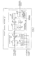
- FIGURE 1 is a block diagram that illustrates a center of gravity estimator (generally denoted by reference numeral 10) that is configured in accordance with the invention and is embodied in an aircraft flight control system 12 along with an elevator controller 14.
- center of gravity estimator 10 operates in conjunction with elevator controller 14, center of gravity estimator 10 provides automatic landing system stabilizer mistrim that is adapted to actual landing conditions.
- the center of gravity estimate produced by center of gravity estimator 10 is produced by multiplying the aircraft stabilizer position by a multiplicative factor A1 (performed by multiplier 16), and by adding to the product of the stabilizer position and factor A1 an additive factor A2 (performed by adder 18 in the arrangement of FIGURE 1).
- the center of gravity estimate is of the form A1S + A2, where S represents the position of the aircraft stabilizer (in degrees).
- the multiplicative factor A1 and the additive factor A2 are respectively provided by a slope generator 20 and an intercept generator 22, each of which operate in accordance with the aircraft flap setting and angle of attack.
- slope generator 20 and intercept generator 22 respectively provide a multiplicative factor A1 and an additive factor A2 that depend upon both the aircraft angle of attack and aircraft flap settings so that the invention provides an estimate of the center of gravity that takes into account aircraft approach speed (reflected in the angle of attack) and aircraft flap setting.
- elevator controller 14 processes the center of gravity estimate, CG EST , to provide an elevator compensation signal M1 CG EST + M2, which is a linear approximation to the relationship between the elevator deflection required for a 1g pull-up maneuver and the position of aircraft center of gravity.
- a multiplier 24 multiplies the center of gravity estimate provided by center of gravity estimator 10 by the multiplicative factor M1 (indicated at block 26).
- An adder 28 provides the sum of the CG EST M1 product and the additive factor M2 (which is indicated at block 30).
- flight control system 12 of FIGURE 1 stores the value of elevator compensation that exists at the time the system engages stabilizer mistrim.
- storing of the current elevator compensation signal is diagrammatically represented by a single pole switch 32, which is activated by the system stabilizer mistrim engage signal.
- Switch 32 is connected to continuously supply the elevator compensation signal to a memory location 34 prior to the time at which switch 32 is activated (before engagement of stabilizer mistrim).
- switch 32 is activated and memory location 34 receives no updated values of elevator compensation signal.
- the value of elevator compensation signal that existed at the time of stabilizer mistrim engagement is latched into memory location 34.
- the multiplicative factor M1 and the additive factor M2 of the elevator compensation signal are normalized relative to the maximum forward center of gravity location for the aircraft that employs the system.
- the appropriate value of elevator command signal is obtained by multiplying the elevator compensation signal by a signal representative of the maximum elevator command that will be required for stabilizer mistrim.
- the maximum elevator command signal is indicated at block 36, with the multiplication of the maximum elevator command signal and the elevator compensation signal being performed by a multiplier 38.
- each automatic landing system or flight control system in which the invention can be embodied generates a maximum elevator command (or equivalent stabilizer command) that is determined on the basis of the aircraft flight characteristics during an automatic landing procedure.
- the maximum elevator command signal is established substantially equal to the elevator (or equivalent stabilizer) control required to offset aircraft nose-down pitching moment caused by ground effects when the aircraft approaches the runway (e.g., ground effects when the aircraft landing gear is 20 ft. above the runway).
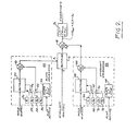
- center of gravity estimator 10 produces a multiplicative factor A1 and an additive factor A2 that depend upon aircraft body angle of attack and flap setting
- a signal representative of the aircraft angle of attack is multiplied by a multiplicative factor B1 or B3 (indicated by multiplier 40) and the product of the multiplicative factor and aircraft angle of attack is summed with an additive factor B2 or B4 (indicated by adder 42).
- multiplicative factor B1 or B3 and selection of additive factor B2 or B4 is made on the basis of the aircraft flap setting.
- large transport and cargo aircraft conventionally utilize one of two flap settings that are identified as 30° flap and 25° flap when executing a landing procedure.
- a readily available flap setting signal is supplied to a flap detector 44.
- multiplicative factor B1 is supplied to multiplier 40 of slope generator 20 and additive factor B2 is supplied to adder 42.
- selection of a multiplicative factor and additive factor on the basis of flap setting is represented by switches 46 and 48, which are operated by flap detector 44 in accordance with aircraft flap setting.
- multiplicative factor B1 (indicated at block 50) is supplied to multiplier 40 via switch 46 and additive factor B2 (indicated at block 52) is supplied to adder 42 of slope generator 20 via switch 48.
- switch 46 supplies multiplicative factor B3 (indicated at block 54) to multiplier 40 and switch 46 supplies additive factor B4 (indicated at block 56) to adder 42.
- the additive factor A2 that is used in estimating the aircraft center of gravity is of the same form as the multiplicative factor A1. That is, for flap setting 25°, and for flap setting 30°, .
- intercept generator 22 of FIGURE 2 is shown as including a multiplier 58 and an adder 60.
- a switch 62 that is activated by a flap detector 64 supplies a multiplicative factor C1 (indicated at block 66) to multiplier 58 when the aircraft flap setting is 25° and supplies a multiplicative factor C3 (indicated at block 68) to multiplier 58 when the aircraft flap setting is 30°.
- a switch 70 that is activated by flap detector 64 supplies an additive factor C2 (indicated at block 72) to adder 60 when the aircraft flap setting is 25° and supplies an additive factor C4 (indicated at block 74) to adder 60 when the aircraft flap setting is 30°.
- the center of gravity estimate provided by the invention is produced by multiplying aircraft stabilizer position by the multiplicative factor A1 and by adding to the product of stabilizer position and A1 the additive factor A2.
- the center of gravity estimate that is produced in this manner is limited so that it does not exceed the maximum forward position for the aircraft that employs the invention and does not exceed the maximum aftmost center of gravity position for that aircraft.
- This limiting operation is indicated in FIGURE 2 by limiter circuit 76, which is connected to receive the center of gravity estimate provided by adder 18.
- FIGURES 1 and 2 can be implemented in various manners using specific logic circuitry or a programmable digital processor.
- modern flight control systems including autopilots and automatic landing systems, basically are digital processors that can be programmed to effect required navigation and flight control laws. Accordingly, in most instances, the invention will be practiced by programming such a flight control system to execute the depicted and discussed control laws.
- suitable multiplicative and additive factors for the practice of the invention can be determined by various analytical and empirical techniques, the currently preferred method of determining the required multiplicative and additive factors can be understood in view of FIGURES 3-7.
- the various relationships that are graphically depicted in these Figures provide a fuller understanding of the manner in which the invention operates to estimate aircraft center of gravity location on the basis of stabilizer position, aircraft body angle of attack and aircraft flap setting.
- the methodology and arrangement of the invention and the values of the above-discussed multiplicative additive factors should be based upon the entire landing envelope of the aircraft that employs the invention.
- the landing envelope for the aircraft of interest consisted of 24 landing conditions in which:
- FIGURE 3 illustrates the stabilizer trim position for each of the 24 above-mentioned landing conditions with stabilizer position being shown relative to the location of the aircraft center of gravity (i.e., 12 data points being shown for maximum forward center of gravity condition and 12 data points be shown for maximum aft center of gravity condition).
- a relatively wide range of stabilizer positions is exhibited relative both to landings with maximum forward center of gravity and landings with maximum aft center of gravity.
- This variation in stabilizer position is caused by variation in aircraft trim angle of attack (which is dependent upon airspeed and weight), flap position, and trim thrust (which is dependent upon aircraft angle of attack, weight and flight path angle).
- FIGURE 4 The relationship between stabilizer position and aircraft angle of attack for the above-discussed 24 landing conditions is depicted in FIGURE 4.
- FIGURE 4 in order to in effect remove the flap and angle of attack effect from the data of FIGURE 3, the data for the 24 landing conditions has been divided into four separate groups or categories on the basis of flap position and center of gravity location. Specifically, in FIGURE 4:
- lines 86, 88, 90 and 92 in FIGURE 4 respectively provide an approximation to the stabilizer position/angle of attack relationship for data points 78, data points 80, data points 82, and data points 84.
- lines 86, 88, 90 and 92 respectively approximate the relationship between stabilizer position and aircraft angle of attack for each of the four above-mentioned categories of landing conditions (flap setting 25°/cg maximum aft; flap setting 30°/cg maximum aft; flap setting 25°/cg maximum forward; and flap setting 30°/cg maximum forward).
- FIGURE 4 confirms generally recognized relationships between stabilizer mistrim and the conditions under which the aircraft is executing an automatic landing. Specifically, at any given angle of attack (combination of ground speed and aircraft weight), the amount of stabilizer trim required for an aft center of gravity condition is substantially greater than the trim required for a landing in which the center of gravity is at the forwardmost position. Further, under both maximum forwardmost and maximum aftmost center of gravity conditions, the stabilizer trim required for a flap setting of 30° is greater than the stabilizer trim required for flap setting 25°. More important, FIGURE 4 quantizes the relationships in a manner that allows a determination of the relationship between aircraft center of gravity and stabilizer position as a function of aircraft angle of attack and flap setting.
- the stabilizer position/angle of attack relationships provided by lines 86, 88, 90 and 92 of FIGURE 4 can be transformed in a manner that provides the relationship between aircraft center of gravity and stabilizer position as a function of aircraft flap setting and angle of attack.
- the angle of attack during an automatic landing procedure is nominally within the range of 3° to 6°, with the exact angle of attack being determined by the glide slope beam angle for the airport at which the landing is being made.
- the stabilizer position for 3° angle of attack landing approach and a 6° angle of attack landing approach can be found at both maximum forward center of gravity and maximum aft center of gravity for each of the two flap settings (30° and 25°).
- the eight values of stabilizer position that are found in this manner are identified in FIGURE 4 by reference numeral 94.
- data points 94 can be used to define four linear relationships between aircraft center of gravity and stabilizer position as a function of flap setting (25° and 30°) and the maximum and minimum angle of attack (3° and 6°).
- FIGURE 5 The four linear relationships between aircraft center of gravity and stabilizer position for the previously discussed 24 landing positions (i.e., the aircraft landing envelope) are shown in FIGURE 5. Specifically, in FIGURE 5, lines 96, 98, 100 and 102 pass through the data points 94 and respectively provide the relationship between aircraft center of gravity location and stabilizer position for:
- the manner in which the relationship between aircraft center of gravity and stabilizer position changes as a function of flap setting and angle of attack can be determined from equations that parametrically express the four center of gravity/stabilizer position relationships of FIGURE 5 (i.e., the equations that define lines 96, 98, 100 and 102 in FIGURE 5).
- equations that parametrically express the four center of gravity/stabilizer position relationships of FIGURE 5 i.e., the equations that define lines 96, 98, 100 and 102 in FIGURE 5.
- angle of attack 3° and 6°
- the two slope values for 30° flap setting and angles of attack equal to 3° and 6° can be used to define a linear relationship that relates angle of attack to the slope of the 30° flap setting center of gravity/stabilizer position relationships of FIGURE 5 (i.e., the linear relationships identified by reference numerals 96 and 100 in FIGURE 5).
- the slope/angle of attack linear relationship for 30° flap setting is identified in FIGURE 6 by reference numeral 106.
- Parametric expressions that separately relate angle of attack to the intercept value of the linear center of gravity/stabilizer position relationships shown in FIGURE 5 can be determined for 25° flap setting and 30° flap setting by using a procedure that is analogous to the procedure described for determining the parametric relationships between aircraft angle of attack and the slope of the center of gravity/stabilizer position relationship.
- the linear intercept/angle of attack relationships for the previously mentioned 24 landing conditions are shown in FIGURE 7, with the intercept/angle of attack relationship for 25° flap setting being identified by reference numeral 108 and the intercept/angle of attack relationship for 30° flap setting being identified by reference numeral 110.
- CG EST an estimate of the location of the aircraft center of gravity
- S represents stabilizer position
- AOA represents aircraft angle of attack
- B1 and B2 respectively represent the slope and intercept values for the 25° flap setting parametric expression that relates angle of attack to the slope of the center of gravity/stabilizer position relationship (i.e., the slope and intercept values of line 104 in FIGURE 6)
- B3 and B4 respectively represent the slope and intercept values for the 30° flap setting parametric expression that relates angle of attack to the slope of the center of gravity/stabilizer position relationship
Landscapes
- Engineering & Computer Science (AREA)
- Aviation & Aerospace Engineering (AREA)
- Physics & Mathematics (AREA)
- General Physics & Mathematics (AREA)
- Traffic Control Systems (AREA)
Applications Claiming Priority (2)
| Application Number | Priority Date | Filing Date | Title |
|---|---|---|---|
| US470577 | 1990-01-26 | ||
| US07/470,577 US5034896A (en) | 1990-01-26 | 1990-01-26 | Method and apparatus for real time estimation of aircraft center of gravity |
Publications (2)
| Publication Number | Publication Date |
|---|---|
| EP0441007A2 true EP0441007A2 (de) | 1991-08-14 |
| EP0441007A3 EP0441007A3 (en) | 1992-08-26 |
Family
ID=23868162
Family Applications (1)
| Application Number | Title | Priority Date | Filing Date |
|---|---|---|---|
| EP19900203502 Ceased EP0441007A3 (en) | 1990-01-26 | 1990-12-21 | Method and apparatus for real time estimation of aircraft center of gravity |
Country Status (2)
| Country | Link |
|---|---|
| US (1) | US5034896A (de) |
| EP (1) | EP0441007A3 (de) |
Cited By (1)
| Publication number | Priority date | Publication date | Assignee | Title |
|---|---|---|---|---|
| US9464958B2 (en) | 2015-01-16 | 2016-10-11 | Bell Helicopter Textron Inc. | Dynamic center of gravity determination |
Families Citing this family (15)
| Publication number | Priority date | Publication date | Assignee | Title |
|---|---|---|---|---|
| US5521827A (en) * | 1994-09-16 | 1996-05-28 | General Electrodynamics Corporation | On-board aircraft weighting and center of gravity determing apparatus and method |
| US5571953A (en) * | 1995-05-15 | 1996-11-05 | The Boeing Company | Method and apparatus for the linear real time estimation of an aircraft center of gravity |
| US6032090A (en) * | 1997-05-06 | 2000-02-29 | General Electrodynamics Corporation | System and method for on-board determination of aircraft weight and load-related characteristics |
| US6466888B1 (en) * | 1999-08-26 | 2002-10-15 | The United States Of America As Represented By The Secretary Of The Navy | Neural network system for estimation of aircraft flight data |
| US6308131B1 (en) | 2000-05-25 | 2001-10-23 | Capital Cargo International Airlines, Inc. | Method of pre-planning the loading of aircraft |
| US6725135B2 (en) * | 2001-09-26 | 2004-04-20 | Stability Dynamics | Vehicle stability operator feedback system |
| US6913228B2 (en) * | 2003-09-04 | 2005-07-05 | Supersonic Aerospace International, Llc | Aircraft with active center of gravity control |
| DE102004056108A1 (de) * | 2004-02-20 | 2005-09-08 | Continental Teves Ag & Co. Ohg | Verfahren zur näherungsweisen Ermittlung der Schwerpunktlage eines Fahrzeuges |
| US7954766B2 (en) * | 2005-06-24 | 2011-06-07 | Sikorsky Aircraft Corporation | System and method for improved rotary-wing aircraft performance with interior/external loads |
| US8260477B2 (en) * | 2007-12-04 | 2012-09-04 | King Fahd University Of Petroleum And Minerals | Method and apparatus for tracking center of gravity of air vehicle |
| US8712607B2 (en) * | 2009-12-07 | 2014-04-29 | Sikorsky Aircraft Corporation | Systems and methods for velocity profile based approach to point control |
| TWI418240B (zh) * | 2010-10-11 | 2013-12-01 | Prodigit Electronics Co Ltd | Electronic Load Simulation Device for Semiconductor Components |
| US8998132B2 (en) | 2011-11-30 | 2015-04-07 | Lockheed Martin Corporation | Aerodynamic wing load distribution control |
| US10962988B2 (en) | 2018-11-01 | 2021-03-30 | Textron Innovations Inc. | Method of determining the center of gravity of an aircraft and a method of fuel/load management based thereon |
| CN113049184B (zh) * | 2021-04-06 | 2024-11-05 | 中国人民解放军63853部队 | 一种质心测量方法、设备及存储介质 |
Family Cites Families (6)
| Publication number | Priority date | Publication date | Assignee | Title |
|---|---|---|---|---|
| US4034334A (en) * | 1975-07-14 | 1977-07-05 | The Boeing Company | Airfoil position range selecting, indicating and warning system for an aircraft |
| US4110605A (en) * | 1977-02-25 | 1978-08-29 | Sperry Rand Corporation | Weight and balance computer apparatus for aircraft |
| US4490802A (en) * | 1981-12-21 | 1984-12-25 | Sperry Corporation | Takeoff weight computer apparatus for aircraft |
| US4545019A (en) * | 1982-06-18 | 1985-10-01 | Sundstrand Corporation | Aircraft in-flight center of gravity measuring system |
| FR2609545B1 (fr) * | 1987-01-08 | 1991-01-04 | Aerospatiale | Procede et systeme pour la determination de la position longitudinale du centre de gravite d'un aeronef pourvu d'un empennage horizontal reglable et application a la surveillance dudit centre de gravite au voisinage du foyer de l'aeronef |
| FR2609546B1 (fr) * | 1987-01-08 | 1991-01-04 | Aerospatiale | Procede et systeme pour la determination de la position longitudinale du centre de gravite d'un aeronef pourvu d'un empennage horizontal reglable |
-
1990
- 1990-01-26 US US07/470,577 patent/US5034896A/en not_active Expired - Lifetime
- 1990-12-21 EP EP19900203502 patent/EP0441007A3/en not_active Ceased
Cited By (1)
| Publication number | Priority date | Publication date | Assignee | Title |
|---|---|---|---|---|
| US9464958B2 (en) | 2015-01-16 | 2016-10-11 | Bell Helicopter Textron Inc. | Dynamic center of gravity determination |
Also Published As
| Publication number | Publication date |
|---|---|
| EP0441007A3 (en) | 1992-08-26 |
| US5034896A (en) | 1991-07-23 |
Similar Documents
| Publication | Publication Date | Title |
|---|---|---|
| US5034896A (en) | Method and apparatus for real time estimation of aircraft center of gravity | |
| US4924401A (en) | Aircraft ground collision avoidance and autorecovery systems device | |
| EP0438816B1 (de) | Automatisches Flugzeuglandesystem mit Vorkehrungen im Fall eines Triebwerkausfalls | |
| EP0253614B1 (de) | System zum Steuern des vertikalen Flugweges und der Fluggeschwindigkeit eines Flugzeuges | |
| US6041273A (en) | Emergency control aircraft system using thrust modulation | |
| US4471439A (en) | Method and apparatus for aircraft pitch and thrust axes control | |
| EP0985993B1 (de) | Flugregelsystem auf Basis totaler Energie | |
| EP0031619B1 (de) | System zum Steuern des vertikalen Flugweges eines Flugzeuges | |
| US5901927A (en) | Ground strike protection function for aircraft autopilot | |
| EP0037159B1 (de) | Auftriebsregelsystem für Flugzeuge | |
| US4347572A (en) | Method and apparatus for an aircraft climb-out guidance system | |
| US5031102A (en) | Method and apparatus for aircraft pitch and thrust axes control | |
| EP0054553B1 (de) | Steuersignal für den abfangübergangsbereich eines flugzeuges | |
| US4763266A (en) | Aircraft flight command and display system | |
| US4314341A (en) | Aircraft automatic pilot with automatic emergency descent control apparatus | |
| US7516014B2 (en) | System and a method for automatic air collision avoidance | |
| US4709336A (en) | Descent flight path control for aircraft | |
| US3327973A (en) | Automatic landing pitch axis control system for aircraft | |
| US6675076B1 (en) | System, autopilot supplement assembly and method for increasing autopilot control authority | |
| US5020747A (en) | Method and apparatus for controlling flare engagement height in automatic landing systems | |
| JPS60154995A (ja) | 航空機の巡航対気速度制御装置 | |
| EP0078688B1 (de) | Geschwindigkeitssteuervorrichtung für Flugzeug | |
| EP0229197B1 (de) | Flugregel- und Anzeigesystem für Windscherung | |
| EP0224279A1 (de) | Vorrichtung und Verfahren zum Generieren von Steuerbefehlen für ein Flugzeug unter Verwendung einer Rückkopplung mit nichtlinearer Verstärkung | |
| TSIKALAS | Space shuttle autoland design |
Legal Events
| Date | Code | Title | Description |
|---|---|---|---|
| PUAI | Public reference made under article 153(3) epc to a published international application that has entered the european phase |
Free format text: ORIGINAL CODE: 0009012 |
|
| AK | Designated contracting states |
Kind code of ref document: A2 Designated state(s): DE FR GB IT NL |
|
| PUAL | Search report despatched |
Free format text: ORIGINAL CODE: 0009013 |
|
| AK | Designated contracting states |
Kind code of ref document: A3 Designated state(s): DE FR GB IT NL |
|
| 17P | Request for examination filed |
Effective date: 19921127 |
|
| 17Q | First examination report despatched |
Effective date: 19930803 |
|
| STAA | Information on the status of an ep patent application or granted ep patent |
Free format text: STATUS: THE APPLICATION HAS BEEN REFUSED |
|
| 18R | Application refused |
Effective date: 19940901 |