EP0440211B1 - An air-fuel ratio control device for a vehicle engine - Google Patents
An air-fuel ratio control device for a vehicle engine Download PDFInfo
- Publication number
- EP0440211B1 EP0440211B1 EP91101229A EP91101229A EP0440211B1 EP 0440211 B1 EP0440211 B1 EP 0440211B1 EP 91101229 A EP91101229 A EP 91101229A EP 91101229 A EP91101229 A EP 91101229A EP 0440211 B1 EP0440211 B1 EP 0440211B1
- Authority
- EP
- European Patent Office
- Prior art keywords
- air
- engine
- operation mode
- fuel ratio
- fuel
- Prior art date
- Legal status (The legal status is an assumption and is not a legal conclusion. Google has not performed a legal analysis and makes no representation as to the accuracy of the status listed.)
- Expired - Lifetime
Links
Images


Classifications
-
- F—MECHANICAL ENGINEERING; LIGHTING; HEATING; WEAPONS; BLASTING
- F02—COMBUSTION ENGINES; HOT-GAS OR COMBUSTION-PRODUCT ENGINE PLANTS
- F02D—CONTROLLING COMBUSTION ENGINES
- F02D41/00—Electrical control of supply of combustible mixture or its constituents
- F02D41/02—Circuit arrangements for generating control signals
- F02D41/04—Introducing corrections for particular operating conditions
- F02D41/06—Introducing corrections for particular operating conditions for engine starting or warming up
- F02D41/062—Introducing corrections for particular operating conditions for engine starting or warming up for starting
- F02D41/065—Introducing corrections for particular operating conditions for engine starting or warming up for starting at hot start or restart
-
- F—MECHANICAL ENGINEERING; LIGHTING; HEATING; WEAPONS; BLASTING
- F02—COMBUSTION ENGINES; HOT-GAS OR COMBUSTION-PRODUCT ENGINE PLANTS
- F02D—CONTROLLING COMBUSTION ENGINES
- F02D41/00—Electrical control of supply of combustible mixture or its constituents
- F02D41/02—Circuit arrangements for generating control signals
- F02D41/04—Introducing corrections for particular operating conditions
- F02D41/06—Introducing corrections for particular operating conditions for engine starting or warming up
- F02D41/068—Introducing corrections for particular operating conditions for engine starting or warming up for warming-up
-
- F—MECHANICAL ENGINEERING; LIGHTING; HEATING; WEAPONS; BLASTING
- F02—COMBUSTION ENGINES; HOT-GAS OR COMBUSTION-PRODUCT ENGINE PLANTS
- F02D—CONTROLLING COMBUSTION ENGINES
- F02D41/00—Electrical control of supply of combustible mixture or its constituents
- F02D41/02—Circuit arrangements for generating control signals
- F02D41/14—Introducing closed-loop corrections
- F02D41/1438—Introducing closed-loop corrections using means for determining characteristics of the combustion gases; Sensors therefor
- F02D41/1473—Introducing closed-loop corrections using means for determining characteristics of the combustion gases; Sensors therefor characterised by the regulation method
- F02D41/1475—Regulating the air fuel ratio at a value other than stoichiometry
-
- F—MECHANICAL ENGINEERING; LIGHTING; HEATING; WEAPONS; BLASTING
- F02—COMBUSTION ENGINES; HOT-GAS OR COMBUSTION-PRODUCT ENGINE PLANTS
- F02D—CONTROLLING COMBUSTION ENGINES
- F02D2200/00—Input parameters for engine control
- F02D2200/50—Input parameters for engine control said parameters being related to the vehicle or its components
- F02D2200/501—Vehicle speed
Landscapes
- Engineering & Computer Science (AREA)
- Chemical & Material Sciences (AREA)
- Combustion & Propulsion (AREA)
- Mechanical Engineering (AREA)
- General Engineering & Computer Science (AREA)
- Electrical Control Of Air Or Fuel Supplied To Internal-Combustion Engine (AREA)
Description
- The present invention relates to an air-fuel ratio control device for a vehicle engine according to the preamble of
claim 1. - A generic air-fuel ratio control device is disclosed in the JP-A-59 196 932. This control device determines the air-fuel ratio by use of the vehicle speed in addition to the temperature of the engine cooling water after an engine startup. If either the vehicle speed or the cooling water temperature exceeds a respective predetermined value, the air-fuel ratio is switched over from rich to lean mixture. However, there might arise operation conditions in which the air-fuel ratio is not conveniently set. Therefore misfires and an unstable combustion could occur.
- Furthermore, in the air-fuel ration control device of the JP-A-59 170 431 the time is counted, but the decision whether a rich or a lean mixture is used does not depend on the vehicle speed. Therefore this control device only works with constant values.
- Engines which are operated on a lean air-fuel mixture having an air-fuel ratio higher than a stoichiometric ratio in the main operating range of the engines are known as lean burn engines. Usually, the lean burn engines are operated on a lean air-fuel mixture, and when acceleration or high load operations are required, the air-fuel ratio of the mixture on which the engine is operated is switched to the stoichiometric ratio or lower (rich) ratio, so that a high engine performance can be obtained without a worsening of the exhaust emissions and fuel efficiency.
- When an engine is not sufficiently warmed up, it is difficult to obtain a stable combustion in the cylinders on a lean air-fuel mixture. Therefore, usually a lean-burn engine is operated on a stoichiometric air-fuel mixture during warming up, and the air-fuel ratio is switched to the lean condition after the engine is fully warmed up. The timing at which the air-fuel ratio is switched to the lean mixture ratio, i.e., the completion of the engine warm up, is usually determined by detecting the temperature of the engine coolant, such as cooling water.
- For example, JP-A 58-48727 discloses an engine operated on a stoichiometric air-fuel ratio mixture when the temperature of the engine cooling water is lower than the predetermined value, and when the temperature of the cooling water reaches the predetermined value, the air-fuel ratio is switched to lean ratio.
- Nevertheless, the actual factor which influences the condition of the combustion in the cylinders is the wall temperature of the combustion chamber, not the cooling water temperature, and therefore, if the air-fuel ratio of the mixture is determined by the cooling water temperature only, in some cases a stable combustion cannot be obtained. For example, if the engine is stopped after being fully warmed up, and then restarted within a relatively short time, sometimes the combustion becomes unstable and misfires occur. This is caused by the difference in the cooling speeds of the cooling water and the wall of the combustion chamber. Namely, due to a high specific heat, the cooling speed of the cooling water is low but the cooling speed of the wall of the combustion chamber is relatively high. Therefore, when the engine is stopped while in a fully warmed up condition, the temperature of the cooling water drops very slowly; in practice, the temperature of the cooling water does not change for several minutes. Therefore, in the prior art, if the engine is re-started after a short stop of several minutes, the air fuel ratio is made lean immediately after the engine start up, since the cooling water temperature is still higher than the predetermined value. Nevertheless, the wall temperature of the combustion chamber drops more rapidly, and even within short stops of several minutes, the wall temperature of the combustion chamber becomes too low for a stable combustion of the lean air-fuel mixture. Consequently, in the prior art, when the engine is re-started after a short stop, an unstable combustion or misfire sometimes occurs due to an inappropriate switching to the lean mixture.
- To solve this problem, the switching of air-fuel ratio of air-fuel mixture fed to engine must be controlled in accordance with the wall temperature of the combustion chamber, but a reliable measurement of the wall temperature of the combustion chamber with conventional devices is very difficult, and thus a control in accordance with the wall temperature is not considered practical.
- It is an object of the present invention to further develop the air-fuel ratio control device according to the preamble of
claim 1 such that misfires and an unstable combustion can be prevented. - This object is achieved by the features indicated in the characterizing portion of
claim 1. - Advantageous further developments are set out in the dependent claims.
- The air-fuel ratio control device can prevent an inappropriate changeover to a lean air-fuel mixture when the wall temperature of the combustion chamber is low, and thus can prevent the occurrence of misfires and an unstable combustion.
- The present invention will be more fully understood from the description of a preferred embodiment of the invention set forth below, together with the accompanying drawings.
- In the drawings:
- Fig. 1 is a schematically illustrated view of an engine;
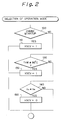
- Fig. 2 is a flow chart of the selecting of the operation mode of the engine;
- Fig. 3 is a diagram illustrating the relationship between the vehicle speed setting V₀ and the time after engine start up;
- Fig. 4 is a flow chart of the routine for actuating the swirl control valve in accordance with the selected operation mode;
- Fig. 5 is a flow chart of the routine for adjusting the air-fuel ratio of the mixture in accordance with the selected operation mode; and,
- Fig. 6 is a flow chart of the routine for adjusting the ignition timing in accordance with the selected operation mode.
- Fig. 1 illustrates an embodiment of the air-fuel ratio control device according to the present invention.
- Referring to Fig. 1,
reference numeral 10 represents a cylinder block of an engine, and 12 is a cylinder bore. As shown in the figure, each cylinder of the engine is provided with twointake ports 12a, 12b and twoexhaust ports inlet valves 16a, 16b andexhaust valves - The first inlet port 12a is formed as a helical port which deflects the inlet air flow to thereby generate a swirl in the cylinder. The
second inlet port 12b is formed as a conventional straight type inlet port. Theinlet ports 12a and 12b are connected to asurge tank 22 and athrottle valve 24 via anintake air passage 20, and afuel injector 26 is mounted on theintake air passage 20 near each cylinder. Theexhaust ports -
Reference numeral 30 represents a distributor which supplies high voltage electricity to spark plugs (not shown) at the respective cylinders. - Each straight
type inlet port 12b is equipped with a swirl control valve 32 which is in either the open or closed position. When the swirl control valve 32 is in the closed position, thestraight port 12b is closed and all of the inlet air flows into the engine cylinder through the helical port 12a. Accordingly, the inlet air flow forms a strong swirl in the engine cylinder, and thus a stable combustion of the lean air-fuel mixture can be obtained. Conversely, when the swirl control valve 32 is in the open position, the inlet air flows into the cylinder through both of theinlet ports 12a, 12b, whereby the volume of the inlet air is increased. - The swirl control valve 32 comprises a valve plate 32a connected to an
actuator 38 via alever 34 and arod 36. - The
actuator 38 comprises a diaphragm 40, andspring 41 biasing the diaphragm downward. When a negative pressure is introduced to the upper side of the diaphragm 40, the diaphragm 40 and therod 36 are moved upward against the force of thespring 41 and the swirl control valve 32 is moved to the open position. Conversely, when the atmospheric pressure is introduced to the upper side of the diaphragm 40, the swirl control valve 32 is urged downward to the closed position, by thespring 41. - The chamber formed at the upper side of the diaphragm 40 is connected to the pressure port 22a formed on the
surge tank 22 via a timing control valve 42, a solenoid operated three-way valve 44, and acheck valve 46. The timing control valve 42 includes anorifice 42a and acheck valve 42b arranged in parallel to each other. The timing control valve 42 maintains the opening speed of the swirl control valve 32 at an appropriate level by controlling the speed of the introduction of the atmospheric air to the upper side of the diaphragm 40. Thecheck valve 46 maintains the negative pressure on the upper side of the diaphragm 40 when the pressure in thesurge tank 22 becomes higher. - The solenoid operated three
way valve 44 comprises threeports port 44a is communicated with theport 44c, and the upper side of the diaphragm 40 is open to the pressure port 22a of thesurge tank 22. On the other hand, when the solenoid is energized, theport 44a is communicated to theport 44b, and the upper side of the diaphragm 40 is open to the atmosphere, through afilter 48 and theorifice 42a of the timing control valve 42. - An
electronic control unit 50 is provided to control the swirl control valve 32 by energizing and de-energizing the solenoid of the threeway valve 44. Theelectronic control unit 50 is constructed as a digital computer which comprises a ROM (read only memory) 52, a RAM (random access memory) 53, a CPU (central processing unit) 54, aninput port 55 and anoutput port 56. TheROM 52, the RAM 33, theCPU 54, theinput port 55 and theoutput port 56 are interconnected by abidirectional bus 51. - The
electronic control unit 50 also controls the amount of fuel injected by afuel injector 26 and the ignition timing according to the invention. Accordingly, theoutput port 56 of theelectronic control unit 50 is connected to thefuel injector 26 and the solenoid operated threeway valve 44, via acorresponding drive circuit distributor 30 via aignition circuit 62. Anabsolute pressure sensor 72, which generates an output voltage proportional to the absolute pressure PM in thesurge tank 22, is mounted on thesurge tank 22, and the output voltage of theabsolute pressure sensor 72 is input to theinput port 55 via anAD convertor 64. -
Crank angle sensors distributor 30. The firstcrank angle sensor 74 detects a reference position of the crank shaft rotation and generates a pulse signal at, for example, each 720 degrees rotation of the crank shaft. The secondcrank angle sensor 76 detects the rotation angle of the crank shaft and generates a pulse signal at, for example, each 30 degrees rotation of the crank shaft. - The outputs of the
crank angle sensors input port 55, and the engine speed NE is calculated from the pulse output by thecrank angle sensor 76 to theCPU 54. - A
throttle sensor 79 is mounted on thethrottle valve 24 and generates an output voltage proportional to the degree of opening of thethrottle valve 24. The output of thethrottle sensor 79 is input to theinput port 55 via anAD converter 65.Reference numeral 80 indicates a starter switch which transmits a start signal to theinput port 55 when the starting motor (not shown) of the engine is energized. Theelectronic control unit 50 is provided with abuiltin clock 54a, which generates a clock pulse for theCPU 54. When the startup of the engine is completed, theelectronic control unit 50 starts to count the pulses of theclock 54a, to thereby measure the time elapsed after startup. A speed sensor 82 generates an output voltage proportional to a speed of the vehicle driven by the engine. Acoolant temperature sensor 84, which generates an output voltage proportional to the cooling water temperature, is mounted on the engine. The outputs of the speed sensor 82 and thecoolant temperature sensor 84 are input to theinput port 55 via correspondingAD converters - Fig. 2 illustrates the routine for selecting the operation mode of the engine, i.e., the air-fuel ratio of the air-fuel mixture supplied to the engine. This routine is processed by the
electronic control unit 50 as a part of the main routine for controlling the engine. - Referring to Fig. 2, in
step 100 it is determined whether the engine is being started. It is determined that the engine is being started when a startup signal is transmitted from thestarter switch 80 and the engine speed is lower than a predetermined value (for example, 400 rpm). If the engine is being started, the routine proceeds to step 110, in which a flag XSCV is set. The flag XSCV represents the operation mode of the engine, and when the flag XSCV is set, the engine is switched to operate on a rich air-fuel mixture. - If it is determined that the engine was already started, i.e., if the engine speed is higher than the predetermined value, in
step 120 it is determined whether the cooling water temperature THW is lower than the predetermined value (for example, 80°C). The cooling water temperature is calculated from the output of thecoolant temperature sensor 84. - If the temperature THW is lower than or equal to the predetermined value, the flag XSCV is set in
step 130, and if the temperature THW is higher than the predetermined value, the routine proceed to step 140. Instep 140, it is determined whether the vehicle speed Va detected by the speed sensor 82 is lower than a value V₀. The value V₀ is determined as a function of the time T₀ after the completion of the startup of the engine. The time T₀ is measured by counting the clock pulses of theclock 54a. Fig. 3 shows a typical relationship of the value V₀ and the time T₀. In this embodiment, the relationship of V₀ and T₀ in Fig. 3 is stored in theROM 52 in the form of a numeric table. The speed V₀ is determined from the table by theCPU 54. - If the vehicle speed Va is higher than or equal to V₀ , the flag XSCV is reset in
step 150, and when the flag XSCV is reset, the engine is switched to operate on a lean air-fuel mixture. If the vehicle speed Va is less than V₀ , the routine is ended without changing the setting of the flag XSCV. - As shown in Fig. 2, this routine always selects the rich mixture operation mode during engine startup, and does not switch to the lean mixture operation mode unless the vehicle speed Va become higher than or equal to V₀ , even if the cooling water temperature is higher than the predetermined value. As shown in Fig. 3, value V₀ is lowered at the time T₀ , and becomes zero after a predetermined time has elapsed (for example, 300 secs). Therefore, after this predetermined time has elapsed and the cooling water temperature is higher than the predetermined value, the operation mode is automatically switched to a lean mixture operation, regardless of the vehicle speed Va.
- In this embodiment, V₀ is considered to be a parameter related to the wall temperature of the combustion chamber of the engine. It is considered that the wall temperature of the combustion chamber is a function of the time after startup and an accumulated value of engine operation load after startup. The vehicle speed can be conveniently used as a parameter indicating the accumulated value of the engine operation load, as it represents the total work done by the engine for accelerating the vehicle from a standstill to a certain speed.
- There are other parameters which relate to the accumulated engine operation load; for example, parameters such as accumulated values of the engine revolutions, of the intake manifold pressure, or the total amount of fuel injected can be used, but the engine revolutions and the intake manifold pressure are widely varied during the engine operation, and due to these variations, the accumulated values of these parameters include relatively large errors. Also, the total amount of the injected fuel is largely influenced by the cooling water temperature, and a complicated correction process is required for the calculation. The vehicle speed can be conveniently and reliably used because these problems do not arise when estimating the wall temperature of the combustion chamber thereby.
- In this embodiment, as understood from
step 140 of Fig. 2, once the vehicle speed Va exceeds the value Va and the operation mode is switched to the lean mixture mode, a switching of the operation mode (i.e., from the lean mixture mode to the rich mixture mode) does not occur even if the vehicle speed Va becomes lower than the value V₀. - Fig. 4 illustrates the routine for switching the position of the swirl control valve according to the selected operation mode. This routine is processed by the
electronic control unit 50 by sequential interruptions at predetermined intervals. - Referring to Fig. 4, in
step 180 it is determined whether the flag XSCV is set. The flag XSCV represents the selected operation mode and is set or reset by the routine in Fig. 2. - When the flag XSCV is set in
step 180, then instep 185 the solenoid of the threeway valve 44 is de-energized. As explained above, when the solenoid is de-energized, the pressure port 22a of thesurge tank 22 is in communication with the upper side of the diaphragm 40 of theactuator 38, via thecheck valve 42b, and therefore, the diaphragm 40 is moved upward against the force exerted by thespring 41. This movement of the diaphragm 40 causes the swirl control valve 32 to move to the closed position, and when the swirl control valve 32 is in the closed position, the negative pressure in theactuator 38 is maintained by thecheck valve 46, and thus the swirl control valve 32 is held in the closed position even when the pressure in thesurge tank 22 becomes higher. - When the flag XSCV is reset, in
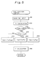
step 190 the solenoid of the threeway valve 44 is de-energized and the upper side of the diaphragm 40 of theactuator 38 is then open to the atmosphere through thefilter 48 and thecheck valve 42a of the timing control valve 42. Accordingly, the diaphragm 40 is urged downward by thespring 41 and the swirl control valve 32 is moved to the open position. The opening speed of the swirl control valve 32 is appropriately controlled by theorifice 42a, and the closing speed thereof is maintained by thecheck valve 42b. - Fig. 5 illustrates the routine for determining the amount of the fuel to be injected, to adjust the air-fuel ratio of the mixture in accordance with the operation mode selected by the routine in Fig. 2. This routine is processed immediately before the fuel is injected, when the crank angle detected by the
sensors - Referring to Fig. 5, in
step 210, the intake air manifold pressure (the pressure in the surge tank 22) PM, the engine speed NE, the cooling water temperature THW are read by thesensors step 220, a standard amount of fuel injection Tp is determined as a function of the manifold pressure PM and the engine speed NE. In this embodiment, the standard amount Tp is stored in theROM 52 of theelectronic control unit 50, in the form of a numeric table. Note that if the standard amount TP is provided, the air-fuel ratio becomes stochiometric ratio. Then, instep 230, it is determined whether the cooling water temperature THW is lower than a predetermined temperature (for example, 50°C). If the THW is lower than the predetermined value, instep 250, a corrected amount of fuel injection TAU is determined by multiplying a correction factor FWL with the standard amount of fuel injection Tp. The correction factor FWL is determined as a function of the cooling water temperature, which is stored in theROM 52 in the form of a numeric table. The purpose of the correction factor FWL is to make the air-fuel ratio of the mixture rich so that a stable combustion is obtained when the cooling water temperature is low. Note that the correction factor is larger than the value "1.0". Then, instep 280, the fuel injection time Ti is calculated on the basis of the determined TAU, and thefuel injector 26 is opened for the time Ti so that the required amount of fuel TAU is injected. - When the cooling water temperature THW is higher than or equal to the predetermined value in
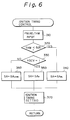
step 230, then instep 240 it is determined whether the flag XSCV is set. When the flag XSCV is set, then the corrected amount of fuel injection TAU is decided instep 260 by multiplying a rich mixture correction factor Fs with the standard amount of fuel injection Tp. The rich mixture correction factor Fs is a constant or variable value used to set the corrected amount of fuel injection so that the air-fuel ratio of the mixture becomes lower (richer) than or equal to stoichiometric air-fuel ratio. Note that the correction factor is equal to or larger than the value "1.0". After the TAU is set instep 260, the fuel injection time Ti is set instep 260. If the flag XSCV is reset instep 240, the corrected amount of fuel injection TAU is determined instep 270 by multiplying a lean mixture correction factor FLFAN with the standard amount of fuel injection Tp. The lean mixture correction factor FLEAN is a constant or variable value used to set the corrected amount of fuel injection TAU so that the air-fuel ratio of the mixture becomes higher than the stoichiometric air-fuel ratio. Note that the lean mixture correction factor FLEAN has the value that is smaller than the value "1.0". - Fig. 6 illustrates the routine for selecting the ignition timing in accordance with the operation mode selected by the routine in Fig. 2. This routine is processed by the
electronic control unit 50 as a part of the main routine for controlling the engine. - Referring to Fig. 6,
steps steps - SAWL is a function of PM, NE and THW, which is stored in
ROM 52 in the form of a numeric table, and provides an ignition timing suitable for the rich mixture established by the correction factor FWL instep 250 of Fig. 5. - Similarly, SAS (step 350) and SALEAN (step 360) are selected as the ignition timing setting SA, in accordance with the setting of the flag XSCV.
- SAS and SALEAN are the functions of PM and NE, and provide an ignition timing suitable for the rich mixture established by
step 260 and the lean mixture established bystep 270 in Fig. 2 respectively. Since the air-fuel ratio of the mixture and the ignition timing, as well as the position of the swirl control valve, are switched in accordance with the operation mode selected by the routine in Fig. 2, a stable combustion can be obtained with both a rich and a lean mixture. - According to the present invention, when the engine is started, the operation mode is not switched to the operation on the lean air-fuel mixture unless it is judged that the wall temperature of the combustion chamber is high enough to support a stable combustion with the lean air-fuel mixture. Therefore, the misfires caused by an inappropriate switching to lean mixture when the engine is restarted at a high cooling water temperature can be prevented, and a stable operation of the engine is assured under all operating conditions.
- An air-fuel ratio control device for a vehicle engine is proposed, by which the air-fuel ratio of the air-fuel mixture supplied to a vehicle engine is changed to a lean mixture when the engine coolant temperature is higher than a predetermined value and the vehicle speed is higher than a value determined by a time elapsed after engine startup.
Claims (9)
- An air-fuel ratio control device for a vehicle engine comprising
means (84) for detecting a temperature of an engine coolant,
operation mode selecting means (50) for selecting operation modes of said engine, said operation mode selecting means (50) selecting a rich mixture operation mode in which said engine is operated on a rich air-fuel mixture having an air-fuel ratio lower than or equal to a stoichiometric ratio when said engine coolant temperature is lower than a predetermined value, and said operation mode selecting means (50) selecting a lean mixture operation mode in which said engine is operated on a lean air-fuel mixture having an air-fuel higher than said stoichiometric ratio when said coolant temperature is higher than said predetermined value,
air-fuel ratio setting means (26, 44) for adjusting an air-fuel ratio of an air-fuel mixture in accordance with said operation mode selected by said operation mode selecting means (50),
startup detecting means (80, 55) for detecting a startup (100) of said engine,
speed detecting means (82) for detecting a speed of a vehicle driven by said engine and
prohibiting means (54) for prohibiting a selection by said operation mode selecting means of said lean mixture operation mode during a period from said engine startup (100) until the speed (Va) of the vehicle reaches a predetermined value (V₀)
characterized by
time measuring means (54a) for measuring a time elapsed after completion of said engine startup (100), wherein said predetermined value (V₀) of the vehicle speed is determined as a decreasing function of said time elapsed after completion of said engine startup (100). - An air-fuel ratio control device according to claim 1, characterized in that said predetermined value (V₀) of the vehicle speed becomes zero after a predetermined time has elapsed from the completion of said startup of the engine.
- An air-fuel ratio control device according to claim 1, characterized in that said startup detecting means (80,55) determines that the engine startup is completed when the engine speed reaches a predetermined value after the engine startup is initiated.
- An air-fuel ratio control device according to claim 3, characterized in that said operation mode selecting means (50) select a rich mixture operation mode during the startup of the engine, regardless of said engine coolant temperature.
- An air-fuel ratio control device according to claim 1, characterized in that once the speed of the vehicle has reached said predetermined value (V₀), said prohibiting means (54) do not prohibit the selection of the lean mixture mode even if the speed of the vehicle thereafter becomes lower than said predetermined value (V₀).
- An air-fuel ratio control device according to claim 1, characterized in that said air-fuel ratio setting means (26,44) include fuel injectors (26) and a fuel injection control means (60) which control an amount of fuel needed to obtain an air-fuel ratio in accordance with the operation mode selected by said operation mode selecting means (50).
- An air-fuel ratio control device according to claim 4, characterized in that said air-fuel ratio setting means (26,44) further includes ignition timing control means which controls a timing of ignition in accordance with the operation mode selected by said operation mode selecting means (50).
- An air-fuel ratio control device according to claim 7, characterized in that said air-fuel ratio setting means (26,44) further includes means for generating an inlet air swirl within engine cylinders when the lean mixture operation mode is selected by said operation mode selecting means (50).
- An air-fuel ratio control device according to claim 8, characterized in that said means for generating an inlet air swirl includes helical ports (12a) and straight ports (12b) of the engine cylinders for inlet air, and swirl control valves (32) which close inlet air passages to said straight ports (12b) when the lean mixture operation mode is selected, so that inlet air to the engine flows into the engine cylinders only through said helical ports (12a).
Applications Claiming Priority (2)
| Application Number | Priority Date | Filing Date | Title |
|---|---|---|---|
| JP18971/90 | 1990-01-31 | ||
| JP2018971A JPH03225045A (en) | 1990-01-31 | 1990-01-31 | Air-fuel ratio control device for internal combustion engine |
Publications (3)
| Publication Number | Publication Date |
|---|---|
| EP0440211A2 EP0440211A2 (en) | 1991-08-07 |
| EP0440211A3 EP0440211A3 (en) | 1993-03-03 |
| EP0440211B1 true EP0440211B1 (en) | 1995-12-27 |
Family
ID=11986532
Family Applications (1)
| Application Number | Title | Priority Date | Filing Date |
|---|---|---|---|
| EP91101229A Expired - Lifetime EP0440211B1 (en) | 1990-01-31 | 1991-01-30 | An air-fuel ratio control device for a vehicle engine |
Country Status (4)
| Country | Link |
|---|---|
| US (1) | US5092297A (en) |
| EP (1) | EP0440211B1 (en) |
| JP (1) | JPH03225045A (en) |
| DE (1) | DE69115722T2 (en) |
Families Citing this family (6)
| Publication number | Priority date | Publication date | Assignee | Title |
|---|---|---|---|---|
| JP3005818B2 (en) * | 1990-12-25 | 2000-02-07 | 本田技研工業株式会社 | Engine start fuel supply control device |
| JP2737426B2 (en) * | 1991-03-08 | 1998-04-08 | 日産自動車株式会社 | Fuel injection control device for internal combustion engine |
| DE4433299A1 (en) * | 1994-09-19 | 1996-03-21 | Bosch Gmbh Robert | Method and device for idle adjustment of an internal combustion engine |
| DE19755299A1 (en) * | 1997-12-12 | 1999-06-17 | Man Nutzfahrzeuge Ag | Process for NO¶x¶ reduction in mixture-compressing internal combustion engines |
| JP3952733B2 (en) * | 2001-10-22 | 2007-08-01 | 日産自動車株式会社 | Diesel engine exhaust purification control system |
| JP4840244B2 (en) * | 2007-04-26 | 2011-12-21 | 株式会社デンソー | Air-fuel ratio control device and engine control system |
Family Cites Families (12)
| Publication number | Priority date | Publication date | Assignee | Title |
|---|---|---|---|---|
| JPS5848727A (en) * | 1981-09-09 | 1983-03-22 | Toyota Motor Corp | Air-fuel ratio controlling apparatus for internal- combustion engine |
| JPS59162329A (en) * | 1983-03-07 | 1984-09-13 | Nippon Carbureter Co Ltd | Fuel control method of engine |
| JPS59170431A (en) * | 1983-03-18 | 1984-09-26 | Toyota Motor Corp | Control of air-fuel ratio of internal-combustion engine |
| JPS59196932A (en) * | 1983-04-25 | 1984-11-08 | Nissan Motor Co Ltd | Air-fuel ratio controlling apparatus for internal-combustion engine |
| US4594986A (en) * | 1984-01-20 | 1986-06-17 | Mazda Motor Corporation | Fuel supply arrangement for internal combustion engine |
| JPS60211651A (en) * | 1984-04-05 | 1985-10-24 | Matsushita Electric Ind Co Ltd | Magnetic recording and reproducing device |
| JPS60230532A (en) * | 1984-04-28 | 1985-11-16 | Toyota Motor Corp | Air-fuel ratio controller for internal-combustion engine |
| JPH0674761B2 (en) * | 1985-01-25 | 1994-09-21 | スズキ株式会社 | Fuel injection control method |
| JPH07116964B2 (en) * | 1986-02-14 | 1995-12-18 | 本田技研工業株式会社 | Fuel supply control method after starting of internal combustion engine |
| DE3609600C2 (en) * | 1986-03-21 | 2001-05-23 | Bosch Gmbh Robert | Hot start raising method for internal combustion engines |
| JPS639649A (en) * | 1986-06-30 | 1988-01-16 | Nissan Motor Co Ltd | Air-fuel ratio controller for internal combustion engine |
| JPH0751905B2 (en) * | 1986-12-27 | 1995-06-05 | 本田技研工業株式会社 | Fuel supply control method after starting of internal combustion engine |
-
1990
- 1990-01-31 JP JP2018971A patent/JPH03225045A/en active Pending
-
1991
- 1991-01-28 US US07/646,663 patent/US5092297A/en not_active Expired - Fee Related
- 1991-01-30 EP EP91101229A patent/EP0440211B1/en not_active Expired - Lifetime
- 1991-01-30 DE DE69115722T patent/DE69115722T2/en not_active Expired - Fee Related
Also Published As
| Publication number | Publication date |
|---|---|
| EP0440211A2 (en) | 1991-08-07 |
| US5092297A (en) | 1992-03-03 |
| DE69115722D1 (en) | 1996-02-08 |
| JPH03225045A (en) | 1991-10-04 |
| EP0440211A3 (en) | 1993-03-03 |
| DE69115722T2 (en) | 1996-05-30 |
Similar Documents
| Publication | Publication Date | Title |
|---|---|---|
| US4403584A (en) | Method and apparatus for optimum control for internal combustion engines | |
| US5979397A (en) | Control apparatus for direct injection spark ignition type internal combustion engine | |
| US5586537A (en) | Fuel property detecting apparatus for internal combustion engines | |
| US5499607A (en) | Fuel characteristic detecting system for internal combustion engine | |
| US5881552A (en) | Control system for internal combustion engines and control system for vehicles | |
| US4444168A (en) | Engine idling speed control method and apparatus | |
| US5934247A (en) | Engine deceleration control device | |
| EP0924420B1 (en) | Torque controller for internal combustion engine | |
| US4457282A (en) | Electronic control for fuel injection | |
| US4785785A (en) | Fuel injection control device for an internal combustion engine with throttle opening detection means | |
| EP0440173B1 (en) | Method and apparatus for controlling torque generated in an internal combustion engine | |
| JPH05214989A (en) | Control device for engine | |
| EP1284363B1 (en) | Ignition timing control device for internal combustion engine | |
| EP0440211B1 (en) | An air-fuel ratio control device for a vehicle engine | |
| EP0894960B1 (en) | Idling speed control system of internal combustion engine | |
| JPH09250387A (en) | Fuel injection control method for internal combustion engine | |
| US5697340A (en) | Engine cold startup controller | |
| US4915078A (en) | Fuel injection control device of an internal combustion engine | |
| EP0447765B1 (en) | An air-fuel ratio control device for an engine | |
| EP1167730B1 (en) | Device for controlling rotational speed of internal combustion engine | |
| JP3466192B2 (en) | Control device for fuel metering of internal combustion engine | |
| US4785779A (en) | Internal combustion engine control apparatus | |
| EP0161611B1 (en) | Method and apparatus for controlling air-fuel ratio in internal combustion engine | |
| JP2000136737A (en) | Reverse rotation preventing device for internal combustion engine | |
| JPH0430358Y2 (en) |
Legal Events
| Date | Code | Title | Description |
|---|---|---|---|
| PUAI | Public reference made under article 153(3) epc to a published international application that has entered the european phase |
Free format text: ORIGINAL CODE: 0009012 |
|
| 17P | Request for examination filed |
Effective date: 19910130 |
|
| AK | Designated contracting states |
Kind code of ref document: A2 Designated state(s): DE FR GB |
|
| PUAL | Search report despatched |
Free format text: ORIGINAL CODE: 0009013 |
|
| AK | Designated contracting states |
Kind code of ref document: A3 Designated state(s): DE FR GB |
|
| 17Q | First examination report despatched |
Effective date: 19931210 |
|
| GRAA | (expected) grant |
Free format text: ORIGINAL CODE: 0009210 |
|
| AK | Designated contracting states |
Kind code of ref document: B1 Designated state(s): DE FR GB |
|
| REF | Corresponds to: |
Ref document number: 69115722 Country of ref document: DE Date of ref document: 19960208 |
|
| ET | Fr: translation filed | ||
| PLBE | No opposition filed within time limit |
Free format text: ORIGINAL CODE: 0009261 |
|
| STAA | Information on the status of an ep patent application or granted ep patent |
Free format text: STATUS: NO OPPOSITION FILED WITHIN TIME LIMIT |
|
| 26N | No opposition filed | ||
| PGFP | Annual fee paid to national office [announced via postgrant information from national office to epo] |
Ref country code: FR Payment date: 19980109 Year of fee payment: 8 |
|
| PGFP | Annual fee paid to national office [announced via postgrant information from national office to epo] |
Ref country code: GB Payment date: 19980121 Year of fee payment: 8 |
|
| PGFP | Annual fee paid to national office [announced via postgrant information from national office to epo] |
Ref country code: DE Payment date: 19980206 Year of fee payment: 8 |
|
| PG25 | Lapsed in a contracting state [announced via postgrant information from national office to epo] |
Ref country code: GB Free format text: LAPSE BECAUSE OF NON-PAYMENT OF DUE FEES Effective date: 19990130 |
|
| GBPC | Gb: european patent ceased through non-payment of renewal fee |
Effective date: 19990130 |
|
| PG25 | Lapsed in a contracting state [announced via postgrant information from national office to epo] |
Ref country code: FR Free format text: LAPSE BECAUSE OF NON-PAYMENT OF DUE FEES Effective date: 19990930 |
|
| PG25 | Lapsed in a contracting state [announced via postgrant information from national office to epo] |
Ref country code: DE Free format text: LAPSE BECAUSE OF NON-PAYMENT OF DUE FEES Effective date: 19991103 |
|
| REG | Reference to a national code |
Ref country code: FR Ref legal event code: ST |