EP0439665A1 - Welding machine for flat bars - Google Patents
Welding machine for flat bars Download PDFInfo
- Publication number
- EP0439665A1 EP0439665A1 EP19900107184 EP90107184A EP0439665A1 EP 0439665 A1 EP0439665 A1 EP 0439665A1 EP 19900107184 EP19900107184 EP 19900107184 EP 90107184 A EP90107184 A EP 90107184A EP 0439665 A1 EP0439665 A1 EP 0439665A1
- Authority
- EP
- European Patent Office
- Prior art keywords
- board
- hold
- support
- welding
- edge
- Prior art date
- Legal status (The legal status is an assumption and is not a legal conclusion. Google has not performed a legal analysis and makes no representation as to the accuracy of the status listed.)
- Granted
Links
Images


Classifications
-
- B—PERFORMING OPERATIONS; TRANSPORTING
- B23—MACHINE TOOLS; METAL-WORKING NOT OTHERWISE PROVIDED FOR
- B23K—SOLDERING OR UNSOLDERING; WELDING; CLADDING OR PLATING BY SOLDERING OR WELDING; CUTTING BY APPLYING HEAT LOCALLY, e.g. FLAME CUTTING; WORKING BY LASER BEAM
- B23K11/00—Resistance welding; Severing by resistance heating
- B23K11/06—Resistance welding; Severing by resistance heating using roller electrodes
- B23K11/061—Resistance welding; Severing by resistance heating using roller electrodes for welding rectilinear seams
- B23K11/062—Resistance welding; Severing by resistance heating using roller electrodes for welding rectilinear seams for welding longitudinal seams of tubes
- B23K11/063—Lap welding
Definitions
- a known circuit board welding machine of this type (DE magazine “Industrie-excellentr” 83/1989, p. 30/31) works according to the roller seam welding technique with two electrode rollers which act on the edges of the circuit boards which overlap in a narrow area with such pressure and under such conditions electrical current can be passed on, so that an overlapping pinch seam is formed.
- the required relative movement between the welding device and the two plates is generated in that the plates in the direction of the weld with respect to the electrode rollers be advanced.
- the required overlap of the boards can be adjusted, for example, by inserting the edges of the boards to be welded together into a groove in a so-called Z-rail, which is then withdrawn.
- the profile of the Z-rail is designed in such a way that the two boards cannot collide when their edges are pushed over one another and that once and for all it is determined which of the two edges comes to rest on the other.
- this specification is particularly important if the blanks consist of sheets of different thickness, quality or surface treatment.
- the invention is therefore based on the object of guiding the edges of boards to be welded to one another without a Z-rail in such a way that they reach the required overlap position during a feed movement transverse to the longitudinal direction of the intended weld seam.
- a support device is arranged between the two clamping devices for supporting the edge to be welded on the board supplied on one of the two feed tables, which has a support position in which it is to be welded Supports the edge of the board in question, can be moved into a rest position in which it can be placed on the edge of the other board.
- the support device according to the invention even prevents boards, which are not quite flat, from colliding against one another when pushed together with the edges of their edges to be welded together. In its rest position, the support device no longer exerts any force on the board it previously supported; the board edges to be welded together then lie on one another in a plane which is determined solely by the arrangement of the clamping devices.
- the support device can expediently be rotated back and forth about an axis parallel to the intended weld seam between the support position and the rest position.
- a hold-down device between the two clamping devices arranged the edge of the other board to be welded.
- This development of the invention has the particular advantage that it can be chosen from case to case, which of the two board edges to be welded to one another should lie on the other.
- stop surfaces do not need to be provided or, if present, not to be used as such if the two feed tables can be fed in CNC-controlled transversely to the intended weld seam and each carry at least one clamping device for a blank and one stop bar each, which is parallel to the intended weld seam arranged and movable from a stop position for pre-adjusting the associated board into a rest position.
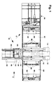
- the machine shown has a central machine part 10 with a stand 12, from which an upper arm 14 and a lower arm 16 project in the same direction.
- the lower arm 16 rests on additional supports 18.
- a stationary welding device 20 is arranged on the middle machine part 10; this includes an upper electrode roller 22, which is pressed by means of a pressing device 24 adjustable in height near the free end of the upper arm 14, and a lower electrode roller 26 which is mounted perpendicularly below the upper electrode roller 22 on the lower arm 16.
- the two electrode rollers 22 and 26 are each rotatable about a horizontal axis and are arranged at least approximately in a common vertical plane, which is also the central plane M of the entire welding machine.
- a welding carriage 28 is guided so as to be horizontally displaceable in said center plane M and can be moved by means of a drive 30 from a rest position near the stand 12 shown in full lines in FIG. 2 to an end position indicated by dash-dotted lines.
- a clamping device 32 and 34 is arranged on both sides of the central plane M and parallel thereto.
- the two clamping devices 32 and 34 are designed and arranged symmetrically with respect to the central plane and each have one or more lower clamping jaws 36 and one or more upper clamping jaws 38.
- the lower clamping jaws 36 are fastened to a lower beam 40 of the welding carriage 28.
- the upper clamping jaws 38 are height-adjustable in accordance with the arrows y in FIG.
- Hooks 44 which are mounted eccentrically on a shaft 46 which extends normal to the central plane M and in turn are mounted on the lower beam 40, serve for locking.
- the shaft 46 can be rotated back and forth between a locking position by means of a piston-cylinder unit 48 and a release position.
- the hooks 44 In the locking position, which is shown in FIG. 6, the hooks 44 connect the lower beam 40 to the upper beam 42 in such a way that its front end shown in FIG. 6 cannot bend upwards when the clamping devices 32 and 34 are actuated.
- the hooks 44 leave a gap between the lower bar 40 and the upper bar 42.
- a lower support 49 Arranged in the center plane M, that is between the two clamping devices 32 and 34, is a lower support 49 which projects horizontally from the stator 12 and serves as a current-carrying feed line to the lower electrode roller 26.
- a support device 50 is mounted on the carrier 49 and has a shaft 52 lying horizontally in the central plane M.
- two mutually symmetrical, strip-shaped support bodies 54 are fastened, which consist of hardened steel, extend approximately over the entire length of the shaft 52 and each have a deflecting surface 56 and a stop surface 58 and a support surface 60.
- the abutment surface 58 extends at right angles to the support surface 60, and this includes an obtuse angle of approximately 160 ° with the deflecting surface 56.
- Each of the support bodies 54 can be brought into a support position according to FIG. 4a or into a rest position according to FIG. 4b by rotating the shaft 52.
- An actuating device 62 is provided for rotating the shaft 52, for example a piston-cylinder unit, which is connected to the shaft 52 via a lever 64.
- the support position and the rest position of the support body 54 on the left in FIGS. 3 and 4 are defined by adjustable stops 66 and 68 in the example shown.
- a hold-down device 70 is mounted on the carrier 69 and has a shaft 72 lying horizontally in the central plane M with two hold-down bodies 74 that are symmetrical to one another.
- the hold-down bodies 74 are also made of hardened steel and, in a manner corresponding to the support bodies 54, each have a deflecting surface 76, a stop surface 78 and a support surface 80 between them. According to FIGS.
- the shaft 72 is in an angular position set in which their right hold-down body 74 assumes a hold-down position. From this rotational angle position, the shaft 72 can be rotated either by hand or with a device that corresponds to the actuating device 62 into a position in which the left-hand hold-down body 74 is effective in FIGS. 3, 4a and 4b. This rotation is connected with an opposite rotation of the shaft 52 and leads to the fact that the left holding-down body 74 is opposed to the right supporting body 54 at an angle.
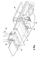
- a feed table 82 or 84 is arranged on each side of the middle machine part 10. These two feed tables 82 and 84 can be stationary and have, for example, roller tracks or ball guides on their upper side, which make it possible for each plate P 1 or P r in the direction of the arrow x 1 or x r in the direction of the central part 10 to be almost frictionless move. In the example shown, however, the two feed tables 82 and 84 are themselves deliverable in the direction x l and x r and are each designed for prefixing a board P l or P r .
- each of the feed tables 82 and 84 has a stop bar 86, which extends parallel to the central plane M, and thus parallel to the intended welding direction z and can be lowered by means of an actuator 88 from its stop position shown in FIG. 5 into an ineffective position.
- clamping devices 90 and pressing devices 92 are arranged at a distance from the stop bar 86 for one of the boards P 1 and P r .
- each of the feed tables 82 and 84 carries a vertical mandrel 94 with which a specific position of the relevant board P l or P r can be determined.
- each of them is placed, for example by means of a handling device 96 of the type indicated in FIG. 1, on one of the feed tables 82 and 84 and, according to FIG. 5, with the edge K which is the edge to be welded of the relevant board, placed against the associated stop bar 86 and held there by the associated pressing devices 92, while the board is displaced until it also rests on the associated mandrel 94, whereby the board with respect to the associated feed table 82 or 84 is clearly defined.
- the associated jigs 90 are actuated so that each of the plates P l and P r is clamped on the associated feed table 82 and 84 respectively.
- actuators 88 are actuated so that the stop bars 86 come into their rest position and the edges of the plates P 1 and P r to be welded together are exposed.
- the feed tables 82 and 84 are numerically controlled from their clamping position shown in FIGS. 1 and 5 moved at right angles to the center plane M in the direction x l and X r .
- the edge to be welded slides the board P l according to Fig. 3 and 4a on the deflecting surface 56 of the left supporting body 54, which occupies its supporting position.
- the board P l comes into a welding position in which its edge lies on the support surface 60 and the edge K of this edge reaches a position in the immediate vicinity of the stop surface 78 of the right hold-down body 74.
- this stop surface 78 is not effective as such; it is only required if the feed table 82 is not CNC-controlled, but instead is formed, for example, by a roller conveyor.
- the board P r After it has been adjusted and clamped on the feed table 84, is moved to the left by its movement in the direction of the arrow x r , its edge to be welded being pressed down by the deflecting surface 76 of the right hold-down body 74 is and the free edge of this edge almost reaches the stop surface 58 of the left support body 54.
- the edge of the board P r then abuts the horizontal contact surface 80 of the right hold-down body 74 from below.
- the mutual assignment of the left support body 54 and the right hold-down body 74 clearly stipulates that the edge of the right plate P r comes to lie below the edge of the left plate P l .
- the support device 50 is now rotated counterclockwise from the support position according to FIG. 4a into the rest position according to FIG. 4b, in which the boards P 1 and P r are no longer touched by the support device 50.
- the edge of the board P l springs slightly downward and then lies in a plane which is defined by the two clamping devices 32 and 34, on the edge of the board P r , the two boards also no longer being touched by the holding-down device 70 .
- the two clamping devices 32 and 34 are actuated, as a result of which the two plates P l and P r are fixed with the intended overlap in relation to one another and to the welding carriage 38.
- the clamping devices 90 and pressing devices 92 on both feed tables 82 and 84 are rendered ineffective, and these are moved back into their starting position according to FIG. 1.
- the welding carriage 28 is set in motion in the welding direction z together with the two clamped plates P l and P r .
- the welding begins according to a specific welding current-electrode force program. It is also possible to insert the plates P l and P r into the clamping devices 32 and 34 in such a way that the front edges of the weld seam come to lie directly under the electrodes 22 and 26. In this case, the welding movement of the welding carriage 28 and the welding current electrode force program start simultaneously.
- the clamping devices 32 and 34 are opened so that they release the boards P l and P r . Then the hooks 44 are pivoted downward, and the welded plates P l and P r are pulled out forward between the lower bar 40 and the upper bar 42.
Abstract
Description
Die Erfindung betrifft eine Platinenschweißmaschine mit
- einem mittleren Maschinenteil, an dem zwei Klemmvorrichtungen für je eine Platine sowie eine Schweißvorrichtung zum Verschweißen von einander überlappenden Rändern der Platinen angeordnet sind,
- einem Antrieb zum Erzeugen einer Relativbewegung längs der vorgesehenen Schweißnaht zwischen der Schweißvorrichtung und den Klemmvorrichtungen und
- zwei auf je einer Seite des mittleren Maschinenteils angeordneten Zuführtischen, auf denen sich je eine Platine quer zur vorgesehenen Schweißnaht durch je eine der Klemmvorrichtungen hindurch in eine Überlappungsstellung zuführen läßt.
- a middle machine part, on which two clamping devices for one board each and a welding device for welding overlapping edges of the boards are arranged,
- a drive for generating a relative movement along the intended weld between the welding device and the clamping devices and
- two feed tables arranged on each side of the middle machine part, on each of which a plate can be fed transversely to the intended weld seam through one of the clamping devices into an overlapping position.
Eine bekannte Platinenschweißmaschine dieser Gattung (DE-Zeitschrift "Industrie-Anzeiger" 83/1989, S. 30/31) arbeitet nach der Rollnahtschweißtechnik mit zwei Elektrodenrollen, die auf den einander in einem schmalen Bereich überlappenden Rändern der Platinen mit solchem Druck und unter solchem elektrischem Strom abwälzbar sind, daß eine Überlapptquetschnaht entsteht. Dabei wird die erforderliche Relativbewegung zwischen der Schweißvorrichtung und den beiden Platinen dadurch erzeugt, daß die Platinen in Richtung der Schweißnaht in bezug auf die Elektrodenrollen vorgeschoben werden. Es ist jedoch auch möglich, bei einer Platinenschweißmaschine der beschriebenen Gattung die Platinen während des Schweißens ortsfest anzuordnen und die Schweißvorrichtung die erforderliche Längsbewegung in bezug auf die Platinen durchführen zu lassen.A known circuit board welding machine of this type (DE magazine "Industrie-Anzeiger" 83/1989, p. 30/31) works according to the roller seam welding technique with two electrode rollers which act on the edges of the circuit boards which overlap in a narrow area with such pressure and under such conditions electrical current can be passed on, so that an overlapping pinch seam is formed. The required relative movement between the welding device and the two plates is generated in that the plates in the direction of the weld with respect to the electrode rollers be advanced. However, it is also possible to arrange the boards stationary in a board welding machine of the type described during the welding and to have the welding device carry out the required longitudinal movement with respect to the boards.
In jedem Fall ist es erforderlich, die miteinander zu verschweißenden Ränder der Platinen derart übereinander zu schieben, daß sie sich auf ihrer gesamten Länge um einen vorgegebenen Betrag überlappen. Dieser Betrag muß vor allem dann besonders genau eingehalten werden, wenn eine Überlapptquetschtnaht geschweißt werden soll.In any case, it is necessary to slide the edges of the boards to be welded together so that they overlap by a predetermined amount over their entire length. This amount must be adhered to particularly precisely if an overlap crimped seam is to be welded.
Die erforderliche Überlappung der Platinen läßt sich beispielsweise dadurch einstellen, daß man die miteinander zu verschweißenden Ränder der Platinen in je eine Nut einer sogenannten Z-Schiene einschiebt, die anschließend zurückgezogen wird. Das Profil der Z-Schiene ist so gestaltet, daß die beiden Platinen beim Übereinanderschieben ihrer Ränder nicht gegeneinanderstoßen können und daß ein für allemal festgelegt ist, welcher der beiden Ränder auf dem anderen zu liegen kommt. Diese Festlegung ist mit Rücksicht auf die spätere Verwendung der miteinander verschweißten Platinen vor allem dann von Bedeutung, wenn die Platinen aus Blechen unterschiedlicher Dicke, Qualität oder Oberflächenbehandlung bestehen.The required overlap of the boards can be adjusted, for example, by inserting the edges of the boards to be welded together into a groove in a so-called Z-rail, which is then withdrawn. The profile of the Z-rail is designed in such a way that the two boards cannot collide when their edges are pushed over one another and that once and for all it is determined which of the two edges comes to rest on the other. With regard to the later use of the blanks welded together, this specification is particularly important if the blanks consist of sheets of different thickness, quality or surface treatment.
Das bisher übliche Zurückziehen der Z-Schiene, nachdem die Bleche in ihrer Überlapptstellung festgelegt worden sind, ist umständlich. Wenn man aber darauf verzichtet hat, die Z-Schiene vor Beginn des Schweißens zurückzuziehen und stattdessen die Platinen durch Verschieben der Klemmvorrichtungen erst während des Schweißens aus der Z-Schiene herausbewegt hat, ist es vor allem bei längeren Schweißnähten nicht immer möglich gewesen, eine vorgesehene Überlappungsbreite mit der angestrebten Genauigkeit einzuhalten.The usual retraction of the Z-rail after the sheets have been fixed in their overlapping position is cumbersome. If, however, one has refrained from pulling the Z-rail back before starting the welding and instead has moved the plates out of the Z-rail by moving the clamping devices only during welding, it was not always possible, especially with longer weld seams, to provide one Adhere to the overlap width with the desired accuracy.
Der Erfindung liegt deshalb die Aufgabe zugrunde, die miteinander zu verschweißenden Ränder von Platinen ohne eine Z-Schiene derart zu führen, daß sie bei einer Zustellbewegung quer zur Längsrichtung der vorgesehenen Schweißnaht in die erforderliche Überlappungsstellung gelangen.The invention is therefore based on the object of guiding the edges of boards to be welded to one another without a Z-rail in such a way that they reach the required overlap position during a feed movement transverse to the longitudinal direction of the intended weld seam.
Die Aufgabe ist erfindungsgemäß ausgehend von einer Platinenschweißmaschine der eingangs beschriebenen Gattung dadurch gelöst, daß zwischen den beiden Klemmvorrichtungen zum Abstützen des zu verschweißenden Randes der auf einem der beiden Zuführtische zugeführten Platine eine Stützvorrichtung angeordnet ist, die aus einer Stützstellung, in der sie den zu verschweißenden Rand der betreffenden Platine abstützt, in eine Ruhestellung bewegbar ist, in der sie diesen Rand sich auf den Rand der anderen Platine auflegen läßt.The object is achieved on the basis of a plate welding machine of the type described in the introduction in that a support device is arranged between the two clamping devices for supporting the edge to be welded on the board supplied on one of the two feed tables, which has a support position in which it is to be welded Supports the edge of the board in question, can be moved into a rest position in which it can be placed on the edge of the other board.
Die erfindungsgemäße Stützvorrichtung hindert selbst Platinen, die nicht ganz eben sind, beim Zusammenschieben mit den Kanten ihrer miteinander zu verschweißenden Ränder gegeneinander zu stoßen. In ihrer Ruhestellung übt die Stützvorrichtung keinerlei Kraft mehr auf die von ihr zuvor abgestützte Platine aus; die miteinander zu verschweißenden Platinenränder liegen dann in einer Ebene aufeinander, die allein durch die Anordnung der Klemmvorrichtungen festgelegt ist.The support device according to the invention even prevents boards, which are not quite flat, from colliding against one another when pushed together with the edges of their edges to be welded together. In its rest position, the support device no longer exerts any force on the board it previously supported; the board edges to be welded together then lie on one another in a plane which is determined solely by the arrangement of the clamping devices.
Die Stützvorrichtung ist zweckmäßigerweise um eine zur vorgesehenen Schweißnaht parallele Achse zwischen der Stützstellung und der Ruhestellung hin- und herdrehbar.The support device can expediently be rotated back and forth about an axis parallel to the intended weld seam between the support position and the rest position.
Zusätzlich zu der Stützvorrichtung, mit der sich der Rand einer der Platinen abstützen läßt, ist bei einer bevorzugten Ausführungsform der Erfindung zwischen den beiden Klemmvorrichtungen ferner eine Niederhaltvorrichtung für den zu verschweißenden Rand der anderen Platine angeordnet. Diese Anordnung einer Stützvorrichtung und einer Niederhaltevorrichtung ermöglicht es, ein Gegeneinanderstoßen der Kanten der miteinander zu verschweißenden Platinenränder schon dann sicher zu vermeiden, wenn jeder dieser Platinenränder nur sehr geringfügig aus der zugehörigen Platinenebene angehoben bzw. abgesenkt wird.In addition to the support device with which the edge of one of the boards can be supported, in a preferred embodiment of the invention there is also a hold-down device between the two clamping devices arranged the edge of the other board to be welded. This arrangement of a support device and a hold-down device makes it possible to reliably avoid abutting the edges of the board edges to be welded to one another if each of these board edges is raised or lowered only very slightly from the associated board plane.
Die im vorstehenden beschriebenen Merkmale sind vorzugsweise dadurch weitergebildet, daß
- die Stützvorrichtung zwei symmetrisch angeordnete Stützkörper aufweist,
- die Niederhaltevorrichtung zwei symmetrisch angeordnete Niederhaltekörper aufweist, und
- Stützvorrichtung und Niederhaltevorrichtung gegenläufig um je eine zur vorgesehenen Schweißnaht parallele Achse zwischen zwei Endstellungen hin- und herdrehbar sind, in denen jeweils ein Stützkörper einem Niederhaltekörper schräg gegenübersteht.
- the support device has two symmetrically arranged support bodies,
- the hold-down device has two symmetrically arranged hold-down bodies, and
- Support device and hold-down device can be rotated in opposite directions about an axis parallel to the intended weld seam between two end positions, in each of which a support body is diagonally opposite a hold-down body.
Diese Weiterbildung der Erfindung hat den besonderen Vorteil, daß von Fall zu Fall gewählt werden kann, welcher von zwei miteinander zu verschweißenden Platinenrändern auf dem anderen liegen soll.This development of the invention has the particular advantage that it can be chosen from case to case, which of the two board edges to be welded to one another should lie on the other.
Die erfindungsgemäße Stützvorrichtung und Niederhaltevorrichtung können auch dazu dienen, die Überlappungsbreite der miteinander zu verschweißenden Platinenränder festzulegen. Zu diesem Zweck kann vorgesehen sein, daß
- jeder Stützkörper eine Abweisfläche für die von ihm zu stützende Platine sowie eine Anschlagfläche für die von einem Niederhaltekörper niederzuhaltende Platine aufweist, und
- jeder Niederhaltekörper eine Abweisfläche für die von ihm niederzuhaltende Platine sowie eine Anschlagfläche für die von einem Stützkörper zu stützende Platine aufweist.
- each support body has a deflecting surface for the board to be supported by it and a stop surface for the board to be held down by a hold-down body, and
- each hold-down body has a deflecting surface for the board to be held down by it and a stop surface for the board to be supported by a support body.
Solche Anschlagflächen brauchen indessen nicht vorgesehen oder, falls vorhanden, nicht als solche benutzt zu werden, wenn die beiden Zuführtische CNC-gesteuert quer zur vorgesehenen Schweißnaht zustellbar sind und je mindestens eine Aufspannvorrichtung für eine Platine sowie je eine Anschlagleiste tragen, die parallel zur vorgesehenen Schweißnaht angeordnet und aus einer Anschlagstellung zum Vorjustieren der zugehörigen Platine in eine Ruhestellung bewegbar ist.However, such stop surfaces do not need to be provided or, if present, not to be used as such if the two feed tables can be fed in CNC-controlled transversely to the intended weld seam and each carry at least one clamping device for a blank and one stop bar each, which is parallel to the intended weld seam arranged and movable from a stop position for pre-adjusting the associated board into a rest position.
Ein Ausführungsbeispiel der Erfindung wird im folgenden anhand schematischer Zeichnungen mit weiteren Einzelheiten erläutert. Es zeigen:
- Fig. 1
- die Draufsicht einer erfindungsgemäßen Platinenschweißmaschine,
- Fig. 2
- die Seitenansicht in Richtung des Pfeils II in Fig. 1,
- Fig. 3
- die Schrägansicht eines Teils der Maschine in Richtung des Pfeils III in Fig. 1,
- Fig. 4
- a den senkrechten Schnitt IV-IV in Fig. 2 in einer ersten Betriebsstellung,
- Fig. 4b
- denselben Schnitt in einer zweiten Betriebsstellung,
- Fig. 5
- die Schrägansicht in Richtung des Pfeils V in Fig. 1 und
- Fig. 6
- die Schrägansicht in Richtung des Pfeils VI in Fig. 2.
- Fig. 1
- the top view of a circuit board welding machine according to the invention,
- Fig. 2
- the side view in the direction of arrow II in Fig. 1,
- Fig. 3
- the oblique view of part of the machine in the direction of arrow III in Fig. 1,
- Fig. 4
- a the vertical section IV-IV in Fig. 2 in a first operating position,
- Fig. 4b
- the same cut in a second operating position,
- Fig. 5
- the oblique view in the direction of arrow V in Fig. 1 and
- Fig. 6
- the oblique view in the direction of arrow VI in Fig. 2nd
Die dargestellte Maschine hat ein mittleres Maschinenteil 10 mit einem Ständer 12, von dem ein oberer Ausleger 14 und ein unterer Ausleger 16 in gleicher Richtung wegragen. Der untere Ausleger 16 ruht auf zusätzlichen Stützen 18. Am mittleren Maschinenteil 10 ist eine ortsfeste Schweißvorrichtung 20 angeordnet; dazu gehören eine obere Elektrodenrolle 22, die mittels einer Anpreßvorrichtung 24 höheneinstellbar nahe dem freien Ende des oberen Auslegers 14 gelagert ist, und eine untere Elektrodenrolle 26, die senkrecht unterhalb der oberen Elektrodenrolle 22 am unteren Ausleger 16 gelagert ist. Die beiden Elektrodenrollen 22 und 26 sind um je eine waagerechte Achse drehbar und sind mindestens annähernd in einer gemeinsamen senkrechten Ebene angeordnet, die zugleich Mittelebene M der gesamten Schweißmaschine ist.The machine shown has a
Am unteren Ausleger 16 ist ein Schweißwagen 28 in der genannten Mittelebene M waagerecht verschiebbar geführt und mittels eines Antriebs 30 aus einer in Fig. 2 mit vollen Linien abgebildeten Ruhestellung nahe dem Ständer 12 in eine mit strichpunktierten Linien angedeutete Endstellung bewegbar. Auf dem Schweißwagen 28 ist beiderseits der Mittelebene M und parallel zu dieser je eine Klemmvorrichtung 32 und 34 angeordnet. Die beiden Klemmvorrichtungen 32 und 34 sind in bezug zur Mittelebene symmetrisch gestaltet und angeordnet und haben je einen oder mehrere untere Klemmbacken 36 sowie je einen oder mehrere obere Klemmbacken 38. Die unteren Klemmbacken 36 sind an einem Unterbalken 40 des Schweißwagens 28 befestigt. Die oberen Klemmbacken 38 sind entsprechend den Pfeilen y in Fig. 4a höhenverstellbar, beispielsweise mittels hydraulischer Kolbenzylindereinheiten, an einem waagerechten Oberbalken 42 abgestützt, der sich in der Mittelebene M erstreckt, an seinem dem Ständer 12 benachbarten Ende starr am Schweißwagen 28 befestigt ist und an seinem gegenüberliegenden Ende gemäß Fig. 6 mit dem Unterbalken 40 verriegelbar ist.On the
Zum Verriegeln dienen Haken 44, die exzentrisch an einer Welle 46 gelagert sind, welche sich normal zur Mittelebene M erstreckt und ihrerseits am Unterbalken 40 gelagert ist. Die Welle 46 ist mittels einer Kolbenzylindereinheit 48 hin- und herdrehbar zwischen einer Verriegelungsstellung und einer Lösestellung. In der Verriegelungsstellung, die in Fig. 6 abgebildet ist, verbinden die Haken 44 den Unterbalken 40 derart mit dem Oberbalken 42, daß dessen in Fig. 6 dargestelltes vorderes Ende sich bei Betätigung der Klemmvorrichtungen 32 und 34 nicht nach oben biegen kann. In der Öffnungsstellung, die in Fig. 2 mit strichpunktierten Linien angedeutet ist, lassen die Haken 44 einen Spalt zwischen dem Unterbalken 40 und dem Oberbalken 42 frei.
In der Mittelebene M, also zwischen den beiden Klemmvorrichtungen 32 und 34, ist ein waagerecht vom Ständer 12 wegragender unterer Träger 49 angeordnet, der als stromführende Zuleitung zur unteren Elektrodenrolle 26 dient. Am Träger 49 ist eine Stützvorrichtung 50 gelagert, die eine waagerecht in der Mittelebene M liegende Welle 52 aufweist. An der Welle 52 sind zwei zueinander symmetrische, leistenförmige Stützkörper 54 befestigt, die aus gehärtetem Stahl bestehen, sich annähernd über die gesamte Länge der Welle 52 erstrecken und je eine Abweisfläche 56 sowie je eine Anschlagfläche 58 und je eine Auflagefläche 60 aufweisen. Die Anschlagfläche 58 erstreckt sich im rechten Winkel zur Auflagefläche 60, und diese schließt mit der Abweisfläche 56 einen stumpfen Winkel von ungefähr 160° ein. Jeder der Stützkörper 54 läßt sich durch Drehen der Welle 52 wahlweise in eine Stützstellung gemäß Fig. 4a oder in eine Ruhestellung gemäß Fig. 4b bringen. Zum Drehen der Welle 52 ist eine Betätigungsvorrichtung 62 vorgesehen, beispielsweise eine Kolbenzylindereinheit, die über einen Hebel 64 mit der Welle 52 verbunden ist. Durch verstellbare Anschläge 66 und 68 sind im dargestellten Beispiel die Stützstellung und die Ruhestellung des in Fig. 3 und 4 linken Stützkörpers 54 festgelegt.Arranged in the center plane M, that is between the two
Senkrecht über der Stützvorrichtung 50, also ebenfalls zwischen den beiden Klemmvorrichtungen 32 und 34, ist ein waagerecht vom Ständer 12 wegragender oberer Träger 69 angeordnet, der als stromführende Zuleitung zur oberen Elektrodenrolle 22 dient. Am Träger 69 ist eine Niederhaltevorrichtung 70 gelagert, die eine waagerecht in der Mittelebene M liegende Welle 72 mit zwei zueinander symmetrischen Niederhaltekörpern 74 aufweist. Die Niederhaltekörper 74 sind ebenfalls aus gehärtetem Stahl und haben in entsprechender Weise wie die Stützkörper 54 je eine Abweisfläche 76, je eine Anschlagfläche 78 und je eine zwischen diesen liegende Auflagefläche 80. Gemäß Fig. 3, 4 und 4a ist die Welle 72 in einer Drehwinkelstellung festgelegt, in der ihr rechter Niederhaltekörper 74 eine Niederhaltestellung einnimmt. Aus dieser Drehwinkelstellung ist die Welle 72 entweder von Hand oder mit einer Vorrichtung, die der Betätigungsvorrichtung 62 entspricht, in eine Stellung drehbar, in der ihr in Fig. 3, 4a und 4b linker Niederhaltekörper 74 wirksam ist. Diese Drehung ist mit einer gegenläufigen Drehung der Welle 52 verbunden und führt dazu, daß dem linken Niederhaltekörper 74 der rechte Stützkörper 54 schräg gegenübersteht.Perpendicular above the
Beiderseits des mittleren Maschinenteils 10 ist je ein Zuführtisch 82 bzw. 84 angeordnet. Diese beiden Zuführtische 82 und 84 können ortsfest sein und an ihrer Oberseite beispielsweise Rollenbahnen oder Kugelführungen aufweisen, die es ermöglichen, je eine Platine Pl bzw. Pr in Richtung des Pfeils xl bzw. xr in Richtung zum Mittelteil 10 nahezu reibungsfrei zu verschieben. Im dargestellten Beispiel sind die beiden Zuführtische 82 und 84 jedoch selber in Richtung xl und xr zustellbar und zum Vorfixieren je einer Platine Pl bzw. Pr ausgebildet.A feed table 82 or 84 is arranged on each side of the
Zu diesem Zweck ist jedem der Zuführtische 82 und 84 ein CNC-gesteuerter Antrieb üblicher Art zugeordnet. Ferner hat jeder der Zuführtische 82 und 84 eine Anschlagleiste 86, die sich parallel zur Mittelebene M, und somit parallel zur vorgesehenen Schweißrichtung z erstreckt und mittels eines Stelltriebes 88 aus ihrer in Fig. 5 abgebildeten Anschlagstellung in eine unwirksame Stellung absenkbar ist. An jedem der beiden Zuführtische 82 und 84 sind in einem Abstand von der Anschlagleiste 86 Aufspannvorrichtungen 90 und Andrückvorrichtungen 92 für je eine der Platinen Pl und Pr angeordnet. Schließlich trägt jeder der Zuführtische 82 und 84 einen senkrechten Dorn 94, mit dem sich eine bestimmte Stellung der betreffenden Platine Pl bzw. Pr festlegen läßt.For this purpose, a CNC-controlled drive of the usual type is assigned to each of the feed tables 82 and 84. Furthermore, each of the feed tables 82 and 84 has a
Zum Verschweißen der beiden Platinen Pl und Pr wird jede von ihnen, beispielsweise mittels einer Handhabungsvorrichtung 96 der in Fig. 1 angedeuteten Art, auf einem der Zuführtische 82 und 84 abgelegt und gemäß Fig. 5 mit derjenigen Kante K die den zu verschweißenden Rand der betreffenden Platine begrenzt, an die zugehörige Anschlagleiste 86 angelegt und an dieser durch die zugehörigen Andrückvorrichtungen 92 anliegend gehalten, während die Platine derart verschoben wird, bis sie auch am zugehörigen Dorn 94 anliegt, wodurch die Platine in bezug auf den zugehörigen Zuführtisch 82 bzw. 84 eindeutig festgelegt ist. Sodann werden die zugehörigen Aufspannvorrichtungen 90 betätigt, so daß jede der Platinen Pl und Pr auf dem zugehörigen Zuführtisch 82 bzw. 84 festgespannt wird. Anschließend werden Stelltriebe 88 betätigt, so daß die Anschlagleisten 86 in ihre Ruhestellung gelangen und die miteinander zu verschweißenden Ränder der Platinen Pl und Pr freiliegen.To weld the two plates P l and P r , each of them is placed, for example by means of a
Sodann werden die Zuführtische 82 und 84 numerisch gesteuert aus ihrer in Fig. 1 und 5 abgebildeten Aufspannposition rechtwinklig zur Miittelebene M in Richtung xl bzw. Xr bewegt. Dabei gleitet der zu verschweißende Rand der Platine Pl gemäß Fig. 3 und 4a über die Abweisfläche 56 des linken Stützkörpers 54, der seine Stützstellung einnimmt. Schließlich gelangt die Platine Pl in eine Schweißstellung, in der ihr Rand auf der Auflagefläche 60 aufliegt und die Kante K dieses Randes eine Stellung in unmittelbarer Nachbarschaft zur Anschlagfläche 78 des rechten Niederhaltekörpers 74 erreicht. Diese Anschlagfläche 78 wird jedoch als solche nicht wirksam; sie ist nur dann erforderlich, wenn der Zuführtisch 82 nicht CNC-gesteuert, sondern beispielsweise von einer Rollenbahn gebildet ist.Then the feed tables 82 and 84 are numerically controlled from their clamping position shown in FIGS. 1 and 5 moved at right angles to the center plane M in the direction x l and X r . The edge to be welded slides the board P l according to Fig. 3 and 4a on the deflecting
In entsprechender Weise wird die Platine Pr, nachdem sie auf dem Zuführtisch 84 justiert und festgespannt worden ist, durch dessen Bewegung in Richtung des Pfeils xr nach links verschoben, wobei ihr zu verschweißender Rand von der Abweisfläche 76 des rechten Niederhaltekörpers 74 nach unten gedrückt wird und die freie Kante dieses Randes die Anschlagfläche 58 des linken Stützkörpers 54 nahezu erreicht. Der Rand der Platine Pr liegt dann von unten her an der waagerechten Anlagefläche 80 des rechten Niederhaltekörpers 74 an. Durch die gegenseitige Zuordnung des linken Stützkörpers 54 und des rechten Niederhaltekörpers 74 ist eindeutig festgelegt, daß der Rand der rechten Platine Pr unter den Rand der linken Platine Pl zu liegen kommt.In a corresponding manner, the board P r , after it has been adjusted and clamped on the feed table 84, is moved to the left by its movement in the direction of the arrow x r , its edge to be welded being pressed down by the deflecting
Nun wird die Stützvorrichtung 50 entgegen dem Uhrzeigersinn aus der Stützstellung gemäß Fig. 4a in die Ruhestellung gemäß Fig. 4b gedreht, in der die Platinen Pl und Pr von der Stützvorrichtung 50 nicht mehr berührt werden. Dabei federt der Rand der Platine Pl etwas nach unten und liegt dann in einer Ebene, die durch die beiden Klemmvorrichtungen 32 und 34 festgelegt ist, auf dem Rand der Platine Pr, wobei die beiden Platinen auch von der Niederhaltevorrichtung 70 nicht mehr berührt werden. Sodann werden die beiden Klemmvorrichtungen 32 und 34 betätigt, wodurch die beiden Platinen Pl und Pr mit der vorgesehenen Überlappung in bezug zueinander und zum Schweißwagen 38 festgelegt werden. Anschließend werden die Aufspannvorrichtungen 90 und Andrückvorrichtungen 92 an beiden Zuführtischen 82 und 84 unwirksam gemacht, und diese werden in ihre Ausgangsstellung gemäß Fig. 1 zurückgefahren.The
Nun wird der Schweißwagen 28 zusammen mit den beiden festgeklemmten Platinen Pl und Pr in Schweißrichtung z in Bewegung gesetzt. Sobald die Vorderkanten der einander überlappenden Ränder der Platinen Pl und Pr zwischen den Elektrodenrollen 22 und 26 liegen, beginnt die Schweißung nach einem bestimmten Schweißstrom-Elektrodenkraft-Programm. Es ist auch möglich, die Platinen Pl und Pr so in die Klemmvorrichtungen 32 und 34 einzulegen, daß die vorderen Kanten der Schweißnaht unmittelbar unter den Elektroden 22 und 26 zu liegen kommen. In diesem Fall starten die Schweißbewegung des Schweißwagens 28 und das Schweißstrom-Elektrodenkraft-Programm gleichzeitig.Now the
Sobald die Schweißung beendet ist, werden die Klemmvorrichtungen 32 und 34 geöffnet, so daß sie die Platinen Pl und Pr freigeben. Anschließend werden die Haken 44 nach unten geschwenkt, und die miteinander verschweißten Platinen Pl und Pr werden nach vorne zwischen Unterbalken 40 und Oberbalken 42 herausgezogen.As soon as the welding is finished, the
Claims (6)
zwischen den beiden Klemmvorrichtungen (32, 34) zum Abstützen des zu verschweißenden Randes der auf einem der beiden Zuführtische (80) zugeführten Platine (Pl) eine Stützvorrichtung (50) angeordnet ist, die aus einer Stützstellung (Fig. 4a) , in der sie den zu verschweißenden Rand der betreffenden Platine (Pl) abstützt, in eine Ruhestellung (Fig. 4b) bewegbar ist, in der sie diesen Rand sich auf den Rand der anderen Platine (Pr) auflegen läßt.Board welding machine with
A support device (50) is arranged between the two clamping devices (32, 34) for supporting the edge to be welded to the board (P l ) fed to one of the two feed tables (80), which is made up of a support position (Fig. 4a) in which it supports the edge of the relevant board (P l ) to be welded, can be moved into a rest position (Fig. 4b) in which it can be placed on the edge of the other board (P r ).
dadurch gekennzeichnet, daß die Stützvorrichtung (50) um eine zur vorgesehenen Schweißnaht parallele Achse zwischen der Stützstellung (Fig. 4a) und der Ruhestellung (Fig. 4b) hin- und herdrehbar ist.Welding machine according to claim 1,
characterized in that the support device (50) can be rotated back and forth about an axis parallel to the intended weld seam between the support position (Fig. 4a) and the rest position (Fig. 4b).
dadurch gekennzeichnet, daß zwischen den beiden Klemmvorrichtungen (32, 34) ferner eine Niederhaltevorrichtung (70) für den zu verschweißenden Rand der anderen Platine (Pr) angeordnet ist.Welding machine according to claim 1 or 2,
characterized in that between the two clamping devices (32, 34) there is also a hold-down device (70) for the edge of the other board (P r) to be welded.
dadurch gekennzeichnet, daß
characterized in that
dadurch gekennzeichnet, daß
characterized in that
dadurch gekennzeichnet, daß die beiden Zuführtische (80, 82) CNC-gesteuert quer zur vorgesehenen Schweißnaht zustellbar sind und je mindestens eine Aufspannvorrichtung (90) für eine Platine (Pl bzw. Pr) sowie je eine Anschlagleiste (86) tragen, die parallel zur vorgesehenen Schweißnaht angeordnet und aus einer Anschlagstellung zum Vorjustieren der zugehörigen Platine (Pl bzw. Pr) in eine Ruhestellung bewegbar ist.Welding machine according to one of claims 1 to 5,
characterized in that the two feed tables (80, 82) can be fed CNC-controlled transversely to the intended weld seam and each carry at least one clamping device (90) for a circuit board (P l or P r ) and one stop bar (86) each Arranged parallel to the intended weld seam and can be moved from a stop position for pre-adjusting the associated board (P l or P r ) into a rest position.
Priority Applications (1)
| Application Number | Priority Date | Filing Date | Title |
|---|---|---|---|
| AT90107184T ATE90249T1 (en) | 1990-01-29 | 1990-04-14 | BLANK WELDING MACHINE. |
Applications Claiming Priority (2)
| Application Number | Priority Date | Filing Date | Title |
|---|---|---|---|
| CH267/90 | 1990-01-29 | ||
| CH267/90A CH680344A5 (en) | 1990-01-29 | 1990-01-29 |
Publications (2)
| Publication Number | Publication Date |
|---|---|
| EP0439665A1 true EP0439665A1 (en) | 1991-08-07 |
| EP0439665B1 EP0439665B1 (en) | 1993-06-09 |
Family
ID=4183116
Family Applications (1)
| Application Number | Title | Priority Date | Filing Date |
|---|---|---|---|
| EP90107184A Expired - Lifetime EP0439665B1 (en) | 1990-01-29 | 1990-04-14 | Welding machine for flat bars |
Country Status (7)
| Country | Link |
|---|---|
| US (1) | US5081331A (en) |
| EP (1) | EP0439665B1 (en) |
| JP (1) | JPH0745106B2 (en) |
| AT (1) | ATE90249T1 (en) |
| CH (1) | CH680344A5 (en) |
| DE (2) | DE4008009C1 (en) |
| ES (1) | ES2042126T3 (en) |
Cited By (1)
| Publication number | Priority date | Publication date | Assignee | Title |
|---|---|---|---|---|
| EP0532853A1 (en) * | 1991-08-15 | 1993-03-24 | Elpatronic Ag | Apparatus for seam welding metal plates |
Families Citing this family (2)
| Publication number | Priority date | Publication date | Assignee | Title |
|---|---|---|---|---|
| CA2135038C (en) * | 1994-11-03 | 2002-01-22 | Bob Bishop | Method and apparatus for automated processing and handling of mash welded sheet metal blanks |
| JP4445633B2 (en) * | 2000-02-28 | 2010-04-07 | 菊池プレス工業株式会社 | Seam welding method and apparatus |
Citations (1)
| Publication number | Priority date | Publication date | Assignee | Title |
|---|---|---|---|---|
| FR2552357A1 (en) * | 1983-09-26 | 1985-03-29 | Cefin Spa | DEVICE FOR PLACING METAL EDGES TO JOIN EACH OTHER BY RECOVERY WELDING |
Family Cites Families (3)
| Publication number | Priority date | Publication date | Assignee | Title |
|---|---|---|---|---|
| JPS61206576A (en) * | 1985-03-11 | 1986-09-12 | Nepiyuu Giken:Kk | Welding method of lap joint of can body made of metallic plate and the like |
| JPS6239901U (en) * | 1985-08-26 | 1987-03-10 | ||
| CH671902A5 (en) * | 1987-02-09 | 1989-10-13 | Elpatronic Ag |
-
1990
- 1990-01-29 CH CH267/90A patent/CH680344A5/de not_active IP Right Cessation
- 1990-03-13 DE DE4008009A patent/DE4008009C1/de not_active Expired - Fee Related
- 1990-04-14 EP EP90107184A patent/EP0439665B1/en not_active Expired - Lifetime
- 1990-04-14 ES ES199090107184T patent/ES2042126T3/en not_active Expired - Lifetime
- 1990-04-14 DE DE9090107184T patent/DE59001703D1/en not_active Expired - Fee Related
- 1990-04-14 AT AT90107184T patent/ATE90249T1/en not_active IP Right Cessation
- 1990-04-23 US US07/512,967 patent/US5081331A/en not_active Expired - Lifetime
- 1990-05-02 JP JP2115315A patent/JPH0745106B2/en not_active Expired - Fee Related
Patent Citations (1)
| Publication number | Priority date | Publication date | Assignee | Title |
|---|---|---|---|---|
| FR2552357A1 (en) * | 1983-09-26 | 1985-03-29 | Cefin Spa | DEVICE FOR PLACING METAL EDGES TO JOIN EACH OTHER BY RECOVERY WELDING |
Non-Patent Citations (1)
| Title |
|---|
| INDUSTRIE-ANZEIGER no. 83, 17 Oktober 1989, Leinfelden-Echterdingen,DE; Seiten 30 - 31; E.FREULER: "Platinenschweissen" * |
Cited By (1)
| Publication number | Priority date | Publication date | Assignee | Title |
|---|---|---|---|---|
| EP0532853A1 (en) * | 1991-08-15 | 1993-03-24 | Elpatronic Ag | Apparatus for seam welding metal plates |
Also Published As
| Publication number | Publication date |
|---|---|
| JPH03226382A (en) | 1991-10-07 |
| US5081331A (en) | 1992-01-14 |
| DE4008009C1 (en) | 1991-08-08 |
| ATE90249T1 (en) | 1993-06-15 |
| JPH0745106B2 (en) | 1995-05-17 |
| ES2042126T3 (en) | 1993-12-01 |
| DE59001703D1 (en) | 1993-07-15 |
| EP0439665B1 (en) | 1993-06-09 |
| CH680344A5 (en) | 1992-08-14 |
Similar Documents
| Publication | Publication Date | Title |
|---|---|---|
| DE4020804C2 (en) | Device and method for welding connecting components to a pipe | |
| EP3052256B1 (en) | Bending press and bending method | |
| DE102018008199A1 (en) | Process for processing elongated workpieces made of wood, plastic and the like, and machine for carrying out the process | |
| WO2018055184A1 (en) | Tool and machine tool and method for machining plate-like workpieces | |
| DE102018103870A1 (en) | Handling device, method for operating a handling device, workpiece machining system and movement device | |
| EP4117837B1 (en) | Bending machine | |
| DE2128717C3 (en) | Method for applying a metallic spacer to the pane edges of one of the rectangular glass plates of insulating glazing and device for carrying out the method | |
| EP2944390B1 (en) | Bending tool and method for changing tool | |
| DE102018000344B3 (en) | Bending machine, bending unit, electronic control device and method for bending a workpiece from flat material | |
| EP1210995B1 (en) | Machine for processing workpieces, in particular metal sheets, with at least a bending station and a joining device | |
| DE1627507A1 (en) | Machine for joining two strips of material | |
| DE3920825C2 (en) | Device for trimming and butt welding strip or sheet edges with a laser device | |
| EP0439665B1 (en) | Welding machine for flat bars | |
| AT519221B1 (en) | Production plant with a clamping tool and method for adjusting a total length of a bending edge of the clamping tool | |
| DE2447526B2 (en) | Electric resistance welding machine | |
| EP3302840B1 (en) | Production system for producing workpieces from sheet metal and method therefor | |
| EP2845663B1 (en) | Bending press with a bending tool comprising a plurality of tool parts | |
| DE2512492A1 (en) | METHOD AND DEVICE FOR WELDING TWO METAL SECTIONS, EACH OF WHICH HAS A EDGE SURFACE, AT THEIR EDGES | |
| DE102016119435A1 (en) | Tool and machine tool and method for processing plate-shaped workpieces | |
| DE3935658A1 (en) | METHOD FOR TURNING A SHEET OPTIMALLY | |
| EP2060337B1 (en) | Device for connecting metal sheets to edges | |
| DE4439357C2 (en) | Method and device for one-sided welding of butt welds | |
| DE202020002598U1 (en) | Bending machine for bending a workpiece from flat material and control unit for such a bending machine | |
| WO2021013810A1 (en) | Tool and method for processing planar workpieces, in particular metal sheets | |
| DE1938739U (en) | MACHINE FOR PERFORMING ELECTRIC SPOT WELDING OR PROJECTION WELDING. |
Legal Events
| Date | Code | Title | Description |
|---|---|---|---|
| PUAI | Public reference made under article 153(3) epc to a published international application that has entered the european phase |
Free format text: ORIGINAL CODE: 0009012 |
|
| 17P | Request for examination filed |
Effective date: 19910610 |
|
| AK | Designated contracting states |
Kind code of ref document: A1 Designated state(s): AT BE CH DE ES FR GB IT LI NL SE |
|
| RAP3 | Party data changed (applicant data changed or rights of an application transferred) |
Owner name: ELPATRONIC AG |
|
| 17Q | First examination report despatched |
Effective date: 19920921 |
|
| GRAA | (expected) grant |
Free format text: ORIGINAL CODE: 0009210 |
|
| AK | Designated contracting states |
Kind code of ref document: B1 Designated state(s): AT BE CH DE ES FR GB IT LI NL SE |
|
| REF | Corresponds to: |
Ref document number: 90249 Country of ref document: AT Date of ref document: 19930615 Kind code of ref document: T |
|
| ITF | It: translation for a ep patent filed |
Owner name: DE DOMINICIS & MAYER S.R.L. |
|
| GBT | Gb: translation of ep patent filed (gb section 77(6)(a)/1977) |
Effective date: 19930609 |
|
| REF | Corresponds to: |
Ref document number: 59001703 Country of ref document: DE Date of ref document: 19930715 |
|
| ET | Fr: translation filed | ||
| REG | Reference to a national code |
Ref country code: ES Ref legal event code: FG2A Ref document number: 2042126 Country of ref document: ES Kind code of ref document: T3 |
|
| PLBE | No opposition filed within time limit |
Free format text: ORIGINAL CODE: 0009261 |
|
| STAA | Information on the status of an ep patent application or granted ep patent |
Free format text: STATUS: NO OPPOSITION FILED WITHIN TIME LIMIT |
|
| PGFP | Annual fee paid to national office [announced via postgrant information from national office to epo] |
Ref country code: AT Payment date: 19940418 Year of fee payment: 5 |
|
| PGFP | Annual fee paid to national office [announced via postgrant information from national office to epo] |
Ref country code: SE Payment date: 19940427 Year of fee payment: 5 |
|
| 26N | No opposition filed | ||
| EAL | Se: european patent in force in sweden |
Ref document number: 90107184.5 |
|
| PG25 | Lapsed in a contracting state [announced via postgrant information from national office to epo] |
Ref country code: AT Effective date: 19950414 |
|
| PG25 | Lapsed in a contracting state [announced via postgrant information from national office to epo] |
Ref country code: SE Effective date: 19950415 |
|
| EUG | Se: european patent has lapsed |
Ref document number: 90107184.5 |
|
| REG | Reference to a national code |
Ref country code: CH Ref legal event code: PFA Free format text: ELPATRONIC AG,BAARERSTRASSE 112,6300 ZUG (CH) TRANSFER- ELPATRONIC AG,INDUSTRIESTRASSE 35,8962 BERGDIETIKON (CH) |
|
| REG | Reference to a national code |
Ref country code: GB Ref legal event code: IF02 |
|
| PGFP | Annual fee paid to national office [announced via postgrant information from national office to epo] |
Ref country code: ES Payment date: 20030318 Year of fee payment: 14 |
|
| PGFP | Annual fee paid to national office [announced via postgrant information from national office to epo] |
Ref country code: FR Payment date: 20030328 Year of fee payment: 14 |
|
| PGFP | Annual fee paid to national office [announced via postgrant information from national office to epo] |
Ref country code: BE Payment date: 20030401 Year of fee payment: 14 |
|
| PGFP | Annual fee paid to national office [announced via postgrant information from national office to epo] |
Ref country code: GB Payment date: 20030404 Year of fee payment: 14 |
|
| PGFP | Annual fee paid to national office [announced via postgrant information from national office to epo] |
Ref country code: NL Payment date: 20030423 Year of fee payment: 14 |
|
| PG25 | Lapsed in a contracting state [announced via postgrant information from national office to epo] |
Ref country code: GB Free format text: LAPSE BECAUSE OF NON-PAYMENT OF DUE FEES Effective date: 20040414 |
|
| PG25 | Lapsed in a contracting state [announced via postgrant information from national office to epo] |
Ref country code: ES Free format text: LAPSE BECAUSE OF NON-PAYMENT OF DUE FEES Effective date: 20040415 |
|
| PGFP | Annual fee paid to national office [announced via postgrant information from national office to epo] |
Ref country code: CH Payment date: 20040416 Year of fee payment: 15 |
|
| PG25 | Lapsed in a contracting state [announced via postgrant information from national office to epo] |
Ref country code: BE Free format text: LAPSE BECAUSE OF NON-PAYMENT OF DUE FEES Effective date: 20040430 |
|
| BERE | Be: lapsed |
Owner name: *ELPATRONIC A.G. Effective date: 20040430 |
|
| PG25 | Lapsed in a contracting state [announced via postgrant information from national office to epo] |
Ref country code: NL Free format text: LAPSE BECAUSE OF NON-PAYMENT OF DUE FEES Effective date: 20041101 |
|
| GBPC | Gb: european patent ceased through non-payment of renewal fee |
Effective date: 20040414 |
|
| PG25 | Lapsed in a contracting state [announced via postgrant information from national office to epo] |
Ref country code: FR Free format text: LAPSE BECAUSE OF NON-PAYMENT OF DUE FEES Effective date: 20041231 |
|
| NLV4 | Nl: lapsed or anulled due to non-payment of the annual fee |
Effective date: 20041101 |
|
| REG | Reference to a national code |
Ref country code: FR Ref legal event code: ST |
|
| PG25 | Lapsed in a contracting state [announced via postgrant information from national office to epo] |
Ref country code: IT Free format text: LAPSE BECAUSE OF NON-PAYMENT OF DUE FEES;WARNING: LAPSES OF ITALIAN PATENTS WITH EFFECTIVE DATE BEFORE 2007 MAY HAVE OCCURRED AT ANY TIME BEFORE 2007. THE CORRECT EFFECTIVE DATE MAY BE DIFFERENT FROM THE ONE RECORDED. Effective date: 20050414 |
|
| PG25 | Lapsed in a contracting state [announced via postgrant information from national office to epo] |
Ref country code: LI Free format text: LAPSE BECAUSE OF NON-PAYMENT OF DUE FEES Effective date: 20050430 Ref country code: CH Free format text: LAPSE BECAUSE OF NON-PAYMENT OF DUE FEES Effective date: 20050430 |
|
| REG | Reference to a national code |
Ref country code: ES Ref legal event code: FD2A Effective date: 20040415 |
|
| REG | Reference to a national code |
Ref country code: CH Ref legal event code: PL |
|
| PGFP | Annual fee paid to national office [announced via postgrant information from national office to epo] |
Ref country code: DE Payment date: 20060419 Year of fee payment: 17 |
|
| PG25 | Lapsed in a contracting state [announced via postgrant information from national office to epo] |
Ref country code: DE Free format text: LAPSE BECAUSE OF NON-PAYMENT OF DUE FEES Effective date: 20071101 |