EP0439413B1 - Rühr- und Salatgefäss - Google Patents
Rühr- und Salatgefäss Download PDFInfo
- Publication number
- EP0439413B1 EP0439413B1 EP91420017A EP91420017A EP0439413B1 EP 0439413 B1 EP0439413 B1 EP 0439413B1 EP 91420017 A EP91420017 A EP 91420017A EP 91420017 A EP91420017 A EP 91420017A EP 0439413 B1 EP0439413 B1 EP 0439413B1
- Authority
- EP
- European Patent Office
- Prior art keywords
- bowl
- salad
- salad bowl
- mixer
- mixing
- Prior art date
- Legal status (The legal status is an assumption and is not a legal conclusion. Google has not performed a legal analysis and makes no representation as to the accuracy of the status listed.)
- Expired - Lifetime
Links
- 240000008415 Lactuca sativa Species 0.000 title claims abstract description 40
- 235000012045 salad Nutrition 0.000 title claims abstract description 40
- 238000004519 manufacturing process Methods 0.000 claims description 3
- 230000000630 rising effect Effects 0.000 claims 1
- 238000007789 sealing Methods 0.000 claims 1
- 238000003756 stirring Methods 0.000 description 3
- 235000012028 green salad Nutrition 0.000 description 2
- 239000000463 material Substances 0.000 description 2
- -1 tempered or not Substances 0.000 description 2
- RZVAJINKPMORJF-UHFFFAOYSA-N Acetaminophen Chemical compound CC(=O)NC1=CC=C(O)C=C1 RZVAJINKPMORJF-UHFFFAOYSA-N 0.000 description 1
- 230000000903 blocking effect Effects 0.000 description 1
- 239000000284 extract Substances 0.000 description 1
- 235000012027 fruit salads Nutrition 0.000 description 1
- 239000011521 glass Substances 0.000 description 1
- 239000004615 ingredient Substances 0.000 description 1
- 238000012423 maintenance Methods 0.000 description 1
- 239000002184 metal Substances 0.000 description 1
- 238000000034 method Methods 0.000 description 1
- 229910052573 porcelain Inorganic materials 0.000 description 1
- 238000003825 pressing Methods 0.000 description 1
- 239000005297 pyrex Substances 0.000 description 1
- 230000002787 reinforcement Effects 0.000 description 1
- 239000007787 solid Substances 0.000 description 1
- 239000011800 void material Substances 0.000 description 1
- 238000005406 washing Methods 0.000 description 1
- XLYOFNOQVPJJNP-UHFFFAOYSA-N water Substances O XLYOFNOQVPJJNP-UHFFFAOYSA-N 0.000 description 1
Images
Classifications
-
- A—HUMAN NECESSITIES
- A47—FURNITURE; DOMESTIC ARTICLES OR APPLIANCES; COFFEE MILLS; SPICE MILLS; SUCTION CLEANERS IN GENERAL
- A47J—KITCHEN EQUIPMENT; COFFEE MILLS; SPICE MILLS; APPARATUS FOR MAKING BEVERAGES
- A47J43/00—Implements for preparing or holding food, not provided for in other groups of this subclass
- A47J43/24—Devices for washing vegetables or the like
Definitions
- the invention is in the form of a traditional salad bowl to which is added, during the brewing, a system easy to place and remove.
- the major advantage of the invention is to avoid any dreaded splash or overflow that is much feared by users of traditional salad servers, while ensuring smooth and integrity stirring both for green salads and for fragile fruit salads.
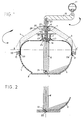
- Figure 1 shows in vertical section along the axis of rotation a preferred embodiment of the entire "salad bowl - brewer" in the on position.
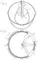
- Figure 2 shows a possible version of the brewer's rotation on the bottom of the bowl.
- Figure 3 shows a perspective view of the bowl and the actual brewer according to the preferred embodiment.
- Figure 4 shows, seen from above, the detail of the locking system of the cover, partially devoid of its superstructure, according to EE ′ in FIG. 1.
- the assembly is characterized by a bowl 1 at the bottom of which turns a brewer 2 actuated by a crank 12.
- a bell 3 ensures hermettim and a cover 4 covering the whole exerts a constant pressure on the brewer by means of a spring 5 when it is in the locking position relative to the bowl.
- the salad bowl can be made of any material (glass, tempered or not, Pyrex, Arcopal, plastic, porcelain, etc.).
- Its internal bottom comprises in its center a projection 7 of frusto-conical shape preferably but which can be cylindrical, conical or both assossées, and on which comes to adapt the axis 6 of the brewer and around which it pivots.
- a variant includes a blind central recess 29 fig. 2, preferably cylindrical, in the thickness of the bottom, in which comes an extension of the axis.
- Patent BE-A-521,140 describes a projection on which the axis of the brewer can adapt and turn “but relates, in fact, to a" salad drainer "using a completely different technique, namely centrifugal force which extracts the water while the "salad bowl - brewer” incorporates ingredients.
- US-A-1,893,628 describes "a central blind recess, in which an extension of the axis of a stirrer can rotate", but this device also uses centrifugal force to essentially knead dough without special precautions while the mixing of the salad requires a lot of delicacy that justifies the special shape of the brewer of the "salad bowl-brewer".
- the actual brewer 2 (see fig. 1 and 3) has the shape of a four-sided volume, preferably made of plastic.
- the base 13 in perfect contact with the bottom of the bowl by the pressure of the lid on the spring of the axis of the brewer, can cover between about 1 / 8th and about half of the base surface of the bowl and preferably 1/4 .
- the second face 14 gradually rises to the wall of the bowl in BC in the form of an inclined plane from the base edge AB at an angle with the base between about 10 ° and about 80 ° and preferably of 18 ° to 20 °.
- the third face 15 whose inclined plane intersects with the face 14 in AC from the base edge AD comes into contact with the wall of the salad bowl in CD and forms with a high vertical plane in AD, an angle of between approximately 10 ° and about 80 ° and preferably about 20 °.
- the fourth face 16 strictly follows the shape of the internal face of the bowl on which it slides and joins the other three faces in CD, BC and BD.
- the lower inner side wall of the bowl has the shape of a small vertical crown 8 of low height serving as a guide for the brewer 2.
- the upper part of this wall has a slight shoulder 9 serving to support the bell 3, before ending vertically.
- the upper edge of the bowl forms outwardly at least two horizontal bosses 10, but preferably four, under which the locking tabs 11 of the cover 4 are placed.
- the stirrer assembly comprises the actual stirrer 2, the axis 6 in the middle part of which the coil spring 5 and the crank 12 are compressed.
- the axis 6 of the stirrer made of metal or plastic, integral with the stirrer itself, and perpendicular to its base, has at its base a recess 31 (see fig. 1) or a projection 32 (see fig. 2) and s 'adapts perfectly respectively to the projection 7 or to the recess 29 depending on the manufacturing method chosen for the bottom of the bowl.
- This cylindrical axis has three parts.
- the first to constant diameter slightly exceeds the bottom of the bell at 18.
- a coil spring 5 which is compressed there between two free washers 17 and 33.
- the third part after a slight shoulder 19 of the second part serves as a guide for the introduction the bell and the cover; it ends tapered and has a flat 20 allowing the positioning of the crank 12 with movable handle 21, directly above the brewer itself.
- the two and three integral parts are screwed or welded at 18 on the first part of the axis.
- the bell 3 convex, made of plastic material, crossed by the axis of the brewer, is positioned on the shoulder 9 of the wall of the bowl by its slightly curved edge 22. Its upper wall is strongly curved at 23 to facilitate its taking and forms a cylindrical void 27 closed at its base 24 by the extension of the internal wall of the bell which is pierced with a hole of diameter very slightly greater than that of the axis of the brewer which it crosses at this point.
- This bell because of the additional volume of stirring that it brings, allows a high quality stirring, eliminates any projection and protects the cover from any stain.
- the plastic cover 4 is a more or less honeycombed volume traversed by the axis at 25 and coming to be positioned above the bell. A pressure exerted vertically on the top and a simultaneous rotation anti-clockwise, block it in a pressure position on the spring and under the bosses of the bowl.
- the axis of the stirrer 6 pivots in contact with its metallic reinforcement 30.
- the circular base of the lid in the shape of an inverted U, is placed astride the edge of the bowl (see fig. 1 and 4).
- the inner side of this U holds the bell at 26.
- the outer side notched enough to be able to be easily placed between the four bosses 10 (see fig. 4), has four solid tabs 11 which lock the cover in the pressure position under the bosses , by reaction of the spring.
- the top and the sides of the cover are grooved 28 in order to facilitate its grip and its maintenance.
- Commissioning consists in positioning the brewer in the salad bowl, putting the salad components in it, positioning the bell, the lid and blocking it, then finally placing the crank.
- a watch generates, among other things, two rotations of the salad, one vertical, the other horizontal, ensuring quality brewing. A few rotations at intervals in the opposite direction are recommended for green salad only.
- the crank is removed, then the cover is released by pressing and turning it to the right and it is removed.
- One hand holds the bell in place through the recess provided, the other hand grabs the pin and pulls it until the brewer touches the bottom of the bell.
- Two or three blows of the brewer against the bell will eliminate the last piece of salad brought back by the brewer. With both hands remaining in this position, the bell and its brewer are quickly turned over and thus transported impeccably for subsequent washing. Everything was done in 10 seconds.
- the invention is of interest to individuals (singles and households) as well as restaurateurs and communities. It is enough to adapt the capacity of the salad bowl to the needs.
Landscapes
- Engineering & Computer Science (AREA)
- Mechanical Engineering (AREA)
- Food Science & Technology (AREA)
- Food-Manufacturing Devices (AREA)
- Seeds, Soups, And Other Foods (AREA)
Claims (8)
- RÜHR- UND SALATGEFÄSS bestehend aus einer Salatschüssel (1) mit einem durch Handgriff (12) in Bewegung setzenden radialen Rührer (2) am Boden und Spritzen sowie Überfliessen beim Mischen der Salate verhindernd. Die Glocke (3) sowie der Deckel (4) garantieren den hermetischen Verschluss. Der Deckel übt mittels einer Feder (5) Druck auf den Rührstab aus, einerseits wenn er bezüglich der salatschüssel blockiert ist und andererseits auch aufgrund der zentralisierenden Stütze in der Mitte des inneren Bodens, die Anpassung und Drehung der radialen Rühreraxe (6) ermöglicht.
- RÜHR- UND SALATGEFÄSS nach Forderung 1 bestimmt durch entweder das Vorhandensein einer Stütze (7) in der Mitte des inneren Bodens der Salatschüssel. Dieser -vorzugsweise kugelstumpfartigen - Erhöhung passt sich die Axe (6) des radialen Rührstabes an und ermöglicht die Drehung. Oder es enthält (nach einem anderen Herstellungsverfahren) die Dicke des Schüsselbodens eine zentrale blinde - vorzugsweise walzenförmige - Aushöhlung (29) zum Drehen der verlängerten Axe (32). In diesem Fall hat der Rührstab die Form eines vierseitigen Volumens, dessen Basis (13) zwischen ca. 1/8 und ca. der Oberflächenhälfte des Schüsselbodens - vorzugsweise 1/4 - bedecken kann. Die zweite Seite (14) steigt allmählich bis zur Schüsselwand BC in Form einer schiefen Ebene ab Basiskante AB gemäss eines Winkels, dessen Basis zwischen ca. 10° und ca. 80° - vorzugsweise 18° - 20° - beträgt. Die dritte Seite (15) deren schiefe Ebene sich mit der Seite (14) in AC zu Beginn der Basiskante AD schneidet, kommt mit der Schüsselwand in CD in Berührung und bildet mit einer erhöhten Vertikalfläche in AD einen Winkel zwischen ca 10° und 80° - vorzugsweise ca. 20° -. Die vierte Seite (16) passt sich genau der Innenseitenform der Salatschüssel an über die sie gleitet und wieder auf die drei anderen Seiten in CD, BC und BD trifft.
- RÜHR- UND SALATGEFÄSS nach den Forderungen 1 und 2 bezeichnend durch das Vorhandensein einer kleinen, vertikalen Krone (8) von geringer Höhe an der niedrigen lateralen Innenwand der Salatschüssel, die der Führung des Rührstabes (2) dient.
- RÜHR- UND SALATGEFÄSS nach den Forderungen 1, 2 und 3 bezeichnend durch eine leichte Ausbuchtung (9) zur Stütze der Glocke (3) am oberen Teil der dann vertikal auslaufenden Innenwand.
- RÜHR- UND SALATGEFÄSS nach den Forderungen 1, 2, 3 und 4 bezeichnend durch das Vorhandensein von mindestens 2 horizontalen - vorzugsweise 4 - Vorsprüngen (10) des oberen Schüsselrandes nach Aussen zur Aufnahme der Blockierungszungen (11) des Deckels (4).
- RÜHR- UND SALATGEFÄSS nach den Forderungen 1 und 2 bezeichnend dadurch, dass die Axe (6) des Rührstabes (2) entweder eine Aushöhlung (31) oder eine Erhöhung (32) aufweist und die Drehungen je nach der gewählten Herstellungsweise des Schüsselbodens in der Aushöhlung (29) oder auf der Erhöhung (7) ermöglicht.
- RÜHR- UND SALATGEFÄSS nach den Forderungen 1 und 4 bezeichnend dadurch, dass sich die Glocke (3) in die Ausbuchtung (9) der Salatschüssel mittels ihres leicht einwärts gekrümmten Randes (22) einfügt. Die obere Wand ist stark einwärts gekrümmt (23) und bildet einen walzenförmigen Leerraum (27) der auf seiner Basis (24) durch die verlängerte innere Glockenwand geschlossen ist. Letztere ist mit einer Lochung versehen, deren Durchmesser etwas über dem der Rührstabsaxe an der Stelle ihres Durchdringens liegt.
- RÜHR- UND SALATGEFÄSS nach den Forderungen 1 und 5 bezeichnend dadurch, dass der Deckel (4) bei der Blockierung durch die Zungen (11) unter den Vorsprüngen (10) mittels einer Schraubenfeder (5) und einem Dichtungsring (33) einen beständigen Druck auf den Rührstab (2) und die Rühruraxe (6) ausübt.
Applications Claiming Priority (2)
| Application Number | Priority Date | Filing Date | Title |
|---|---|---|---|
| FR9001168 | 1990-01-26 | ||
| FR9001168A FR2657517B1 (fr) | 1990-01-26 | 1990-01-26 | Saladier - brasseur. |
Publications (2)
| Publication Number | Publication Date |
|---|---|
| EP0439413A1 EP0439413A1 (de) | 1991-07-31 |
| EP0439413B1 true EP0439413B1 (de) | 1994-07-27 |
Family
ID=9393300
Family Applications (1)
| Application Number | Title | Priority Date | Filing Date |
|---|---|---|---|
| EP91420017A Expired - Lifetime EP0439413B1 (de) | 1990-01-26 | 1991-01-23 | Rühr- und Salatgefäss |
Country Status (4)
| Country | Link |
|---|---|
| EP (1) | EP0439413B1 (de) |
| AT (1) | ATE108990T1 (de) |
| DE (1) | DE69103031T2 (de) |
| FR (1) | FR2657517B1 (de) |
Families Citing this family (5)
| Publication number | Priority date | Publication date | Assignee | Title |
|---|---|---|---|---|
| FR2688131A1 (fr) * | 1992-03-03 | 1993-09-10 | Bonnin Yves | Saladier-brasseur. |
| FR2715287B1 (fr) * | 1994-01-25 | 1996-04-19 | Bruno Mathieu | Appareil pour le brassage de produits en feuilles, notamment du type salade. |
| US6435705B1 (en) * | 1999-04-16 | 2002-08-20 | Depuy Orthopaedics, Inc. | Apparatus and method for delivering and mixing a liquid bone cement component with a powder bone cement component |
| DE202004016636U1 (de) | 2004-07-21 | 2004-12-16 | Moha Moderne Haushaltwaren Ag | Salatschleuder |
| GB201706076D0 (en) | 2017-04-18 | 2017-05-31 | Wecool Toys Inc | Apparatus and a method for the preparation of a play, craft and/or toy compound |
Family Cites Families (5)
| Publication number | Priority date | Publication date | Assignee | Title |
|---|---|---|---|---|
| BE521140A (de) * | ||||
| US1893628A (en) * | 1930-02-21 | 1933-01-10 | John E Marsden | Mixing bowl |
| FR2083717A5 (de) * | 1970-03-12 | 1971-12-17 | Marot Jacques | |
| US3635147A (en) * | 1970-07-23 | 1972-01-18 | Wallace G T Lee | Combination cooking-stirring vessel |
| US4065107A (en) * | 1976-10-29 | 1977-12-27 | Judd Van Horbek | Apparatus for mixing liquids |
-
1990
- 1990-01-26 FR FR9001168A patent/FR2657517B1/fr not_active Expired - Fee Related
-
1991
- 1991-01-23 EP EP91420017A patent/EP0439413B1/de not_active Expired - Lifetime
- 1991-01-23 DE DE69103031T patent/DE69103031T2/de not_active Expired - Fee Related
- 1991-01-23 AT AT91420017T patent/ATE108990T1/de not_active IP Right Cessation
Also Published As
| Publication number | Publication date |
|---|---|
| FR2657517B1 (fr) | 1992-05-07 |
| EP0439413A1 (de) | 1991-07-31 |
| DE69103031D1 (de) | 1994-09-01 |
| FR2657517A1 (fr) | 1991-08-02 |
| ATE108990T1 (de) | 1994-08-15 |
| DE69103031T2 (de) | 1995-04-06 |
Similar Documents
| Publication | Publication Date | Title |
|---|---|---|
| FR2668079A1 (fr) | Godet melangeur pour un malaxeur centrifuge planetaire, et malaxeur recevant de tels godets. | |
| FR2639032A1 (fr) | Recipient comportant un couvercle a liberation de pression | |
| FR2683210A1 (fr) | Assemblage de fermeture pour recipient. | |
| FR2576756A1 (fr) | Recipient de preparation et de stockage de produits alimentaires | |
| FR2986956A1 (fr) | Bol de traitement d'aliments pour un melangeur | |
| EP0439413B1 (de) | Rühr- und Salatgefäss | |
| FR2856892A1 (fr) | Moule souple rigidifie | |
| EP1566124B1 (de) | Verschlussdeckel für ein Behältnis von einem Haushaltsgerät zur Nahrungszubereitung, insbesondere einem Mixer | |
| CH631672A5 (fr) | Recipient avec couvercle, notamment pour la preparation et la conservation d'aliments. | |
| EP0384179B1 (de) | Schleudervorrichtung | |
| FR2559455A1 (fr) | Capuchon de recipient | |
| FR2738897A1 (fr) | Ensemble d'un recipient de stockage de gaz liquefie, comprime ou dissous, sous pression, recipient de stockage de gaz sous pression et chapeau de manutention pour un tel recipient | |
| FR3065633A1 (fr) | Accesoire pour robot menager | |
| EP3708038A1 (de) | Maschine zur herstellung von aufgussgetränken, die mit einem drehbaren filterkorb ausgestattet ist | |
| FR2786384A1 (fr) | Appareil electromenager de preparation culinaire a boitier moteur superieur | |
| BE376464A (de) | ||
| EP3937738B1 (de) | Maschine zur herstellung von brühgetränken mit aufhebbarem filterkorb | |
| EP1419719B1 (de) | Automatischer Deckel für Wasserkocher | |
| EP1733666A1 (de) | Vorrichtung zum Trennen von Eiweiss mit einen Aufnahmebehälter für Eigelb | |
| FR3156441A1 (fr) | Ensemble de traitement de l'eau et appareil de traitement de l’eau comprenant un tel ensemble de traitement | |
| FR3156442A1 (fr) | Ensemble de traitement de l'eau et appareil de traitement de l’eau comprenant un tel ensemble de traitement | |
| FR2688131A1 (fr) | Saladier-brasseur. | |
| FR2636516A1 (fr) | Refouleur d'ebullition | |
| FR3150188A1 (fr) | Diffuseur pour récipient sous pression | |
| WO2016095949A1 (fr) | Verre a boisson |
Legal Events
| Date | Code | Title | Description |
|---|---|---|---|
| PUAI | Public reference made under article 153(3) epc to a published international application that has entered the european phase |
Free format text: ORIGINAL CODE: 0009012 |
|
| AK | Designated contracting states |
Kind code of ref document: A1 Designated state(s): AT BE CH DE ES IT LI NL |
|
| 17P | Request for examination filed |
Effective date: 19920106 |
|
| 17Q | First examination report despatched |
Effective date: 19930408 |
|
| GRAA | (expected) grant |
Free format text: ORIGINAL CODE: 0009210 |
|
| AK | Designated contracting states |
Kind code of ref document: B1 Designated state(s): AT BE CH DE ES IT LI NL |
|
| PG25 | Lapsed in a contracting state [announced via postgrant information from national office to epo] |
Ref country code: IT Free format text: LAPSE BECAUSE OF FAILURE TO SUBMIT A TRANSLATION OF THE DESCRIPTION OR TO PAY THE FEE WITHIN THE PRE;WARNING: LAPSES OF ITALIAN PATENTS WITH EFFECTIVE DATE BEFORE 2007 MAY HAVE OCCURRED AT ANY TIME BEFORE 2007. THE CORRECT EFFECTIVE DATE MAY BE DIFFERENT FROM THE ONE RECORDED.SCRIBED TIME-LIMIT Effective date: 19940727 Ref country code: AT Effective date: 19940727 Ref country code: NL Effective date: 19940727 Ref country code: ES Free format text: THE PATENT HAS BEEN ANNULLED BY A DECISION OF A NATIONAL AUTHORITY Effective date: 19940727 |
|
| REF | Corresponds to: |
Ref document number: 108990 Country of ref document: AT Date of ref document: 19940815 Kind code of ref document: T |
|
| REF | Corresponds to: |
Ref document number: 69103031 Country of ref document: DE Date of ref document: 19940901 |
|
| NLV1 | Nl: lapsed or annulled due to failure to fulfill the requirements of art. 29p and 29m of the patents act | ||
| PLBE | No opposition filed within time limit |
Free format text: ORIGINAL CODE: 0009261 |
|
| STAA | Information on the status of an ep patent application or granted ep patent |
Free format text: STATUS: NO OPPOSITION FILED WITHIN TIME LIMIT |
|
| 26N | No opposition filed | ||
| PGFP | Annual fee paid to national office [announced via postgrant information from national office to epo] |
Ref country code: CH Payment date: 19960206 Year of fee payment: 6 |
|
| PGFP | Annual fee paid to national office [announced via postgrant information from national office to epo] |
Ref country code: BE Payment date: 19960305 Year of fee payment: 6 |
|
| PG25 | Lapsed in a contracting state [announced via postgrant information from national office to epo] |
Ref country code: BE Effective date: 19970131 Ref country code: CH Effective date: 19970131 Ref country code: LI Effective date: 19970131 |
|
| BERE | Be: lapsed |
Owner name: BONNIN PHILIPPE Effective date: 19970131 Owner name: BONNIN YVES Effective date: 19970131 Owner name: BONNIN GEORGETTE Effective date: 19970131 Owner name: BONNIN GERARD Effective date: 19970131 Owner name: BONNIN MARIE-CHRISTINE Effective date: 19970131 Owner name: BONNIN MARIE-CLAUDE Effective date: 19970131 |
|
| REG | Reference to a national code |
Ref country code: CH Ref legal event code: PL |
|
| PGFP | Annual fee paid to national office [announced via postgrant information from national office to epo] |
Ref country code: DE Payment date: 19990713 Year of fee payment: 9 |
|
| PG25 | Lapsed in a contracting state [announced via postgrant information from national office to epo] |
Ref country code: DE Free format text: LAPSE BECAUSE OF NON-PAYMENT OF DUE FEES Effective date: 20001101 |