EP0439237B1 - Méthode et dispositif pour désactiver des étiquettes de détection électromagnétiques - Google Patents
Méthode et dispositif pour désactiver des étiquettes de détection électromagnétiques Download PDFInfo
- Publication number
- EP0439237B1 EP0439237B1 EP91200141A EP91200141A EP0439237B1 EP 0439237 B1 EP0439237 B1 EP 0439237B1 EP 91200141 A EP91200141 A EP 91200141A EP 91200141 A EP91200141 A EP 91200141A EP 0439237 B1 EP0439237 B1 EP 0439237B1
- Authority
- EP
- European Patent Office
- Prior art keywords
- frequency
- label
- detection
- detected
- field
- Prior art date
- Legal status (The legal status is an assumption and is not a legal conclusion. Google has not performed a legal analysis and makes no representation as to the accuracy of the status listed.)
- Expired - Lifetime
Links
Images
Classifications
-
- G—PHYSICS
- G08—SIGNALLING
- G08B—SIGNALLING OR CALLING SYSTEMS; ORDER TELEGRAPHS; ALARM SYSTEMS
- G08B13/00—Burglar, theft or intruder alarms
- G08B13/22—Electrical actuation
- G08B13/24—Electrical actuation by interference with electromagnetic field distribution
- G08B13/2402—Electronic Article Surveillance [EAS], i.e. systems using tags for detecting removal of a tagged item from a secure area, e.g. tags for detecting shoplifting
- G08B13/2405—Electronic Article Surveillance [EAS], i.e. systems using tags for detecting removal of a tagged item from a secure area, e.g. tags for detecting shoplifting characterised by the tag technology used
- G08B13/2414—Electronic Article Surveillance [EAS], i.e. systems using tags for detecting removal of a tagged item from a secure area, e.g. tags for detecting shoplifting characterised by the tag technology used using inductive tags
- G08B13/242—Tag deactivation
-
- G—PHYSICS
- G08—SIGNALLING
- G08B—SIGNALLING OR CALLING SYSTEMS; ORDER TELEGRAPHS; ALARM SYSTEMS
- G08B13/00—Burglar, theft or intruder alarms
- G08B13/22—Electrical actuation
- G08B13/24—Electrical actuation by interference with electromagnetic field distribution
- G08B13/2402—Electronic Article Surveillance [EAS], i.e. systems using tags for detecting removal of a tagged item from a secure area, e.g. tags for detecting shoplifting
- G08B13/2465—Aspects related to the EAS system, e.g. system components other than tags
- G08B13/2488—Timing issues, e.g. synchronising measures to avoid signal collision, with multiple emitters or a single emitter and receiver
Definitions
- This invention relates to a method of deactivating electromagnetic detection labels comprising a resonant circuit, in which an interrogation field is generated, the frequency of which is varied through a frequency range comprising the resonant frequency of the resonant circuit of the detection label, and in which a label is deactivated with an amplified interrogation field.
- the invention further relates to apparatus for deactivating electromagnetic detection labels comprising a resonant circuit, which apparatus comprises a transmitter/receiver with an antenna for generating an interrogation field, and means for generating a field amplified to a deactivating level.
- the invention also relates to an electromagnetic detection system comprising at least one detection zone in which, in operation, by means of one or more transmitters/receivers, an electromagnetic interrogation field can be generated for detecting detection labels comprising a resonant circuit, and a plurality of deactivating devices in which, in operation, detection labels can be detected and deactivated by means of a transmitter/receiver.
- Electromagnetic detection labels can be used in many situations for detecting the presence, and often also the identity, of a person, animal, vehicle, article, etc., in a detection zone.
- An important use for such detection labels is in shop-lifting detection systems.
- each article to be protected is provided with a detection label which comprises a resonant circuit.
- Detection zones are formed near the exits of the shops, where an electromagnetic a.c. field, sometimes referred to as an interrogation field, is generated with the resonant frequency of the electromagnetic labels.
- a sweep field i.e., an interrogation field whose frequency varies periodically at a pre-determined rate between an upper and a lower limit.
- the resonant frequency of the labels is then intermediate these limits.
- the resonant circuit of the label is brought into the resonant state by the electromagnetic field. This fact can be detected either on the basis of the energy absorption caused by it, or on the basis of the secondary field formed by the label proper.
- the labels are normally removed by a shop assistant at the cash desk, as soon as the protected goods have been paid for. In that case the labels do not reach the detection zone. If, however, it is attempted to take the goods outside without paying for them, the labels, which are mostly attached to the goods in a special way, are not removed. Such unremoved labels are detected in the detection zone, whereafter a signal can be given which reminds the customer of his obligation to pay.
- the labels removed by the shop assistant at the cash desk are often designed for re-use. Alternatively, labels are sometimes designed to be used once only. Such labels could be removed at the cash desk, or could simply be deactivated, i.e. modified so that the deactivated labels can be carried through a detection zone without being detected. Deactivation should preferably be effected in a contactless manner, which offers the possibility of attaching the detection labels at a place which is difficult of access. Furthermore, a contactless and preferably also automatic deactivation promotes fast handling at the cash desk.
- Such deactivatable labels can take the form, for example, of stickers.
- deactivatable labels may actually be deactivated, it is necessary for the characteristics of the resonant circuits of the labels to be modified in such a manner that the labels can no longer be detected.
- Known possibilities therefor are, for example, detuning the resonant frequency of the circuit to outside the detection range; changing the quality factor Q of the circuit to a low value; interrupting the circuit, or short-circuiting the circuit.
- detuning the resonant frequency of the circuit to outside the detection range
- changing the quality factor Q of the circuit to a low value
- interrupting the circuit or short-circuiting the circuit.
- Method 1 requires a high voltage to be generated across the capacitor. In method 2, however, a high current must flow through the circuit. In both cases, a much higher electromagnetic field intensity is needed than the field intensity normally used to detect the presence of a label. The maximum energy is transmitted to the resonant frequency of the label.
- Devices to realize this are known by the name of "deactivators".
- a deactivator of the above kind is disclosed in US patent 4,567,473.
- the known deactivator comprises means for generating, in a limited region, an electromagnetic field with a frequency which, to a certain extent, is varied around the resonant frequency of the labels. Furthermore, means are provided in the deactivator to detect the presence of a label in the region, as well as the resonant frequency of the label.
- the operator of the deactivator is subjected to a relatively high biological load with a high-frequency electromagnetic field.
- the prior apparatus has an unnecessarily high power consumption.
- both existing methods often result in spurious radiation as a result of the strong non-synchronized deactivating fields, which may cause interference with interrogation fields generated elsewhere, resulting in false alarm or a reduced chance of detection of the labels.
- a method of the above-described type is characterized in that the frequency of the interrogation field is continuously and periodically varied between a first and a second frequency; that, upon detection of a detection label, the resonant frequency of the label is detected, and that at at least one of the subsequent times the periodically varying frequency passes the detected frequency, the field intensity at the location of the detection label is greatly increased for a short period of time.
- An apparatus for deactivating electromagnetic detection labels of the above kind is characterized, in accordance with the present invention, in that the transmitter/receiver comprises means for generating an interrogation field with a continuously and periodically varying frequency, detection means capable of determining at what value of the varying frequency a label is detected; and means for greatly increasing the field intensity for a short period of time at one or more moments when the said value of the varying frequency is again reached.
- a detection system of the above kind is characterized, in accordance with the present invention, by a central synchronizer coupled with all transmitters/receivers of the detection zones and with the deactivators, and supplies synchronization signals thereto for causing the interrogation/deactivation fields which in operation are generated by said transmitters/receivers to be varied in frequency periodically and continuously and in synchronism.
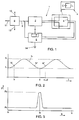
- Fig. 1 shows diagrammatically a deactivator 1 comprising a transmitter/receiver 2 including an antenna 3 by means of which an electromagnetic interrogation field can be generated in a limited region.
- the frequency of the interrogation field is continuously and periodically varied in known manner, for example, by using a VCO (voltage-controlled oscillator) not shown, between a first and a second frequency.
- VCO voltage-controlled oscillator
- This swepped frequency is shown diagrammatically in Fig. 2.
- the frequency f0 of the interrogation field varies periodically and continuously between a lowest frequency f1 and a highest frequency f2.
- the frequency f0 varies sinusoidally, but any other form of gradual variation, for example, according to a triangular or sawtooth form is in principle possible.
- the frequency range f1-f2 comprises the resonant frequency f3 of the resonance circuit LC of the labels used, as the label shown diagrammatically at 4. In other words, the frequency f3 is within
- the resonant circuit LC of the label When a label 4 is within the field formed by antenna 3, the resonant circuit LC of the label is brought into the resonant state when the frequency of the field has the value f3. At that moment, the presence of the label is detected in known manner. Moreover, the resonant frequency of the label is then known, as it corresponds to the instantaneous value of the field frequency.
- the detection of a label can be effected on the basis of the voltage prevailing across antenna 3, which decreases as soon as the resonant circuit of the label is in the resonant state. It is also possible to detect the signal transmitted by the label by means of a separate receiving antenna and a receiver coupled therewith.
- the presence of a label is detected by the transmitter/receiver 2, which upon detecting a label supplies a control signal, for example, a control pulse, to a power end stage 5.
- the power end stage 5 is connected to a separate antenna 6, which in the vicinity of label 4 can generate an amplified field with the resonant frequency of the label in question.
- the amplified field has such a high intensity that the electrical characteristics of the label are modified so as to disable the label.
- the resonant circuit of the label may comprise an easily fusable conductor portion and/or a capacitor which breaks down at an elevated voltage.
- Fig. 2 shows, by way of example, a resonant frequency f3′ of a detected label.
- the label in question has been detected at time t, after the beginning of a periodical frequency sweep.
- the frequency of the detected label is stored in one way or another, either directly or indirectly, and either by digital or analog means.
- the cycles of frequency sweeps are continued without interruptions.
- the intensity of the interrogation field at label 4 is greatly increased.
- control pulse referred to hereinbefore which is supplied by transmitter/receiver 2 to the power end stage 5 upon the detection of a label.
- the power end stage comprises a delay device 7 which in the example shown, after one cycle T of the frequency sweep provides a signal which controls the power end stage in such a manner that the latter energizes antenna 6 with a strong signal.
- Antenna 6 thus forms a strong electromagnetic field at label 4.
- the label is deactivated at time t1 + T.
- the interrogation field is amplified and then attenuated within the bandwidth of the label, which requires no more than a few milliseconds for one burst. If, however, the first burst has not deactivated the label, the label is again detected in a next frequency sweep, and the burst can be generated again.
- Fig. 3 shows diagrammatically the relationship between the sweep width and the power generated.
- the transmitter/receiver 2 of the deactivator remains at the - limited - detection level P0 during the first part of the sweep, and detects a label with a given frequency 3. This frequency is stored. After one or more cycles T, f3 is again passed. During this passage, the field intensity of the interrogation field is suddenly greatly increased until the deactivating level Pd is reached, whereafter the field strength is again attenuated to the detection level.
- the deactivator can continue to be synchronized with other interrogation fields of the (shop-lifting) detection system, as well as with any other components of the detection system which may be provided.
- no spurious signals can occur which normally are the result of the interruption of the frequency sweep or a non-synchronized frequency sweep.
- the burst is limited to the bandwidth of the label, which has a favourable effect on both current consumption and the biological effect of electromagnetic radiation.
- Fig. 1 shows at 8 diagrammatically a central synchronizer which through a plurality of outputs 9-12 supplies synchronization signals to the various detectors and deactivators of a detection system.
- the synchronization signals may consist, for example, of a centrally generated periodic swept-frequency signal which, where necessary, may be provided at the various outputs with suitable phase differences in order to take into account the various distances of the detection and deactivation apparatuses from the central synchronizer.
- devices 2 and 5 may be integrated to form one single apparatus, and also it would be possible to use one single antenna for both detecting a label and deactivating a label.
- the delay device may be an analog delay line but, alternatively may be a digital delay device comprising, for example, a counter or a shift register, as well as a suitable clock pulse generator which preferably is phase-locked with the swept frequency.
- the deactivator may be arranged so that the field intensity is not increased until after the presence of the label has been detected a pre-determined minimum number of times.
- a label detected during the rising part of a frequency sweep may already be deactivated during the next descending part of the sweep,.as shown in Fig. 2 at f3 ⁇ .
- means as shown at 14 in Fig. 1 may be provided for manually switching on the amplified field in case a label cannot be deactivated in the normal manner.
Landscapes
- Physics & Mathematics (AREA)
- Engineering & Computer Science (AREA)
- Automation & Control Theory (AREA)
- Computer Security & Cryptography (AREA)
- Electromagnetism (AREA)
- General Physics & Mathematics (AREA)
- Geophysics And Detection Of Objects (AREA)
- Burglar Alarm Systems (AREA)
- Measurement Of Length, Angles, Or The Like Using Electric Or Magnetic Means (AREA)
- Radar Systems Or Details Thereof (AREA)
Claims (12)
- Procédé pour désactiver des étiquettes de détection électromagnétiques comprenant un circuit résonnant, dans lequel un champ d'interrogation est produit, dont la fréquence varie sur une plage de fréquence incluant la fréquence de résonance du circuit résonnant de l'étiquette de détection et dans lequel une étiquette est désactivée par un champ d'interrogation amplifié, caractérisé en ce que la fréquence du champ d'interrogation varie continuellement et périodiquement entre des première et seconde fréquences, en ce que sur détection d'une étiquette de détection, la fréquence de résonance de l'étiquette est détectée et en ce qu'au moins à l'un des instants ultérieurs où la fréquence variant périodiquement passe par la fréquence détectée, l'intensité du champ à l'emplacement de l'étiquette de détection est largement accrue pendant un court intervalle de temps.
- Procédé selon la revendication 1, caractérisé en ce que l'intensité accrue du champ est produite à un ou plusieurs instants à un ou plusieurs cycles de variation de fréquence après l'instant où l'étiquette a été détectée.
- Procédé selon la revendication 2, caractérisé en ce que les instants où l'intensité du champ est accrue sont déterminés au moyen d'un dispositif à retard.
- Procédé selon l'une quelconque des revendications précédentes, caractérisé en ce que l'intensité du champ n'est pas accrue tant que l'étiquette n'a pas été détectée pendant un nombre minimal prédéterminé de cycles de variation de fréquence.
- Procédé selon l'une quelconque des revendications précédentes, caractérisé par l'étape consistant à vérifier si une étiquette détectable avec le champ d'interrogation est présente après que l'intensité du champ ait été grandement accrue une ou plusieurs fois et augmenter l'intensité du champ une ou plusieurs fois à la fréquence de résonance de l'étiquette lorsqu'une étiquette détectable est présente.
- Système de détection électromagnétique comprenant au moins une zone de détection dans laquelle, en fonctionnement, au moyen d'un ou plusieurs émetteurs/récepteurs, un champ d'interrogation électromagnétique peut être produit pour détecter des étiquettes de détection comprenant un circuit résonnant, et une pluralité de dispositifs de désactivation dans lesquels, en fonctionnement, les étiquettes de détection peuvent être détectées et désactivées au moyen d'un émetteur/récepteur, caractérisé en ce que l'émetteur/récepteur comprend un moyen pour produire un champ d'interrogation avec une fréquence qui varie continuellement et périodiquement, un moyen de détection capable de déterminer pour quelle valeur de l'excursion en fréquence l'étiquette est détectée, et un moyen pour accroître largement l'intensité du champ pendant un court intervalle de temps à un ou plusieurs instants lorsque ladite valeur de ladite excursion en fréquence est de nouveau atteinte.
- Dispositif selon la revendication 6, caractérisé en ce que le moyen pour accroître l'intensité du champ comprend un étage final de puissance et un dispositif à retard activant l'étage final de puissance à un instant prédéterminé après qu'une étiquette ait été détectée.
- Dispositif selon la revendication 7, caractérisé en ce que ledit dispositif à retard est un dispositif à retard numérique.
- Dispositif selon la revendication 7 ou 8, caractérisé en ce que ledit temps prédéterminé est égal à un cycle (T) de l'excursion en fréquence.
- Dispositif selon la revendication 7 , 8 ou 9, caractérisé en ce que l'étage final de puissance est relié à une antenne séparée.
- Dispositif selon l'une quelconque des revendications 7 à 10, caractérisé en ce que l'étage final de puissance comporte un moyen pour être activé manuellement.
- Système de détection électromagnétique comprenant au moins une zone de détection dans laquelle, en fonctionnement, au moyen d'un ou plusieurs émetteurs/récepteurs, un champ d'interrogation électromagnétique peut être produit pour détecter des étiquettes de détection comprenant un circuit résonnant, et une pluralité de dispositifs de désactivation dans lesquels, en fonctionnement, les étiquettes de détection peuvent être détectées et désactivées au moyen d'un émetteur/récepteur, caractérisé par un synchronisateur central couplé à la totalité des émetteurs/récepteurs des zones de détection et aux désactivateurs, et délivrant des signaux de synchronisation à ceux-ci pour amener les champs d'interrogation/désactivation qui, en fonctionnement, sont produits par lesdits émetteurs/récepteurs à varier en fréquence périodiquement et continuellement et en synchronisme.
Applications Claiming Priority (2)
| Application Number | Priority Date | Filing Date | Title |
|---|---|---|---|
| NL9000186 | 1990-01-25 | ||
| NL9000186A NL9000186A (nl) | 1990-01-25 | 1990-01-25 | Deactiveerinrichting. |
Publications (2)
| Publication Number | Publication Date |
|---|---|
| EP0439237A1 EP0439237A1 (fr) | 1991-07-31 |
| EP0439237B1 true EP0439237B1 (fr) | 1995-01-04 |
Family
ID=19856479
Family Applications (1)
| Application Number | Title | Priority Date | Filing Date |
|---|---|---|---|
| EP91200141A Expired - Lifetime EP0439237B1 (fr) | 1990-01-25 | 1991-01-24 | Méthode et dispositif pour désactiver des étiquettes de détection électromagnétiques |
Country Status (7)
| Country | Link |
|---|---|
| US (1) | US5153562A (fr) |
| EP (1) | EP0439237B1 (fr) |
| AT (1) | ATE116756T1 (fr) |
| DE (1) | DE69106395T2 (fr) |
| DK (1) | DK0439237T3 (fr) |
| ES (1) | ES2069188T3 (fr) |
| NL (1) | NL9000186A (fr) |
Families Citing this family (14)
| Publication number | Priority date | Publication date | Assignee | Title |
|---|---|---|---|---|
| NL9002120A (nl) * | 1990-09-28 | 1992-04-16 | Nedap Nv | Pulsdeactivator. |
| US5337040A (en) * | 1991-10-31 | 1994-08-09 | Actron Entwicklungs Ag | Detection apparatus for shoplifting-preventing labels |
| DK167829B1 (da) * | 1991-11-14 | 1993-12-20 | Poul Richter Joergensen | Fremgangsmaade og apparat til aktivering og deaktivering af maerkesedler |
| US5288980A (en) * | 1992-06-25 | 1994-02-22 | Kingsley Library Equipment Company | Library check out/check in system |
| US7123129B1 (en) * | 1995-08-14 | 2006-10-17 | Intermec Ip Corp. | Modulation of the resonant frequency of a circuit using an energy field |
| FI100491B (fi) * | 1995-08-23 | 1997-12-15 | Tuotesuoja Sirpa Jaervensivu K | Tuotesuoja-anturin deaktivointilaitteisto |
| US6232878B1 (en) * | 1999-05-20 | 2001-05-15 | Checkpoint Systems, Inc. | Resonant circuit detection, measurement and deactivation system employing a numerically controlled oscillator |
| US6963270B1 (en) | 1999-10-27 | 2005-11-08 | Checkpoint Systems, Inc. | Anticollision protocol with fast read request and additional schemes for reading multiple transponders in an RFID system |
| ES2324639T3 (es) * | 2000-11-16 | 2009-08-12 | Checkpoint Systems, Inc. | Metodo de lectura de transpondedores multiples en un sistema rfid. |
| US8508367B2 (en) | 2009-09-21 | 2013-08-13 | Checkpoint Systems, Inc. | Configurable monitoring device |
| US8452868B2 (en) | 2009-09-21 | 2013-05-28 | Checkpoint Systems, Inc. | Retail product tracking system, method, and apparatus |
| EP3450201B1 (fr) * | 2017-09-04 | 2020-07-01 | Continental Reifen Deutschland GmbH | Procédé de fabrication d'un mélange de caoutchouc et mélange de caoutchouc fabriqué selon le procédé |
| US10511347B2 (en) * | 2017-11-14 | 2019-12-17 | Nxp B.V. | Device detection in contactless communication systems |
| CN112037452B (zh) * | 2020-09-10 | 2023-02-21 | 成都威图芯晟科技有限公司 | 电子商品防盗系统、发射机及防盗信号生成方法 |
Family Cites Families (7)
| Publication number | Priority date | Publication date | Assignee | Title |
|---|---|---|---|---|
| US3810147A (en) * | 1971-12-30 | 1974-05-07 | G Lichtblau | Electronic security system |
| US4498076A (en) * | 1982-05-10 | 1985-02-05 | Lichtblau G J | Resonant tag and deactivator for use in an electronic security system |
| US4728938A (en) * | 1986-01-10 | 1988-03-01 | Checkpoint Systems, Inc. | Security tag deactivation system |
| US4876555B1 (en) * | 1987-03-17 | 1995-07-25 | Actron Entwicklungs Ag | Resonance label and method for its fabrication |
| ES2039005T3 (es) * | 1987-04-23 | 1993-08-16 | Actron Entwicklungs Ag | Procedimiento para la desactivacion de una etiqueta de resonancia y disposicion de circuito para la realizacion del procedimiento. |
| US4920335A (en) * | 1989-01-31 | 1990-04-24 | Interamerican Industrial Company | Electronic article surveillance device with remote deactivation |
| US5012225A (en) * | 1989-12-15 | 1991-04-30 | Checkpoint Systems, Inc. | System for deactivating a field-sensitive tag or label |
-
1990
- 1990-01-25 NL NL9000186A patent/NL9000186A/nl not_active Application Discontinuation
-
1991
- 1991-01-24 EP EP91200141A patent/EP0439237B1/fr not_active Expired - Lifetime
- 1991-01-24 AT AT91200141T patent/ATE116756T1/de not_active IP Right Cessation
- 1991-01-24 DE DE69106395T patent/DE69106395T2/de not_active Expired - Lifetime
- 1991-01-24 DK DK91200141.9T patent/DK0439237T3/da active
- 1991-01-24 ES ES91200141T patent/ES2069188T3/es not_active Expired - Lifetime
- 1991-01-25 US US07/645,886 patent/US5153562A/en not_active Expired - Lifetime
Also Published As
| Publication number | Publication date |
|---|---|
| EP0439237A1 (fr) | 1991-07-31 |
| NL9000186A (nl) | 1991-08-16 |
| DK0439237T3 (da) | 1995-06-12 |
| US5153562A (en) | 1992-10-06 |
| ES2069188T3 (es) | 1995-05-01 |
| ATE116756T1 (de) | 1995-01-15 |
| DE69106395D1 (de) | 1995-02-16 |
| DE69106395T2 (de) | 1995-05-04 |
Similar Documents
| Publication | Publication Date | Title |
|---|---|---|
| EP0439237B1 (fr) | Méthode et dispositif pour désactiver des étiquettes de détection électromagnétiques | |
| US4356477A (en) | FM/AM Electronic security system | |
| EP0181327B2 (fr) | Etiquette resonante et desactivateur utilises dans un systeme de securite electronique | |
| EP1181677B1 (fr) | Systeme de detection, mesure et desactivation d'un circuit resonnant, mettant en oeuvre un oscillateur a commande numerique | |
| US3863244A (en) | Electronic security system having improved noise discrimination | |
| EP0131440B1 (fr) | TSF-système électronique de surveillance avec fréquence variable | |
| US4303910A (en) | Detection system | |
| CA1145015A (fr) | Systemes de surveillance | |
| US5027106A (en) | Method and apparatus for electronic article surveillance | |
| JP2003533143A (ja) | 無線周波数検出識別システム | |
| US6034604A (en) | Deactivation prevention for electronic article surveillance systems | |
| RU2138855C1 (ru) | Элемент сигнализации | |
| EP0516666B1 (fr) | Systeme de securite surveillant le passage de marchandises a travers des zones definies | |
| AU584306B2 (en) | Electronically detectable and deactivatable security tag | |
| WO1997008670A1 (fr) | Dispositif de desactivation pour etiquette de controle d'article | |
| GB1604220A (en) | Detection systems | |
| EP0226239A1 (fr) | Système de détection électromagnétique à sensibilité élevée | |
| JPS6336465Y2 (fr) | ||
| AU2004201196A1 (en) | Resonant Circuit Detection, Measurement and Deactivation System Employing a Numerically Controlled Oscillator |
Legal Events
| Date | Code | Title | Description |
|---|---|---|---|
| PUAI | Public reference made under article 153(3) epc to a published international application that has entered the european phase |
Free format text: ORIGINAL CODE: 0009012 |
|
| AK | Designated contracting states |
Kind code of ref document: A1 Designated state(s): AT BE CH DE DK ES FR GB IT LI LU NL SE |
|
| 17P | Request for examination filed |
Effective date: 19910620 |
|
| 17Q | First examination report despatched |
Effective date: 19940304 |
|
| GRAA | (expected) grant |
Free format text: ORIGINAL CODE: 0009210 |
|
| PGFP | Annual fee paid to national office [announced via postgrant information from national office to epo] |
Ref country code: LU Payment date: 19950101 Year of fee payment: 5 |
|
| AK | Designated contracting states |
Kind code of ref document: B1 Designated state(s): AT BE CH DE DK ES FR GB IT LI LU NL SE |
|
| REF | Corresponds to: |
Ref document number: 116756 Country of ref document: AT Date of ref document: 19950115 Kind code of ref document: T |
|
| PGFP | Annual fee paid to national office [announced via postgrant information from national office to epo] |
Ref country code: SE Payment date: 19950116 Year of fee payment: 5 |
|
| PGFP | Annual fee paid to national office [announced via postgrant information from national office to epo] |
Ref country code: DK Payment date: 19950117 Year of fee payment: 5 |
|
| ITF | It: translation for a ep patent filed |
Owner name: MARCHI & MITTLER S.R.L. |
|
| PGFP | Annual fee paid to national office [announced via postgrant information from national office to epo] |
Ref country code: AT Payment date: 19950126 Year of fee payment: 5 |
|
| PGFP | Annual fee paid to national office [announced via postgrant information from national office to epo] |
Ref country code: BE Payment date: 19950127 Year of fee payment: 5 |
|
| PGFP | Annual fee paid to national office [announced via postgrant information from national office to epo] |
Ref country code: ES Payment date: 19950131 Year of fee payment: 5 |
|
| REF | Corresponds to: |
Ref document number: 69106395 Country of ref document: DE Date of ref document: 19950216 |
|
| PGFP | Annual fee paid to national office [announced via postgrant information from national office to epo] |
Ref country code: CH Payment date: 19950428 Year of fee payment: 5 |
|
| REG | Reference to a national code |
Ref country code: ES Ref legal event code: FG2A Ref document number: 2069188 Country of ref document: ES Kind code of ref document: T3 |
|
| ET | Fr: translation filed | ||
| REG | Reference to a national code |
Ref country code: DK Ref legal event code: T3 |
|
| PLBE | No opposition filed within time limit |
Free format text: ORIGINAL CODE: 0009261 |
|
| STAA | Information on the status of an ep patent application or granted ep patent |
Free format text: STATUS: NO OPPOSITION FILED WITHIN TIME LIMIT |
|
| 26N | No opposition filed | ||
| PG25 | Lapsed in a contracting state [announced via postgrant information from national office to epo] |
Ref country code: AT Effective date: 19960124 Ref country code: DK Effective date: 19960124 Ref country code: LU Free format text: LAPSE BECAUSE OF NON-PAYMENT OF DUE FEES Effective date: 19960124 |
|
| REG | Reference to a national code |
Ref country code: DK Ref legal event code: EBP |
|
| PG25 | Lapsed in a contracting state [announced via postgrant information from national office to epo] |
Ref country code: SE Effective date: 19960125 Ref country code: ES Free format text: LAPSE BECAUSE OF NON-PAYMENT OF DUE FEES Effective date: 19960125 |
|
| PG25 | Lapsed in a contracting state [announced via postgrant information from national office to epo] |
Ref country code: LI Effective date: 19960131 Ref country code: BE Effective date: 19960131 Ref country code: CH Effective date: 19960131 |
|
| BERE | Be: lapsed |
Owner name: NEDERLANDSCHE APPARATENFABRIEK NEDAP N.V. Effective date: 19960131 |
|
| REG | Reference to a national code |
Ref country code: CH Ref legal event code: PL |
|
| EUG | Se: european patent has lapsed |
Ref document number: 91200141.9 |
|
| REG | Reference to a national code |
Ref country code: ES Ref legal event code: FD2A Effective date: 19990503 |
|
| REG | Reference to a national code |
Ref country code: GB Ref legal event code: IF02 |
|
| PG25 | Lapsed in a contracting state [announced via postgrant information from national office to epo] |
Ref country code: IT Free format text: LAPSE BECAUSE OF NON-PAYMENT OF DUE FEES;WARNING: LAPSES OF ITALIAN PATENTS WITH EFFECTIVE DATE BEFORE 2007 MAY HAVE OCCURRED AT ANY TIME BEFORE 2007. THE CORRECT EFFECTIVE DATE MAY BE DIFFERENT FROM THE ONE RECORDED. Effective date: 20050124 |
|
| PGFP | Annual fee paid to national office [announced via postgrant information from national office to epo] |
Ref country code: FR Payment date: 20100223 Year of fee payment: 20 |
|
| PGFP | Annual fee paid to national office [announced via postgrant information from national office to epo] |
Ref country code: DE Payment date: 20100121 Year of fee payment: 20 Ref country code: GB Payment date: 20100121 Year of fee payment: 20 |
|
| PGFP | Annual fee paid to national office [announced via postgrant information from national office to epo] |
Ref country code: NL Payment date: 20100118 Year of fee payment: 20 |
|
| REG | Reference to a national code |
Ref country code: NL Ref legal event code: V4 Effective date: 20110124 |
|
| REG | Reference to a national code |
Ref country code: GB Ref legal event code: PE20 Expiry date: 20110123 |
|
| PG25 | Lapsed in a contracting state [announced via postgrant information from national office to epo] |
Ref country code: NL Free format text: LAPSE BECAUSE OF EXPIRATION OF PROTECTION Effective date: 20110124 |
|
| PG25 | Lapsed in a contracting state [announced via postgrant information from national office to epo] |
Ref country code: GB Free format text: LAPSE BECAUSE OF EXPIRATION OF PROTECTION Effective date: 20110123 |
|
| PG25 | Lapsed in a contracting state [announced via postgrant information from national office to epo] |
Ref country code: DE Free format text: LAPSE BECAUSE OF EXPIRATION OF PROTECTION Effective date: 20110124 |