EP0438898B1 - Reusable mechanical connector for optical fibers - Google Patents
Reusable mechanical connector for optical fibers Download PDFInfo
- Publication number
- EP0438898B1 EP0438898B1 EP90313869A EP90313869A EP0438898B1 EP 0438898 B1 EP0438898 B1 EP 0438898B1 EP 90313869 A EP90313869 A EP 90313869A EP 90313869 A EP90313869 A EP 90313869A EP 0438898 B1 EP0438898 B1 EP 0438898B1
- Authority
- EP
- European Patent Office
- Prior art keywords
- optical fiber
- connector
- mount
- groove
- block
- Prior art date
- Legal status (The legal status is an assumption and is not a legal conclusion. Google has not performed a legal analysis and makes no representation as to the accuracy of the status listed.)
- Expired - Lifetime
Links
Images

Classifications
-
- G—PHYSICS
- G02—OPTICS
- G02B—OPTICAL ELEMENTS, SYSTEMS OR APPARATUS
- G02B6/00—Light guides; Structural details of arrangements comprising light guides and other optical elements, e.g. couplings
- G02B6/24—Coupling light guides
-
- G—PHYSICS
- G02—OPTICS
- G02B—OPTICAL ELEMENTS, SYSTEMS OR APPARATUS
- G02B6/00—Light guides; Structural details of arrangements comprising light guides and other optical elements, e.g. couplings
- G02B6/24—Coupling light guides
- G02B6/42—Coupling light guides with opto-electronic elements
- G02B6/4292—Coupling light guides with opto-electronic elements the light guide being disconnectable from the opto-electronic element, e.g. mutually self aligning arrangements
-
- G—PHYSICS
- G02—OPTICS
- G02B—OPTICAL ELEMENTS, SYSTEMS OR APPARATUS
- G02B6/00—Light guides; Structural details of arrangements comprising light guides and other optical elements, e.g. couplings
- G02B6/24—Coupling light guides
- G02B6/36—Mechanical coupling means
- G02B6/38—Mechanical coupling means having fibre to fibre mating means
- G02B6/3801—Permanent connections, i.e. wherein fibres are kept aligned by mechanical means
- G02B6/3806—Semi-permanent connections, i.e. wherein the mechanical means keeping the fibres aligned allow for removal of the fibres
-
- G—PHYSICS
- G02—OPTICS
- G02B—OPTICAL ELEMENTS, SYSTEMS OR APPARATUS
- G02B6/00—Light guides; Structural details of arrangements comprising light guides and other optical elements, e.g. couplings
- G02B6/24—Coupling light guides
- G02B6/36—Mechanical coupling means
- G02B6/38—Mechanical coupling means having fibre to fibre mating means
- G02B6/3801—Permanent connections, i.e. wherein fibres are kept aligned by mechanical means
- G02B6/3803—Adjustment or alignment devices for alignment prior to splicing
-
- G—PHYSICS
- G02—OPTICS
- G02B—OPTICAL ELEMENTS, SYSTEMS OR APPARATUS
- G02B6/00—Light guides; Structural details of arrangements comprising light guides and other optical elements, e.g. couplings
- G02B6/24—Coupling light guides
- G02B6/36—Mechanical coupling means
- G02B6/38—Mechanical coupling means having fibre to fibre mating means
- G02B6/3807—Dismountable connectors, i.e. comprising plugs
- G02B6/3833—Details of mounting fibres in ferrules; Assembly methods; Manufacture
- G02B6/3834—Means for centering or aligning the light guide within the ferrule
- G02B6/3838—Means for centering or aligning the light guide within the ferrule using grooves for light guides
Definitions
- the invention concerns optical fiber connectors such as can coaxially interconnect two optical fibers or can connect an optical fiber to an opto-electronic element.
- the invention is particularly concerned with connecting polarizing or polarization-maintaining optical fibers.
- Prior optical fiber connectors tend to be expensive, often requiring mechanical elements to be secured permanently to the optical fibers, followed by attaching each such element either to a complementary element or to a fixture. Doing so can require special tools.
- a relatively inexpensive optical fiber connector can be constructed as disclosed in U.S. Pat. No. 4,470,180 (Blomgren).
- a preferred Blomgren connector includes an elongated mount of substantially uniformly elliptical cross section that is encompassed by a resiliently deformable housing which, in its relatively undeformed state, can pinch a free end of an optical fiber against at least one straight longitudinal groove in the surface of the mount. Upon squeezing to deform the housing, a free end of a second optical fiber can be inserted to become coaxially interconnected with the first as shown in Blomgren Fig. 6C.
- An optical fiber connector now on the market (“Dorran” mechanical splice from 3M) is constructed as taught in the Blomgren patent and further has a strain-relief chock which grips a buffer layer that protects the optical fiber except at its free end which is bare.
- the buffer is in turn covered by a jacket and an intermediate layer of "Kevlar” fibers which can be stripped back to expose the buffer.
- a reusable mechanical connector for an optical fiber which connector comprises (a) an elongated mount, the surface of which is formed with at least one straight longitudinal groove and (b) a deformable housing surrounding said mount, which housing when undeformed is substantially cylindrical and can pinch a respective bare end of an optical fiber against the groove, said connector being characterized in that:- said connector is adapted for use with an optical fiber having a protective buffer; said groove has a uniformly relatively shallow portion for a bare end of the optical fiber; and said groove has a uniformly relatively deep portion for an adjacent portion of the optical fiber buffer, such that the outermost surfaces of the optical fiber bare end and buffer define a substantially straight line, thus permitting said deformable housing to pinch the optical fiber and buffer against the mount simultaneously.
- the novel connector is inexpensive to construct and includes (a) an elongated mount, the surface of which is formed with at least one straight longitudinal groove, and (b) a deformable housing surrounding said mount, which housing when undeformed is substantially cylindrical and can pinch a bare end of an optical fiber against the groove.
- the elongated mount of the Blomgren patent that of the invention preferably has a substantially uniform elliptical cross section.
- the novel optical fiber connector differs from that of the Blomgren patent in that the groove in the mount has uniformly shallow and uniformly deep portions that respectively receive both a bare end of an optical fiber and the adjacent portion of its buffer such that the outermost surfaces of the bare end and buffer lie in a substantially straight line. This permits the deformable housing to pinch the optical fiber and buffer against the mount simultaneously.
- bare end is meant the portion of the optical fiber from which the buffer is stripped off, e.g., a core-cladding.
- a non-strippable protective layer beneath the buffer, that protective layer is part of the bare end.
- optical fibers may be more quickly and easily assembled into the novel connector, because both the bare end of the optical fiber and its buffer can be secured in a single motion.
- the groove formed in the mount has a central shallow portion and outer deep portions, and said deformable housing can pinch simultaneously the bare ends of both fibers and their buffers when the bare ends abut at the shallow portion of the groove.
- the novel connector is particularly useful for interconnecting polarizing or polarization-maintaining optical fibers, because the connection can be tested, readjusted by fiber rotation, and retested until the desired transmission is attained.
- the mount of the novel connector can be a single piece that preferably is a block of ceramic, because (1) ceramic can closely match the mechanical and thermal properties of glass, the material of which most optical fibers are made, and (2) a ceramic block can be produced with precision geometry and surfaces. Other materials that have similar characteristics include certain metal alloys and a liquid crystal polymer such is available as "Xydar" from Amoco Performance Products.
- the buffer-supporting mount portions (here called "chocks") can be formed less expensively, e.g., from synthetic resin.
- a preferred synthetic resin is polycarbonate which is a tough, dimensionally stable, and substantially chemically inert thermoplastic resin.
- the groove of a connector of the invention can have its deep portions formed to permit the outermost portions of mismatched buffers to define a substantially straight line.
- the central shallow portion of a groove of a novel connector can likewise have two different depths to permit the interconnection of optical fibers having bare ends of differing sizes.
- the novel optical fiber connector is reusable, it can be employed in a manner that prevents it from being reused.
- a curable resin can be used to bond the bare fiber ends together permanently. Doing so could provide a hermetic seal and also enhance resistance to pull-out.
- the cured resin has a refractive index matching that of the optical fibers, it can enhance the transmission of light across the interconnection.
- Detuning can also be accomplished in the novel connector by maintaining a desired spacing between the interconnected fibers or by forming the longitudinal groove in the mount to have a central discontinuity to position the abutting optical fibers slightly out of perfect coaxial alignment.
- the mount can be quickly and inexpensively changed from time to time to reduce the attenuation, thus keeping the transmitted signal levels substantially constant.
- FIG. 2 shows an optical fiber connector of the invention that can interconnect two optical fibers, except that the connector of FIG. 2 connects an optical fiber to an opto-electronic element. Some of the illustrated connectors are partly broken away to reveal details.
- the optical fiber connector 10 of FIG. 1 has an elongated mount consisting of a ceramic block 11 of substantially uniform cross section that approximates an ellipse, and its surface is formed with a straight longitudinal V-groove 13 extending the full length of the block at a major axis of the ellipse.
- the longitudinal groove has a uniformly shallow central portion in which the bare ends 14 and 14A of a pair of optical fibers can nest and uniformly deeper outer portions in which the adjacent buffers 16 and 16A can nest such that the outermost surfaces of both the nested bare ends and the buffers define a substantially straight line that lies in the plane defined by the major axis of the elliptical mount.
- a deformable housing 18 Surrounding the ceramic block is a deformable housing 18 which is substantially cylindrical when not deformed.
- the housing 18 When the housing 18 is squeezed in the direction of the minor axis of the block 11, the optical fibers can be freely inserted or removed.
- the groove 13 opens into a bell mouth 19, 19A to enhance threading optical fibers into the groove.
- the housing After the optical fibers abut, the housing is released to return to its substantially cylindrical state to pinch each of the bare ends 14 and 14A and the buffers 16 and 16A against the longitudinal groove 13.
- the deformable housing 18 is sufficiently transparent to permit one to see that each of the bare ends 14 and 14A extends approximately to the center of the connector 10. When one of the optical fibers is inserted to reach the center of the connector, it acts as a stop for the other optical fiber.
- an optical fiber connector 20 which is identical in construction to half of the optical fiber connector 10 of FIG. 1, permits a single optical fiber 25 to be connected to an opto-electronic element 27 while being pinched by a deformable housing 28.
- the optical fiber connector 30 of FIG. 3 has an elongated mount consisting of a central ceramic block 31 and a pair of plastic chocks 32 and 32A, which mount has a substantially uniform cross section that approximates an ellipse. Formed at the major axis of the elliptical mount is a straight longitudinal V-groove 33 that extends in a straight line over the length of the mount, because the block and chocks are (a) formed to interlock against relative rotation, (b) maintained in alignment by a deformable housing 38, and (c) releasably interlocked by detent means formed in the block and chocks at 37.
- That portion of the groove 33 that is formed in the block 31 is uniformly shallow, and the portions that are formed in the chocks 32 and 32A are uniformly deep up to bell mouths 39 and 39A, respectively, at the extremities of the mount.
- the outermost surfaces of both the nested bare fiber ends 34 and 34A and buffers 36 and 36A lie in a substantially straight line.
- the length of the housing 38 approximates the length of the mount, it could be shorter for various reasons, e.g., to make it easy to grasp the ends of the chocks 32 and 32A for removal or to permit the ends of the chocks to fit into connector-mounting means (not shown).
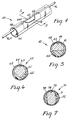
- the optical fiber connector 40 of FIGS. 4 and 5 has an elongated mount consisting of a central ceramic block 41 which nests in a saddle chock 42. When so nested, the block 41 and chock 42 have a substantially uniform cross section that approximates an ellipse. Formed at the major axis of the elliptical mount is a straight longitudinal V-groove 43.
- the block is held in the illustrated position by a deformable housing 48 that pinches the bare ends 44 and 44A and buffers 46 and 46A of a pair of optical fibers in the same manner as in FIG. 3.
- the optical fiber connector 60 of FIG. 6 has an elongated mount consisting of a central ceramic block 61 which nests in a saddle chock 62 in a manner similar to the connector 40 of FIGS. 4 and 5. Extending the length of the assembled block 61 and chock 62 is a straight longitudinal V-groove 63. The block is held in the illustrated position by a deformable housing 68 which normally pinches the bare ends (one shown at 64) and buffers (not shown) of a pair of optical fibers.
- the optical fiber connector 70 of FIG. 7 has an elongated mount consisting of a central ceramic block 71 which nests in a saddle chock 72 and is held there by a deformable housing 78.
- the assembled block and chock together have a straight longitudinal V-groove 73.
- a bare end 74 of an optical fiber is shown being pinched by the deformable housing 78.
- a prototype of the connector 30 illustrated in FIG. 3 has been constructed to splice a pair of optical fibers, each having a glass core-cladding 125 ⁇ m in diameter and a buffer 250 ⁇ m in diameter.
- the block 31 was ceramic, and the chocks 32 were polycarbonate.
- Key dimensions of the prototype were: The heights were measured with a micrometer. The difference in the heights of the bare end and buffer above the V-groove is due in part to the greater breadth of the V-groove where it receives the buffer.
- the buffer is resilient and hence slightly compressed by the housing, and because of this, pull-out resistance is enhanced.
Landscapes
- Physics & Mathematics (AREA)
- General Physics & Mathematics (AREA)
- Optics & Photonics (AREA)
- Mechanical Coupling Of Light Guides (AREA)
Applications Claiming Priority (2)
| Application Number | Priority Date | Filing Date | Title |
|---|---|---|---|
| US46117690A | 1990-01-05 | 1990-01-05 | |
| US461176 | 1990-01-05 |
Publications (2)
| Publication Number | Publication Date |
|---|---|
| EP0438898A1 EP0438898A1 (en) | 1991-07-31 |
| EP0438898B1 true EP0438898B1 (en) | 1994-08-03 |
Family
ID=23831504
Family Applications (1)
| Application Number | Title | Priority Date | Filing Date |
|---|---|---|---|
| EP90313869A Expired - Lifetime EP0438898B1 (en) | 1990-01-05 | 1990-12-19 | Reusable mechanical connector for optical fibers |
Country Status (24)
| Country | Link |
|---|---|
| EP (1) | EP0438898B1 (pl) |
| JP (1) | JPH04218005A (pl) |
| KR (1) | KR910014725A (pl) |
| CN (1) | CN1027013C (pl) |
| AR (1) | AR245990A1 (pl) |
| AT (1) | ATE109572T1 (pl) |
| AU (1) | AU648284B2 (pl) |
| BR (1) | BR9006667A (pl) |
| CA (1) | CA2032353A1 (pl) |
| CZ (1) | CZ282418B6 (pl) |
| DE (1) | DE69011311T2 (pl) |
| DK (1) | DK0438898T3 (pl) |
| ES (1) | ES2057451T3 (pl) |
| FI (1) | FI906176L (pl) |
| HK (1) | HK6597A (pl) |
| HU (1) | HU213333B (pl) |
| IE (1) | IE904571A1 (pl) |
| IL (1) | IL96727A (pl) |
| MX (1) | MX172759B (pl) |
| NO (1) | NO905640L (pl) |
| PL (1) | PL165097B1 (pl) |
| TR (1) | TR26397A (pl) |
| YU (1) | YU246490A (pl) |
| ZA (1) | ZA9010459B (pl) |
Families Citing this family (6)
| Publication number | Priority date | Publication date | Assignee | Title |
|---|---|---|---|---|
| US5600749A (en) * | 1995-08-25 | 1997-02-04 | Minnesota Mining And Manufacturing Co. | Device with differentially deformable housing for connection of optical elements |
| DE29716667U1 (de) * | 1997-09-17 | 1997-10-30 | Rehau Ag + Co, 95111 Rehau | Spleißschutzröhrchen |
| US6688776B2 (en) * | 2002-04-12 | 2004-02-10 | 3M Innovative Properties Company | Interconnect device |
| KR100871836B1 (ko) * | 2007-02-07 | 2008-12-03 | (주)모던테크 | 광섬유 접속장치 |
| KR100748560B1 (ko) * | 2007-06-25 | 2007-08-10 | (주)모던테크 | 광섬유 접속장치 |
| KR101087037B1 (ko) * | 2010-12-06 | 2011-11-25 | 주식회사 에이제이월드 | 기계식 접속자용 공구 겸용 보호 케이스 |
Family Cites Families (5)
| Publication number | Priority date | Publication date | Assignee | Title |
|---|---|---|---|---|
| AU510179B2 (en) * | 1978-06-12 | 1980-06-12 | Thomas & Betts Corporation | Fiber optic splice |
| US4470180A (en) * | 1981-05-26 | 1984-09-11 | Minnesota Mining And Manufacturing Company | Device for restraining an object or objects therein |
| US4729619A (en) * | 1986-05-01 | 1988-03-08 | Minnesota Mining And Manufacturing Company | Optical fiber connector incorporating means for isolating connection from external stresses |
| DE3809036A1 (de) * | 1988-03-15 | 1989-09-28 | Siemens Ag | Lichtwellenleiter-verbinder |
| US4890896A (en) * | 1988-05-26 | 1990-01-02 | Minnesota Mining And Manufacturing Company | Connecting device for optical fibers |
-
1990
- 1990-12-12 HU HU908237A patent/HU213333B/hu not_active IP Right Cessation
- 1990-12-14 CA CA002032353A patent/CA2032353A1/en not_active Abandoned
- 1990-12-14 FI FI906176A patent/FI906176L/fi not_active IP Right Cessation
- 1990-12-17 AU AU68155/90A patent/AU648284B2/en not_active Ceased
- 1990-12-18 IE IE457190A patent/IE904571A1/en unknown
- 1990-12-19 IL IL9672790A patent/IL96727A/en not_active IP Right Cessation
- 1990-12-19 DE DE69011311T patent/DE69011311T2/de not_active Expired - Fee Related
- 1990-12-19 AT AT90313869T patent/ATE109572T1/de not_active IP Right Cessation
- 1990-12-19 EP EP90313869A patent/EP0438898B1/en not_active Expired - Lifetime
- 1990-12-19 DK DK90313869.1T patent/DK0438898T3/da active
- 1990-12-19 ES ES90313869T patent/ES2057451T3/es not_active Expired - Lifetime
- 1990-12-21 TR TR90/1223A patent/TR26397A/xx unknown
- 1990-12-27 YU YU246490A patent/YU246490A/sh unknown
- 1990-12-28 MX MX023967A patent/MX172759B/es unknown
- 1990-12-28 BR BR909006667A patent/BR9006667A/pt not_active IP Right Cessation
- 1990-12-28 ZA ZA9010459A patent/ZA9010459B/xx unknown
- 1990-12-28 NO NO90905640A patent/NO905640L/no unknown
-
1991
- 1991-01-04 PL PL91288602A patent/PL165097B1/pl unknown
- 1991-01-04 JP JP3052357A patent/JPH04218005A/ja active Pending
- 1991-01-04 AR AR91318789A patent/AR245990A1/es active
- 1991-01-04 KR KR1019910000021A patent/KR910014725A/ko not_active Abandoned
- 1991-01-05 CN CN91100037A patent/CN1027013C/zh not_active Expired - Fee Related
- 1991-01-07 CZ CS9122A patent/CZ282418B6/cs unknown
-
1997
- 1997-01-16 HK HK6597A patent/HK6597A/en not_active IP Right Cessation
Also Published As
| Publication number | Publication date |
|---|---|
| CZ282418B6 (cs) | 1997-07-16 |
| HK6597A (en) | 1997-01-24 |
| AU6815590A (en) | 1991-07-11 |
| FI906176A7 (fi) | 1991-07-06 |
| EP0438898A1 (en) | 1991-07-31 |
| JPH04218005A (ja) | 1992-08-07 |
| NO905640D0 (no) | 1990-12-28 |
| IL96727A (en) | 1995-07-31 |
| DK0438898T3 (da) | 1994-11-28 |
| CA2032353A1 (en) | 1991-07-06 |
| IL96727A0 (en) | 1991-09-16 |
| IE904571A1 (en) | 1991-07-17 |
| HU213333B (en) | 1997-05-28 |
| KR910014725A (ko) | 1991-08-31 |
| NO905640L (no) | 1991-07-08 |
| HUT56193A (en) | 1991-07-29 |
| AU648284B2 (en) | 1994-04-21 |
| MX172759B (es) | 1994-01-11 |
| ATE109572T1 (de) | 1994-08-15 |
| FI906176A0 (fi) | 1990-12-14 |
| ZA9010459B (en) | 1991-10-30 |
| AR245990A1 (es) | 1994-03-30 |
| TR26397A (tr) | 1995-03-15 |
| BR9006667A (pt) | 1991-11-19 |
| ES2057451T3 (es) | 1994-10-16 |
| PL165097B1 (pl) | 1994-11-30 |
| PL288602A1 (en) | 1991-10-07 |
| CN1053130A (zh) | 1991-07-17 |
| FI906176L (fi) | 1991-07-06 |
| YU246490A (sh) | 1994-11-15 |
| CN1027013C (zh) | 1994-12-14 |
| DE69011311D1 (de) | 1994-09-08 |
| CS9100022A2 (en) | 1991-11-12 |
| DE69011311T2 (de) | 1995-02-02 |
| HU908237D0 (en) | 1991-06-28 |
Similar Documents
| Publication | Publication Date | Title |
|---|---|---|
| US4705352A (en) | Fiber optic connector | |
| CN1132036C (zh) | 用于塑料光纤的连接器 | |
| US4303304A (en) | Universal optical waveguide alignment ferrule | |
| US5140661A (en) | Optical fiber terminus | |
| US4729619A (en) | Optical fiber connector incorporating means for isolating connection from external stresses | |
| US5078467A (en) | Optical fiber connector including integral deformable housing and second-class levers | |
| US4807959A (en) | Method of splicing fibers | |
| US5799122A (en) | Multifiber optical connector | |
| EP0438898B1 (en) | Reusable mechanical connector for optical fibers | |
| US4676588A (en) | Fiber optic connector | |
| AU620616B2 (en) | Connecting device for optical fibers | |
| US4183615A (en) | Couplings and terminals for optical waveguides | |
| US5239602A (en) | Fiber optic connector | |
| GB2049220A (en) | Optical fiber terminator and means and method for centering optical fiber | |
| JP3273012B2 (ja) | プラスチック製光終端器 | |
| US5600749A (en) | Device with differentially deformable housing for connection of optical elements | |
| CA1119859A (en) | Guide-connector assembly for joining optical fibers | |
| EP1680698B1 (en) | Anchor for fiber optic cable |
Legal Events
| Date | Code | Title | Description |
|---|---|---|---|
| PUAI | Public reference made under article 153(3) epc to a published international application that has entered the european phase |
Free format text: ORIGINAL CODE: 0009012 |
|
| 17P | Request for examination filed |
Effective date: 19901228 |
|
| AK | Designated contracting states |
Kind code of ref document: A1 Designated state(s): AT BE CH DE DK ES FR GB IT LI NL SE |
|
| 17Q | First examination report despatched |
Effective date: 19920617 |
|
| GRAA | (expected) grant |
Free format text: ORIGINAL CODE: 0009210 |
|
| ITF | It: translation for a ep patent filed | ||
| AK | Designated contracting states |
Kind code of ref document: B1 Designated state(s): AT BE CH DE DK ES FR GB IT LI NL SE |
|
| REF | Corresponds to: |
Ref document number: 109572 Country of ref document: AT Date of ref document: 19940815 Kind code of ref document: T |
|
| REF | Corresponds to: |
Ref document number: 69011311 Country of ref document: DE Date of ref document: 19940908 |
|
| REG | Reference to a national code |
Ref country code: ES Ref legal event code: FG2A Ref document number: 2057451 Country of ref document: ES Kind code of ref document: T3 |
|
| ET | Fr: translation filed | ||
| REG | Reference to a national code |
Ref country code: DK Ref legal event code: T3 |
|
| EAL | Se: european patent in force in sweden |
Ref document number: 90313869.1 |
|
| PLBE | No opposition filed within time limit |
Free format text: ORIGINAL CODE: 0009261 |
|
| STAA | Information on the status of an ep patent application or granted ep patent |
Free format text: STATUS: NO OPPOSITION FILED WITHIN TIME LIMIT |
|
| 26N | No opposition filed | ||
| PGFP | Annual fee paid to national office [announced via postgrant information from national office to epo] |
Ref country code: FR Payment date: 19971119 Year of fee payment: 8 |
|
| PGFP | Annual fee paid to national office [announced via postgrant information from national office to epo] |
Ref country code: SE Payment date: 19971120 Year of fee payment: 8 |
|
| PGFP | Annual fee paid to national office [announced via postgrant information from national office to epo] |
Ref country code: AT Payment date: 19971124 Year of fee payment: 8 |
|
| PGFP | Annual fee paid to national office [announced via postgrant information from national office to epo] |
Ref country code: DE Payment date: 19971125 Year of fee payment: 8 |
|
| PGFP | Annual fee paid to national office [announced via postgrant information from national office to epo] |
Ref country code: GB Payment date: 19971126 Year of fee payment: 8 Ref country code: DK Payment date: 19971126 Year of fee payment: 8 |
|
| PGFP | Annual fee paid to national office [announced via postgrant information from national office to epo] |
Ref country code: CH Payment date: 19971128 Year of fee payment: 8 |
|
| PGFP | Annual fee paid to national office [announced via postgrant information from national office to epo] |
Ref country code: NL Payment date: 19971130 Year of fee payment: 8 |
|
| PGFP | Annual fee paid to national office [announced via postgrant information from national office to epo] |
Ref country code: ES Payment date: 19971211 Year of fee payment: 8 |
|
| PGFP | Annual fee paid to national office [announced via postgrant information from national office to epo] |
Ref country code: BE Payment date: 19971212 Year of fee payment: 8 |
|
| PG25 | Lapsed in a contracting state [announced via postgrant information from national office to epo] |
Ref country code: GB Free format text: LAPSE BECAUSE OF NON-PAYMENT OF DUE FEES Effective date: 19981219 Ref country code: DK Free format text: LAPSE BECAUSE OF NON-PAYMENT OF DUE FEES Effective date: 19981219 Ref country code: AT Free format text: LAPSE BECAUSE OF NON-PAYMENT OF DUE FEES Effective date: 19981219 |
|
| PG25 | Lapsed in a contracting state [announced via postgrant information from national office to epo] |
Ref country code: SE Free format text: LAPSE BECAUSE OF NON-PAYMENT OF DUE FEES Effective date: 19981220 |
|
| PG25 | Lapsed in a contracting state [announced via postgrant information from national office to epo] |
Ref country code: LI Free format text: LAPSE BECAUSE OF NON-PAYMENT OF DUE FEES Effective date: 19981231 Ref country code: CH Free format text: LAPSE BECAUSE OF NON-PAYMENT OF DUE FEES Effective date: 19981231 Ref country code: BE Free format text: LAPSE BECAUSE OF NON-PAYMENT OF DUE FEES Effective date: 19981231 |
|
| BERE | Be: lapsed |
Owner name: MINNESOTA MINING AND MFG CY Effective date: 19981231 |
|
| PG25 | Lapsed in a contracting state [announced via postgrant information from national office to epo] |
Ref country code: NL Free format text: LAPSE BECAUSE OF NON-PAYMENT OF DUE FEES Effective date: 19990701 |
|
| GBPC | Gb: european patent ceased through non-payment of renewal fee |
Effective date: 19981219 |
|
| REG | Reference to a national code |
Ref country code: CH Ref legal event code: PL |
|
| PG25 | Lapsed in a contracting state [announced via postgrant information from national office to epo] |
Ref country code: FR Free format text: LAPSE BECAUSE OF NON-PAYMENT OF DUE FEES Effective date: 19990831 |
|
| NLV4 | Nl: lapsed or anulled due to non-payment of the annual fee |
Effective date: 19990701 |
|
| REG | Reference to a national code |
Ref country code: FR Ref legal event code: ST |
|
| PG25 | Lapsed in a contracting state [announced via postgrant information from national office to epo] |
Ref country code: DE Free format text: LAPSE BECAUSE OF NON-PAYMENT OF DUE FEES Effective date: 19991001 |
|
| PG25 | Lapsed in a contracting state [announced via postgrant information from national office to epo] |
Ref country code: ES Free format text: LAPSE BECAUSE OF NON-PAYMENT OF DUE FEES Effective date: 19991220 |
|
| REG | Reference to a national code |
Ref country code: DK Ref legal event code: EBP |
|
| REG | Reference to a national code |
Ref country code: ES Ref legal event code: FD2A Effective date: 20000114 |
|
| PG25 | Lapsed in a contracting state [announced via postgrant information from national office to epo] |
Ref country code: IT Free format text: LAPSE BECAUSE OF NON-PAYMENT OF DUE FEES;WARNING: LAPSES OF ITALIAN PATENTS WITH EFFECTIVE DATE BEFORE 2007 MAY HAVE OCCURRED AT ANY TIME BEFORE 2007. THE CORRECT EFFECTIVE DATE MAY BE DIFFERENT FROM THE ONE RECORDED. Effective date: 20051219 |