EP0438191B1 - Cubicle Partition - Google Patents
Cubicle Partition Download PDFInfo
- Publication number
- EP0438191B1 EP0438191B1 EP91200037A EP91200037A EP0438191B1 EP 0438191 B1 EP0438191 B1 EP 0438191B1 EP 91200037 A EP91200037 A EP 91200037A EP 91200037 A EP91200037 A EP 91200037A EP 0438191 B1 EP0438191 B1 EP 0438191B1
- Authority
- EP
- European Patent Office
- Prior art keywords
- cubicle
- upright
- upright pipe
- pipe
- mounting plate
- Prior art date
- Legal status (The legal status is an assumption and is not a legal conclusion. Google has not performed a legal analysis and makes no representation as to the accuracy of the status listed.)
- Expired - Lifetime
Links
Images


Classifications
-
- A—HUMAN NECESSITIES
- A01—AGRICULTURE; FORESTRY; ANIMAL HUSBANDRY; HUNTING; TRAPPING; FISHING
- A01K—ANIMAL HUSBANDRY; CARE OF BIRDS, FISHES, INSECTS; FISHING; REARING OR BREEDING ANIMALS, NOT OTHERWISE PROVIDED FOR; NEW BREEDS OF ANIMALS
- A01K1/00—Housing animals; Equipment therefor
- A01K1/0005—Stable partitions
- A01K1/0011—Cubicle partitions
-
- Y—GENERAL TAGGING OF NEW TECHNOLOGICAL DEVELOPMENTS; GENERAL TAGGING OF CROSS-SECTIONAL TECHNOLOGIES SPANNING OVER SEVERAL SECTIONS OF THE IPC; TECHNICAL SUBJECTS COVERED BY FORMER USPC CROSS-REFERENCE ART COLLECTIONS [XRACs] AND DIGESTS
- Y10—TECHNICAL SUBJECTS COVERED BY FORMER USPC
- Y10T—TECHNICAL SUBJECTS COVERED BY FORMER US CLASSIFICATION
- Y10T403/00—Joints and connections
- Y10T403/71—Rod side to plate or side
- Y10T403/7129—Laterally spaced rods
- Y10T403/7135—Laterally spaced rods by separable shim or bushing in connector
Definitions
- the invention relates to cubicle partition comprising at least one upright pipe and, connected thereto, a bracket-shaped rail bent from tube material, wherein a mounting plate is fixed to the bottom end of the upright pipe, said upright pipe comprising a reinforceing foot which extends converging towards the upright pipe upwardly from the mounting plate, along the bottom end of that upright pipe.
- Cubicle partitions of this kind are used in so-called cubicle stalls to define cubicles or areas where cattle can lie down individually, for instance to ruminate.
- the invention has for its object to provide a cubicle partition of the type specified in the preamble which has a further improved strength and rigidity with an efficient use of material.
- a further strengthening of the cubicle partition according to the invention is achieved with the step of claim 2.
- An additional advantage of the cross connection is that this prevents the cattle accidentally stepping between the two upright pipes and through the cubicle partition. This could lead to injuries.
- the invention also relates to and provides a cubicle stall comprising a number of cubicle partitions according to the invention disposed adjacently at mutual intervals.
- a cross pipe such as a shoulder bar is therein fitted at least along the tops of the adjacent cubicle partitions and connected to each thereof by couplings.
- the step of claim 3 is therein applied.
- Fig. 1 is a perspective view of a part of a cubicle stall with cubicle partitions according to the invention.
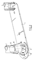
- Fig. 2 is a partly broken away detail view along arrow II in fig. 1.
- Fig. 3 is a perspective detail view along arrow III in fig. 1.
- Fig. 4-6 show views corresponding with fig. 3 of alternative embodiments.
- Shown in fig. 1 are two cubicle partitions 1 which are arranged at an interval adjacent to one another and which define between them a cubicle for a dairy cow.
- Each cubicle partition 1 comprises two upright pipes 2, 3 to the bottom end whereof is fixed a mounting plate 4.
- the cubicle partition 1 is screwed fixedly to the ground using the mounting plate 4.
- Extending at the top end of the upright pipes 2, 3 is a rail 5 forming one entity therewith. Together with the upright pipes 2, 3 the rail 5 is bent in further per se known manner from tube material.
- upright pipe 2 comprises a reinforcing foot 10 which extends converging towards the upright pipe, upwardly from the mounting plate 4.
- the reinforcing foot 10 is a frustro-conical body welded fixedly with its bottom end 13 onto the mounting plate 4.
- the reinforcing foot 10 is not welded to upright pipe 2.
- a join is formed between the upper edge 12 of reinforcing foot 10 and the upright pipe 2 during hot zinc-dipping of the manufactured cubicle partition 1, since the zinc in fact thereby forms a solder connection.
- a number of holes 14 are bored in the mounting plate 4.
- Likewise arranged in the reinforcing foot 10 close to the upper edge 12 are a number of holes for zinc.
- a cross pipe 6 is welded fixedly between the top ends of upright pipes 2, 3. This forms a reinforcement for the cubicle partition 1 and at the same time a passage guard which prevents the cattle accidentally walking through the cubicle partition 1, with the risk of damage this entails.
- the cubicle partitions 1 are curved with small bend radius.
- the bend radius of the inner bends lies generally in the order of magnitude of the thickness of the tube material.
- coupling 23 comprises two coupling parts 24 each having a U-shaped section with flanges bent transversely outward. In top view the coupling parts 24 are substantially square. Arranged in the flanges are four screw connection holes. These holes are positioned in accordance with the corner points of a square. It is hereby possible for the two coupling parts 24 to be connected by bolts 25 as shown with the flanges lying against one another turned through 90°.
- the coupling 23 forms a very stiff connection between the shoulder bar 22 and the rail 5 and thus contributes to the strength of the assembly of cubicle partitions and shoulder bar.
- a head bar is furthermore arranged at the front with similar couplings, which has an additional strengthening effect.
- a coupling of the type such as coupling 23 of fig. 3 tubes of different diameter can also be mutually connected.
- Such an embodiment is shown in fig. 4.
- the same shoulder bar 22 is here joined to a thicker tube 27.
- the coupling part 24 extending round the shoulder bar 22 remains unchanged.
- a coupling part 26 is used which has a correspondingly larger "U”.
- the holes in the fixing flanges are however arranged at the same mutual position so that the coupling part 24 can be connected thereto in similar manner. It will be apparent that by providing a limited number of different coupling parts such as 24 and 26 tubes of differing diameters can be rigidly connected to each other in random combinations.
- a square plate can be received between two coupling parts. As shown in fig. 5 this square plate 30 is provided with screw connection holes 31 lying in the same relative positions as the holes in the coupling parts 24. Tube engaging protrusions 32, 33 are formed in plate 30. As shown, these comprise a pair of parallel, upward protruding ribs 32 and a pair of parallel, downward protruding ribs 33. These tube engaging protrusions 32, 33 ensure a better clamping of the tubes relative to each other, whereby they can withstand greater mutual swivel and rotational forces.
- Fig. 6 shows an alternative wherein the intermediate plate 35 is made of hardened steel and provided with tube engaging protrusions in the form of sharp points 36 and 37 protruding to both sides.
- the bolts 25 are tightened these points 36, 37 grip into the tubes for connecting, whereby they are very well fixed.
- a so-called freely suspended cubicle partition with one upright pipe at a front end can also be embodied in favourable manner with a reinforcing foot according to the invention, whereby it can withstand heavier loads.
Description
- The invention relates to cubicle partition comprising at least one upright pipe and, connected thereto, a bracket-shaped rail bent from tube material, wherein a mounting plate is fixed to the bottom end of the upright pipe, said upright pipe comprising a reinforceing foot which extends converging towards the upright pipe upwardly from the mounting plate, along the bottom end of that upright pipe.
- Such a cubicle partition is known from NL-A-8 300 919. Cubicle partitions of this kind are used in so-called cubicle stalls to define cubicles or areas where cattle can lie down individually, for instance to ruminate.
- There is a clearly discernable trend in dairy cattle farming towards larger dairy cattle. This has the consequence that the cubicles and therefore the cubicle partitions must also become larger. In addition the cubicle partitions must also become stronger because of the heavier loads that can be expected from the larger cattle. In order to make the known cubicle partitions sufficiently rigid and strong, the mentioned reinforcing foot is arranged. This provides for a better resistance against bending the upright pipe and contributes to the overal rigidity and strength of the cubicle partition.
- The invention has for its object to provide a cubicle partition of the type specified in the preamble which has a further improved strength and rigidity with an efficient use of material.
- With the cubicle partition according to the invention this object is achieved with the characterizing measures of claim 1. By not fixedly welding the conical body at the top to the upright pipe but causing the connection to be brought about by means of the zinc applied during hot zinc-dipping, a construction is obtained wherein the bending loads on the upright pipe are absorbed equally by both the reinforcing foot and the upright pipe portion enclosed by the reinforcing foot.
- A further strengthening of the cubicle partition according to the invention is achieved with the step of claim 2. An additional advantage of the cross connection is that this prevents the cattle accidentally stepping between the two upright pipes and through the cubicle partition. This could lead to injuries.
- The invention also relates to and provides a cubicle stall comprising a number of cubicle partitions according to the invention disposed adjacently at mutual intervals. A cross pipe such as a shoulder bar is therein fitted at least along the tops of the adjacent cubicle partitions and connected to each thereof by couplings. According to a further development of the invention the step of
claim 3 is therein applied. By embodying the couplings in this manner a completely stiff connection of the cross pipe to the cubicle partitions is obtained, which contributes to the stiffness and strength of the assembly. - A further favourable development is therein characterized in
claim 4. - The invention is further elucidated in the following description with reference to the embodiments shown in the figures.
- Fig. 1 is a perspective view of a part of a cubicle stall with cubicle partitions according to the invention.
- Fig. 2 is a partly broken away detail view along arrow II in fig. 1.
- Fig. 3 is a perspective detail view along arrow III in fig. 1.
- Fig. 4-6 show views corresponding with fig. 3 of alternative embodiments.
- Shown in fig. 1 are two cubicle partitions 1 which are arranged at an interval adjacent to one another and which define between them a cubicle for a dairy cow.
- Each cubicle partition 1 comprises two
upright pipes 2, 3 to the bottom end whereof is fixed amounting plate 4. The cubicle partition 1 is screwed fixedly to the ground using themounting plate 4. Extending at the top end of theupright pipes 2, 3 is arail 5 forming one entity therewith. Together with theupright pipes 2, 3 therail 5 is bent in further per se known manner from tube material. - As fig. 2 shows in more detail, upright pipe 2 comprises a reinforcing
foot 10 which extends converging towards the upright pipe, upwardly from themounting plate 4. In the embodiment shown the reinforcingfoot 10 is a frustro-conical body welded fixedly with itsbottom end 13 onto themounting plate 4. At the location of itsupper edge 12 the reinforcingfoot 10 is not welded to upright pipe 2. A join is formed between theupper edge 12 of reinforcingfoot 10 and the upright pipe 2 during hot zinc-dipping of the manufactured cubicle partition 1, since the zinc in fact thereby forms a solder connection. In order to ensure that during zinc-plating the liquid zinc can flow properly into the interior of the reinforcing foot and the interior of the upright pipe 2 a number ofholes 14 are bored in themounting plate 4. Likewise arranged in the reinforcingfoot 10 close to theupper edge 12 are a number of holes for zinc. - Owing to the thus embodied strengthening it becomes possible to load upright pipe 2 considerably more, so that given the same material for the upright pipe 2 the cubicle partition 1 can take a larger form and/or is more robust.
- According to a further development a
cross pipe 6 is welded fixedly between the top ends ofupright pipes 2, 3. This forms a reinforcement for the cubicle partition 1 and at the same time a passage guard which prevents the cattle accidentally walking through the cubicle partition 1, with the risk of damage this entails. - As is shown in fig. 1, the cubicle partitions 1 are curved with small bend radius. The bend radius of the inner bends lies generally in the order of magnitude of the thickness of the tube material. Thus achieved is that both the head room 7 and the
body room 8 are of maximum size and therefore give maximum freedom to the cattle. - As fig. 1 shows, a
shoulder bar 22 is fitted along the tops of the adjacent cubicle partitions connected bycouplings 23 to each of therails 5 of the cubicle partitions 1 and 15. Thecoupling 23 used is shown in more detail in fig. 3. As can be seen therein,coupling 23 comprises twocoupling parts 24 each having a U-shaped section with flanges bent transversely outward. In top view thecoupling parts 24 are substantially square. Arranged in the flanges are four screw connection holes. These holes are positioned in accordance with the corner points of a square. It is hereby possible for the twocoupling parts 24 to be connected bybolts 25 as shown with the flanges lying against one another turned through 90°. Thecoupling 23 forms a very stiff connection between theshoulder bar 22 and therail 5 and thus contributes to the strength of the assembly of cubicle partitions and shoulder bar. As can be seen in the figures, a head bar is furthermore arranged at the front with similar couplings, which has an additional strengthening effect. - With a coupling of the type such as
coupling 23 of fig. 3 tubes of different diameter can also be mutually connected. Such an embodiment is shown in fig. 4. Thesame shoulder bar 22 is here joined to athicker tube 27. Thecoupling part 24 extending round theshoulder bar 22 remains unchanged. For the thicker tube 27 acoupling part 26 is used which has a correspondingly larger "U". The holes in the fixing flanges are however arranged at the same mutual position so that thecoupling part 24 can be connected thereto in similar manner. It will be apparent that by providing a limited number of different coupling parts such as 24 and 26 tubes of differing diameters can be rigidly connected to each other in random combinations. - For a still more rigid connection, according to a further development a square plate can be received between two coupling parts. As shown in fig. 5 this
square plate 30 is provided withscrew connection holes 31 lying in the same relative positions as the holes in thecoupling parts 24.Tube engaging protrusions plate 30. As shown, these comprise a pair of parallel, upward protrudingribs 32 and a pair of parallel, downward protrudingribs 33. Thesetube engaging protrusions - Fig. 6 shows an alternative wherein the
intermediate plate 35 is made of hardened steel and provided with tube engaging protrusions in the form ofsharp points bolts 25 are tightened thesepoints - The invention is not limited to the embodiments shown in the figures. A so-called freely suspended cubicle partition with one upright pipe at a front end can also be embodied in favourable manner with a reinforcing foot according to the invention, whereby it can withstand heavier loads.
Claims (4)
- Cubicle partition (1) comprising at least one upright pipe (2) and, connected thereto, a bracket-shaped rail (5) bent from tube material, wherein a mounting plate (4) is fixed to the bottom end of the upright pipe, said upright pipe (2) comprising a reinforcing foot (10) which extends converging towards the upright pipe upwardly from the mounting plate, along the bottom end of that upright pipe (2), characterized in that the reinforcing foot (10) is a frusto-conical body which extends round the upright pipe (2) and is welded fixedly to the mounting plate (4) and which is connected at the position of its upper edge to the upright pipe (2) by means of zinc arranged during hot zinc-dipping of the cubicle partition.
- Cubicle partition as claimed in claim 1, characterized in that it is of the type with two upright pipes (2, 3) and a rail (5) formed as a whole therewith and that a transverse connection such as a cross pipe (6) is arranged between the top ends of the two upright pipes (2, 3).
- Cubicle stall comprising a number of cubicle partitions (1) as claimed in claim 1 or 2 disposed adjacently at mutual intervals, wherein a transverse tube such as a shoulder bar (22) is fitted at least along the tops of the adjacent partitions and connected to each thereof by couplings (23), characterized in that each coupling (23) comprises two coupling parts with a U-shaped section with flanges bent transversely outward and a substantially square top view, wherein arranged in the flanges are screw connection holes going through on the corners of a square and wherein the coupling parts (24) are connected by bolts (25) with the flanges lying against one another turned over 90°.
- Cubicle stall as claimed in claim 3, characterized in that a square plate (35) is positioned between the two coupling parts which is provided with tube engaging protrusions (36, 37).
Priority Applications (1)
| Application Number | Priority Date | Filing Date | Title |
|---|---|---|---|
| EP92202745A EP0521587B1 (en) | 1990-01-19 | 1991-01-10 | Cubicle partition |
Applications Claiming Priority (2)
| Application Number | Priority Date | Filing Date | Title |
|---|---|---|---|
| NL9000142 | 1990-01-19 | ||
| NL9000142A NL9000142A (en) | 1990-01-19 | 1990-01-19 | LIGBOX SEPARATION. |
Related Child Applications (1)
| Application Number | Title | Priority Date | Filing Date |
|---|---|---|---|
| EP92202745.3 Division-Into | 1991-01-10 |
Publications (2)
| Publication Number | Publication Date |
|---|---|
| EP0438191A1 EP0438191A1 (en) | 1991-07-24 |
| EP0438191B1 true EP0438191B1 (en) | 1994-05-25 |
Family
ID=19856452
Family Applications (2)
| Application Number | Title | Priority Date | Filing Date |
|---|---|---|---|
| EP91200037A Expired - Lifetime EP0438191B1 (en) | 1990-01-19 | 1991-01-10 | Cubicle Partition |
| EP92202745A Expired - Lifetime EP0521587B1 (en) | 1990-01-19 | 1991-01-10 | Cubicle partition |
Family Applications After (1)
| Application Number | Title | Priority Date | Filing Date |
|---|---|---|---|
| EP92202745A Expired - Lifetime EP0521587B1 (en) | 1990-01-19 | 1991-01-10 | Cubicle partition |
Country Status (4)
| Country | Link |
|---|---|
| US (1) | US5111770A (en) |
| EP (2) | EP0438191B1 (en) |
| DE (2) | DE69102076T2 (en) |
| NL (1) | NL9000142A (en) |
Families Citing this family (32)
| Publication number | Priority date | Publication date | Assignee | Title |
|---|---|---|---|---|
| US5961248A (en) * | 1997-04-18 | 1999-10-05 | Tourtellotte; Mills C. | Structural member connection and method |
| FR2768485B1 (en) * | 1997-09-18 | 1999-12-10 | Cogema | SUPPORT SYSTEM FOR PIPING IN TECHNICAL GALLERIES, ESPECIALLY IN THE NUCLEAR INDUSTRY |
| FR2768473B1 (en) * | 1997-09-18 | 1999-12-03 | Cogema | ASSEMBLY DEVICE BETWEEN TWO TUBES |
| US5975026A (en) * | 1998-01-08 | 1999-11-02 | Merrill Equipment Company | Free stall divider |
| US6026766A (en) * | 1998-03-31 | 2000-02-22 | Albers, Jr.; Teo | Dairy freestall housing apparatus |
| US6347903B1 (en) | 1998-04-14 | 2002-02-19 | George Stuart Knighton | Fly clamp for reinforcing bars in concrete construction |
| FR2781331B1 (en) | 1998-07-22 | 2000-08-18 | Agritubel | SEPARATION ELEMENT FOR ADJUSTING THE DEPTH OF A SHELF |
| US6698964B2 (en) * | 1999-02-05 | 2004-03-02 | John DaSilveira | Variably configurable cattle stall connection |
| USD427386S (en) * | 1999-02-05 | 2000-06-27 | Dasilveira John D | Variably configurable cattle stall connector |
| US6467434B1 (en) * | 1999-12-20 | 2002-10-22 | Artex Fabricators Ltd. | Cattle handling system and method of installing same |
| US6318297B1 (en) * | 2000-01-26 | 2001-11-20 | John Hatfield | Livestock free stall and method for making the same |
| US6579032B1 (en) * | 2000-07-26 | 2003-06-17 | Solus Industrial Innovations, Llc | Low profile rod clamp |
| FR2843682B1 (en) * | 2002-08-21 | 2005-12-09 | Guerletub | ANIMAL LOGO SYSTEM, ESPECIALLY FOR BOVINE |
| DE102004010602A1 (en) * | 2003-03-20 | 2004-10-14 | Zimmermann Stalltechnik Gmbh | Stall separation unit for cows and bulls comprises a bent tube which lies in the foot area parallel to another tube which runs underneath the stall |
| US6925962B2 (en) * | 2003-09-19 | 2005-08-09 | Norbco, Inc. | Elevated beam cow stall assembly |
| US7411774B2 (en) * | 2004-06-01 | 2008-08-12 | Leeper Ii William F | Voltage variable capacitor |
| US7093727B2 (en) * | 2004-09-14 | 2006-08-22 | Musico M James | Plural utensils support system |
| US7784431B2 (en) * | 2005-02-09 | 2010-08-31 | Hatfield John B | Animal stanchion with selectively releasable feature |
| US7523895B1 (en) * | 2006-06-01 | 2009-04-28 | Automatic Fire Control, Incorporated | Sway brace and method for securing a pipe or conduit against sway |
| US7516922B1 (en) | 2006-11-03 | 2009-04-14 | Automatic Fire Control, Incorporated | Sway brace and method for securing a pipe or conduit against sway |
| GB0709881D0 (en) * | 2007-05-23 | 2007-07-04 | Gildernew Sean | Improvments in and relating to animal stalls |
| US7849819B2 (en) * | 2008-01-25 | 2010-12-14 | Norbco, Inc. | Brisket tube hanger for cow stall assembly |
| US8070113B1 (en) | 2009-03-30 | 2011-12-06 | Automatic Fire Control, Incorporated | Sway brace |
| US8579539B2 (en) * | 2009-08-10 | 2013-11-12 | Gea Farm Technologies, Inc. | Dairy freestall cross clamp assembly |
| US8646241B2 (en) * | 2011-03-18 | 2014-02-11 | Shelterlogic Corp. | Intercoupled piping assembly |
| JP2014126185A (en) * | 2012-12-27 | 2014-07-07 | Om Kiki Corp | Pipe connector |
| EP3135104B1 (en) * | 2015-08-25 | 2017-05-17 | Michael Earls | Flexible neckrail coupling |
| US10550581B2 (en) | 2016-02-09 | 2020-02-04 | Knoll, Inc. | Cork-based tile for privacy apparatuses and method of making and using the same |
| US10961700B2 (en) | 2017-02-27 | 2021-03-30 | Knoll, Inc. | Noise reduction apparatus and method of making and using the same |
| USD911492S1 (en) * | 2018-02-27 | 2021-02-23 | Kohler Co. | Bidet faucet |
| US11751538B2 (en) * | 2020-02-21 | 2023-09-12 | II Ronald Alan Meneou | Animal restraint device |
| WO2022192120A1 (en) | 2021-03-10 | 2022-09-15 | Knoll, Inc. | Work space disenfection apparatus and method |
Family Cites Families (18)
| Publication number | Priority date | Publication date | Assignee | Title |
|---|---|---|---|---|
| CA769848A (en) * | 1967-10-24 | Miller Leroy | Washer gain for timber structures | |
| US1839313A (en) * | 1929-08-13 | 1932-01-05 | Ney Mfg Company | Stall construction |
| US2164022A (en) * | 1937-12-10 | 1939-06-27 | Trumbull Electric Mfg Co | Electric connector |
| US2888722A (en) * | 1956-12-20 | 1959-06-02 | Malleable Iron Fittings Co | Washer gain for timber structures formed of round wood poles |
| US3415554A (en) * | 1966-10-17 | 1968-12-10 | Unistrut Corp | Structural joint assembly and connectors therefor |
| US3734439A (en) * | 1971-10-22 | 1973-05-22 | Aladdin Manuf Co | Beverage container receptacle and clamp |
| US4171684A (en) * | 1977-03-18 | 1979-10-23 | The De Laval Separator Company | Stall design of feeding station |
| US4241699A (en) * | 1979-03-30 | 1980-12-30 | Orchard Paul D | Cow-restraining device |
| FR2486769A1 (en) * | 1980-07-18 | 1982-01-22 | Fournier Sarl Expl Ets | Animal rearing building partition system - comprises plates individually held in floor by sole-plates and between posts at top |
| FR2492629B1 (en) * | 1980-10-29 | 1986-04-11 | Foenard Pierre | BOXES FOR BOVIDS |
| US4407601A (en) * | 1980-11-03 | 1983-10-04 | Commonwealth Edison Co. | Cross-arm brace |
| NL8100537A (en) * | 1981-02-04 | 1982-09-01 | Brouwers Bv L S | FENCING FOR SIDEWARD SEPARATION OF AN ACCESS SIDE LIGBOXES FOR PARTICULAR CATTLE. |
| US4350117A (en) * | 1981-03-02 | 1982-09-21 | Josef Hacker | Free stall construction |
| GB2094125A (en) * | 1981-03-11 | 1982-09-15 | King Gerard Oliver | Improvements in and relating to cow sheds |
| DE8207152U1 (en) * | 1982-03-13 | 1983-02-03 | Spinder, Tjipke, Harkema | MUSHROOM CURVED PARTITION PIPE FOR A CATTLE FARM |
| NL8201332A (en) * | 1982-03-30 | 1983-10-17 | Cornelis Leonardus Wilhelmus D | STABLE FURNITURE. |
| US4597140A (en) * | 1983-08-08 | 1986-07-01 | Girard Development Incorporated | Tube clamp |
| FR2573794A1 (en) * | 1984-11-27 | 1986-05-30 | Fournier Sarl Ets | Partition erecting base |
-
1990
- 1990-01-19 NL NL9000142A patent/NL9000142A/en not_active Application Discontinuation
-
1991
- 1991-01-10 DE DE69102076T patent/DE69102076T2/en not_active Expired - Fee Related
- 1991-01-10 EP EP91200037A patent/EP0438191B1/en not_active Expired - Lifetime
- 1991-01-10 DE DE69111599T patent/DE69111599T2/en not_active Expired - Fee Related
- 1991-01-10 EP EP92202745A patent/EP0521587B1/en not_active Expired - Lifetime
- 1991-01-14 US US07/640,880 patent/US5111770A/en not_active Expired - Fee Related
Also Published As
| Publication number | Publication date |
|---|---|
| EP0521587A2 (en) | 1993-01-07 |
| DE69111599D1 (en) | 1995-08-31 |
| DE69102076D1 (en) | 1994-06-30 |
| EP0521587B1 (en) | 1995-07-26 |
| DE69111599T2 (en) | 1996-01-11 |
| DE69102076T2 (en) | 1994-09-29 |
| NL9000142A (en) | 1991-08-16 |
| EP0521587A3 (en) | 1993-04-07 |
| US5111770A (en) | 1992-05-12 |
| EP0438191A1 (en) | 1991-07-24 |
Similar Documents
| Publication | Publication Date | Title |
|---|---|---|
| EP0438191B1 (en) | Cubicle Partition | |
| CA2031552C (en) | Elevated post base | |
| US8012065B2 (en) | Coupler | |
| FI87597B (en) | FOERBINDNINGSKONSTRUKTION FOER STAELLNINGSBOTTNARS VAOGRAETA STOED | |
| US7469658B2 (en) | Channel stanchion for elevated beam cow stall assembly | |
| US5470021A (en) | Cable support apparatus and method | |
| EP0437298B1 (en) | Cubicle partition | |
| US4452175A (en) | Post assembly for a parlor stall | |
| US4599972A (en) | Portable free stall | |
| EP0057490B1 (en) | Fencing for laterally partitioning a cubicle having an entrance side, in particular for cattle | |
| JP3803730B2 (en) | Steel pipe pile rebar connector | |
| EP1075178B1 (en) | Standing cubicle partitions | |
| EP1179106B1 (en) | Cage former and clamp therefor | |
| WO2004025049A1 (en) | Scaffold, and girder intended for such a scaffold, and method for building a scaffold | |
| EP0779026B1 (en) | Coupling | |
| DE3734733A1 (en) | Pipe support for at least one curved pipeline | |
| CN217056599U (en) | Building floor pump line horizontal fixation device | |
| JPH065477Y2 (en) | Reinforcing bar hardware | |
| EP1459623A2 (en) | Separation device for stalls of a stable | |
| JPH0424170Y2 (en) | ||
| JPH045622Y2 (en) | ||
| EP0322970A1 (en) | Cubicle separation | |
| DE8207152U1 (en) | MUSHROOM CURVED PARTITION PIPE FOR A CATTLE FARM | |
| JPH0422661Y2 (en) | ||
| JPS6135004Y2 (en) |
Legal Events
| Date | Code | Title | Description |
|---|---|---|---|
| PUAI | Public reference made under article 153(3) epc to a published international application that has entered the european phase |
Free format text: ORIGINAL CODE: 0009012 |
|
| AK | Designated contracting states |
Kind code of ref document: A1 Designated state(s): BE DE FR GB NL |
|
| 17P | Request for examination filed |
Effective date: 19920117 |
|
| 17Q | First examination report despatched |
Effective date: 19920225 |
|
| GRAA | (expected) grant |
Free format text: ORIGINAL CODE: 0009210 |
|
| AK | Designated contracting states |
Kind code of ref document: B1 Designated state(s): BE DE FR GB NL |
|
| XX | Miscellaneous (additional remarks) |
Free format text: TEILANMELDUNG 92202745.3 EINGEREICHT AM 09/09/92. |
|
| REF | Corresponds to: |
Ref document number: 69102076 Country of ref document: DE Date of ref document: 19940630 |
|
| ET | Fr: translation filed | ||
| PLBE | No opposition filed within time limit |
Free format text: ORIGINAL CODE: 0009261 |
|
| STAA | Information on the status of an ep patent application or granted ep patent |
Free format text: STATUS: NO OPPOSITION FILED WITHIN TIME LIMIT |
|
| 26N | No opposition filed | ||
| PGFP | Annual fee paid to national office [announced via postgrant information from national office to epo] |
Ref country code: GB Payment date: 19970314 Year of fee payment: 7 |
|
| PGFP | Annual fee paid to national office [announced via postgrant information from national office to epo] |
Ref country code: NL Payment date: 19970320 Year of fee payment: 7 |
|
| PGFP | Annual fee paid to national office [announced via postgrant information from national office to epo] |
Ref country code: DE Payment date: 19970327 Year of fee payment: 7 |
|
| PGFP | Annual fee paid to national office [announced via postgrant information from national office to epo] |
Ref country code: FR Payment date: 19970430 Year of fee payment: 7 |
|
| PGFP | Annual fee paid to national office [announced via postgrant information from national office to epo] |
Ref country code: BE Payment date: 19970505 Year of fee payment: 7 |
|
| PG25 | Lapsed in a contracting state [announced via postgrant information from national office to epo] |
Ref country code: GB Free format text: LAPSE BECAUSE OF NON-PAYMENT OF DUE FEES Effective date: 19980110 |
|
| PG25 | Lapsed in a contracting state [announced via postgrant information from national office to epo] |
Ref country code: FR Free format text: THE PATENT HAS BEEN ANNULLED BY A DECISION OF A NATIONAL AUTHORITY Effective date: 19980131 Ref country code: BE Free format text: LAPSE BECAUSE OF NON-PAYMENT OF DUE FEES Effective date: 19980131 |
|
| BERE | Be: lapsed |
Owner name: WEELINK JOHANNES MARTINUS WILLIBRORDUS Effective date: 19980131 |
|
| PG25 | Lapsed in a contracting state [announced via postgrant information from national office to epo] |
Ref country code: NL Free format text: LAPSE BECAUSE OF NON-PAYMENT OF DUE FEES Effective date: 19980801 |
|
| GBPC | Gb: european patent ceased through non-payment of renewal fee |
Effective date: 19980110 |
|
| NLV4 | Nl: lapsed or anulled due to non-payment of the annual fee |
Effective date: 19980801 |
|
| PG25 | Lapsed in a contracting state [announced via postgrant information from national office to epo] |
Ref country code: DE Free format text: LAPSE BECAUSE OF NON-PAYMENT OF DUE FEES Effective date: 19981001 |
|
| REG | Reference to a national code |
Ref country code: FR Ref legal event code: ST |