EP0437890A1 - Method for production of multicomponent materials - Google Patents
Method for production of multicomponent materials Download PDFInfo
- Publication number
- EP0437890A1 EP0437890A1 EP90203468A EP90203468A EP0437890A1 EP 0437890 A1 EP0437890 A1 EP 0437890A1 EP 90203468 A EP90203468 A EP 90203468A EP 90203468 A EP90203468 A EP 90203468A EP 0437890 A1 EP0437890 A1 EP 0437890A1
- Authority
- EP
- European Patent Office
- Prior art keywords
- target
- ultrafine particles
- particles
- substrate
- laser beam
- Prior art date
- Legal status (The legal status is an assumption and is not a legal conclusion. Google has not performed a legal analysis and makes no representation as to the accuracy of the status listed.)
- Withdrawn
Links
Images

Classifications
-
- C—CHEMISTRY; METALLURGY
- C23—COATING METALLIC MATERIAL; COATING MATERIAL WITH METALLIC MATERIAL; CHEMICAL SURFACE TREATMENT; DIFFUSION TREATMENT OF METALLIC MATERIAL; COATING BY VACUUM EVAPORATION, BY SPUTTERING, BY ION IMPLANTATION OR BY CHEMICAL VAPOUR DEPOSITION, IN GENERAL; INHIBITING CORROSION OF METALLIC MATERIAL OR INCRUSTATION IN GENERAL
- C23C—COATING METALLIC MATERIAL; COATING MATERIAL WITH METALLIC MATERIAL; SURFACE TREATMENT OF METALLIC MATERIAL BY DIFFUSION INTO THE SURFACE, BY CHEMICAL CONVERSION OR SUBSTITUTION; COATING BY VACUUM EVAPORATION, BY SPUTTERING, BY ION IMPLANTATION OR BY CHEMICAL VAPOUR DEPOSITION, IN GENERAL
- C23C16/00—Chemical coating by decomposition of gaseous compounds, without leaving reaction products of surface material in the coating, i.e. chemical vapour deposition [CVD] processes
- C23C16/44—Chemical coating by decomposition of gaseous compounds, without leaving reaction products of surface material in the coating, i.e. chemical vapour deposition [CVD] processes characterised by the method of coating
-
- C—CHEMISTRY; METALLURGY
- C23—COATING METALLIC MATERIAL; COATING MATERIAL WITH METALLIC MATERIAL; CHEMICAL SURFACE TREATMENT; DIFFUSION TREATMENT OF METALLIC MATERIAL; COATING BY VACUUM EVAPORATION, BY SPUTTERING, BY ION IMPLANTATION OR BY CHEMICAL VAPOUR DEPOSITION, IN GENERAL; INHIBITING CORROSION OF METALLIC MATERIAL OR INCRUSTATION IN GENERAL
- C23C—COATING METALLIC MATERIAL; COATING MATERIAL WITH METALLIC MATERIAL; SURFACE TREATMENT OF METALLIC MATERIAL BY DIFFUSION INTO THE SURFACE, BY CHEMICAL CONVERSION OR SUBSTITUTION; COATING BY VACUUM EVAPORATION, BY SPUTTERING, BY ION IMPLANTATION OR BY CHEMICAL VAPOUR DEPOSITION, IN GENERAL
- C23C14/00—Coating by vacuum evaporation, by sputtering or by ion implantation of the coating forming material
- C23C14/22—Coating by vacuum evaporation, by sputtering or by ion implantation of the coating forming material characterised by the process of coating
- C23C14/24—Vacuum evaporation
- C23C14/28—Vacuum evaporation by wave energy or particle radiation
Definitions
- the invention relates to a method for producing multicomponent solid materials, a substrate being coated with ultrafine particles.
- Ultrafine particles are understood to mean particles with diameters in the range from 1 to 100 nm; such particles are accordingly smaller than the particles of conventional fine powders and larger than clusters of atoms (Chikara Hayashi, J.Vac.Sci.Technol. A5 (4), Jul / Aug 1987, pp. 1375-1384, and Physics Today, December 1987, pp. 44-51).
- Hayashi ultrafine particles are produced using induction-heated crucibles, in arc furnaces, plasma furnaces and in the oxygen-enriched flames of burners, Hayashi prefers the GEM (Gas Evaporation Method) process, i.e. evaporation and condensation in a permanent gas.
- GEM Gas Evaporation Method
- Hayashi also describes the flotation and transportation of ultrafine particles in a gas stream and a gas coating process in which a high velocity gas stream carrying ultrafine particles with it at low pressure, e.g. 1 hPa, strikes a substrate.
- ultrafine particles with a diameter range from 5 to 65 nm are obtained, at 130 hPa those with a uniform particle diameter of 5 nm.
- the power density of the laser beam is between 104 and 107 W / cm2. Additional energy can also be supplied to the irradiated material, for example by an arc, by glow discharge or by electron beams.
- a method for coating a substrate in a vacuum chamber in which a target evaporates with the aid of a laser beam and the precipitate is used as a coating on the substrate, the laser radiation through an optical window into the vacuum chamber is introduced and the formation of precipitation on the window inside the vacuum chamber is avoided with the help of a gas cloud.
- the pressure level within the vacuum chamber is usually between 10 ⁇ 2 and 10 ⁇ 6 hPa.
- An inert gas or at least partially a reactive gas can be used as the gas for the gas cloud, which combines with the vaporized particles of the target to form a new chemical compound and is therefore a constituent the coating will be chosen.
- Materials of different melting temperature and evaporation temperature can evaporate side by side and can be used as a coating material.
- the target is either present as a solid mixture or as a powder consisting of a mixture of materials. Uniform wear and also control of the amount of evaporation dispensed per unit time can be controlled by moving the target. By moving the target, fresh materials are always exposed to the laser beam and holes are not burned into the target. Ionization of the vapors intended for the coating and accompanying inert gases is particularly advantageous for the transport of the vaporized particles from the target to the substrate.
- a low-pressure plasma can be formed at the evaporation point of the target and / or in the area of the substrate, which plasma is maintained, for example, by a glow discharge.
- the latter can be negatively charged.
- the laser material processing in high vacuum described in DE-A-38 00 680 provides particles of very unspecific size, i.e. Both those in the region larger than 1 .mu.m and molecules themselves. Furthermore, a sufficiently high mass flow in a high vacuum cannot be achieved.
- the object of the invention is to improve the production of multicomponent materials by the process mentioned at the beginning.
- the ultrafine particles are applied together with a further material component when coating the substrate, this component being formed by reactive deposition from an additional gas phase, i.e. by CVD, plasma-activated CVD or laser-induced CVD.
- a coating method is advantageous in which the substrates are coated with ultrafine particles made of several materials, the individual ultrafine particles either consisting of only one material or of several materials and the particles are then sintered by a heat treatment and thus compacted porously.
- ultrafine particles are applied without additional solidification in the form of crosslinked chain structures and chain ends adhering firmly to the substrate surface.
- CVI c hemical v apour i nfiltration means CVD inside the pores of a porous material, such as may, for example, containing particles chain also from the deposition of loose agglomerates formed.
- a porous material such as may, for example, containing particles chain also from the deposition of loose agglomerates formed.
- WF zB / H2 WF zB / H2
- the porous layer is heated to a temperature sufficient for thermal CVD either directly or inductively or by laser.
- CVI can be used either as an isothermal process, ie the entire substrate is at a constant temperature, or as a temperature gradient CVI, the temperature gradient generally being able to be shifted out of the zone of greatest deposition towards the "cold" inflowing reactive gas.
- the target is made of 4BaO .
- Al2O3 composed, in the last coating phase ultrafine particles are evaporated from another target from Sc2O3 and the other material component for solidifying the porous structure is tungsten, which is deposited via PCVD, CVD or CVI from WF6 / H2 or another gaseous W source . This is an example of the manufacture of alkaline earth replenishment cathodes in general.
- the ultrafine particles used in the process according to the invention can be produced by all of the processes mentioned at the outset, e.g. by laser beam evaporation from a target.
- An intensive, high-energy electron beam which emerges from a differentially pumped chamber and strikes the target, can also be used to generate particles, or else ion beams or sputtering.
- a method is preferred in which a laser beam is directed onto a target in such a way that the removal of the target material takes place in the same direction as the laser beam.
- the target material struck by the laser beam is completely removed in the direction of radiation, with most of the beam interacting with the target and only a small part directly through the target passes through or passes the target. Both a penetration and an edge removal can thus take place by moving the laser beam relative to the target in the target edge zone along the target edge and, with suitable setting of the laser parameters such as power, power density and the relative speed, completely removing the target edge in each case.
- the target thickness should not be greater than a few mm, typically 1 to 5 mm.
- a variant of the method according to the invention is that the evaporating ultra-fine particles flow through a hole in the target and, if appropriate, also through an additional aperture.
- the surface of the target is expediently roughened, sanded or oxidized before the removal begins, or a porous compact is used as the target. This is explained in more detail below.
- Another embodiment of the method according to the invention is that different material components evaporate simultaneously and ultrafine particles are generated therefrom.
- the target is expediently heated directly or indirectly (for example by resistance heating, inductive heating or laser beam heating).
- the laser beam evaporation from the target preferably takes place in front of, in or behind the focus of a focused beam, focusing in or outside a target chamber preferably using a spherical focusing mirror which is flushed with inert gas.
- the laser beam has a power profile on the target surface which consists of a narrow removal area with high power and a wider heating area with lower power.
- the ultrafine particles are preferably transferred to a substrate via a generally inert transport gas and, if appropriate, an intermediate size selection.
- the ultrafine particles are preferably given a size distribution with a standard deviation of at most 10% of the mean diameter, or only selected particles of this size distribution including their agglomerates reach the substrate.
- the ultrafine particles are preferably metered by adjusting the laser power density on the target impact surface, the size of the impact spot, the relative speed between the target and the laser beam, the total pressure in the target chamber and / or by dividing the carrier gas stream, it being advantageous to use the aforementioned variables to keep constant during the duration of the procedure.
- the total pressure in the target chamber is preferably set so low that the maximum of the size distribution coincides with the particle size to be selected.
- pressures of at most 20 hPa, in particular 10 to 1 hPa are set.
- the ultrafine particles With charges of the same sign and, in the case of oxidic particles or insulators, preferably to coat them beforehand with a thin, only a few monolayers thick, electrically conductive or metallic surface layer.
- the material component enveloping the ultrafine particles is preferably a material with solid solubility which is negligible in the particle material, as a result of which the size-dependent properties of the ultrafine particles are stabilized in the solid.
- the material to be transferred is evaporated by a laser beam with a high power density of 106 to 109 w / cm2 in the target's impact surface at a sufficiently high spot temperature, either ultrafine particles already being evaporated or ultrafine particles being formed from this material in the vapor phase, the ultrafine particles are transported via a gas stream or thermophoretically to a cold substrate and deposited there or, before precipitation, optionally coated and deposited by means of reactive deposition from the gas phase (CVD) with the aid of a plasma or in one
- CVD reactive deposition from the gas phase
- Plasma is broken down and deposited on the substrate. It is also possible to charge the ultrafine particles and selectively transport them using an electric field.
- the area of plasma shielding is undesirable for material processing because the process then becomes uncontrollable.
- the power density must also be sufficient for evaporation and particle formation, i.e.
- good regulation and adjustment of the power density in the impact surface is required.
- the particle formation in the gas phase occurs with supersaturated steam (i.e. when the partial pressure at the temperature T above the surface is significantly above the saturation vapor pressure), or small liquid droplets evaporate directly, which is particularly the case with materials such as Sc2O3 that decompose in the gas phase, is an advantage.
- these are: roughening or sanding the metal surface, oxidizing the metal surface so that a higher final temperature is reached at the beginning by higher power consumption, or irradiating a porous compact.
- Another way of increasing the infrared absorption in metals is to irradiate the target surface with a second laser of lower power in the visible. Since the laser effect on the target surface leads to a strong change such as ablation and hole formation and thus also to a temporal change in the amount of material evaporated, either the laser beam or the substrate relative to the laser beam is continuously moved in a meandering grid in order to obtain constant particle quantities.
- the particle detection using a HeNe laser beam by scattering on the particle surfaces and the resulting reduction in the intensity of the beam is described below. With small particles there is also the possibility of mass spectrometric detection and charging (with e - beam) or slight ionization. Further particle detection is possible by using the particle transfer and weighing the target and substrate after longer transfer times.
- the particle deposition takes place either via thermal diffusion on a cold substrate or with the aid of charged particles and an electrical voltage on the substrate electrode, or the particles are dissolved in a plasma or with the aid of a second CO2 or NdYAG laser and placed on a hot and / or suitable electrically polarized substrate deposited.
- the target plate can by a Additional heating 8 can be additionally heated as required.
- the target material With a power density of 106 to 107 watts / cm2 in focus, the target material is heated above the melting point, partially evaporates, and particles 9 form in the highly supersaturated vapor phase or particles 9 evaporate directly from the surface.
- the ZnSe window 3 is kept free of any vapor deposition layers by an inert purge gas (arrow 10) (insert 11 with nozzles for purge gas).
- the ultrafine particles 9 formed directly above the point of impact are transported by an inert transport gas 31, which is blown onto the target surface through a nozzle 12, through a heated suction opening (arrow 13) to a deposition chamber 14, where they strike a cooled substrate electrode 15 ( Cooling 16).
- a direct current or alternating current glow discharge can optionally be ignited between the substrate electrode 15 and the counter electrode 17 (voltage supply 18), and reactive gases for CVD or PCVD can additionally be let into the deposition chamber 14.
- Transport gases and reactive gases or gaseous reaction products are sucked off by a pump for gas disposal (arrow 19), and a pressure of about 1 to 100 hPa is maintained in the deposition chamber 14, while the pressure in the evaporator chamber 5 is about 100 to 1000 hPa (outlet pressure in the gas nozzle: some 105 Pa).
- the spot temperature is measured perpendicular to the area of incidence of the laser beam via an infrared pyrometer 20 (viewing window 21) and readjusted, for example, via the focus positioning.
- the target 7 is continuously computer-controlled, for example according to a meandering grid moved on.
- the resulting particles are, for example, a He-Ne laser beam 22, which enters the chamber 5 through a rinsed window 23 (rinsing insert not shown here) and parallel to the target plate 7 above the heated spot (beam height above the plate, for example, adjustable via a rotatable plane-parallel plate 24 is guided in front of the window 23) and strikes a photodetector 26 through a likewise rinsed viewing window 25, detected via light scattering and thus reduction in intensity of the HeNe beam.
- a He-Ne laser beam 22 enters the chamber 5 through a rinsed window 23 (rinsing insert not shown here) and parallel to the target plate 7 above the heated spot (beam height above the plate, for example, adjustable via a rotatable plane-parallel plate 24 is guided in front of the window 23) and strikes a photodetector 26 through a likewise rinsed viewing window 25, detected via light scattering and thus reduction in intensity of the HeNe beam.
- the portion of the CO2 laser beam reflected from the target surface is either reflected back onto the focal spot by a curved spherical concave mirror 27 or absorbed in an absorber 28 (e.g. Woodsches Horn) or "swamp" for more scattering surfaces.
- the polarization of the IR laser beam is expediently circular in order to avoid anisotropies during evaporation with a linearly polarized beam.
- a linearly polarized beam can also be used (see FIG. 3) and angles of incidence other than that shown in FIG. 1 can also be used.
- the plasma chamber (PCVD, CVD) and deposition chamber can also be arranged one after the other spatially separated from one another.
- the target plate 7 is a round "plate” which is rotatable at the angular velocity about the axis 29 shown there, the axis can also be linearly displaced parallel to the point of incidence of the laser beam .
- the point of impact is usually eccentric.
- FIG. 2 Another arrangement is shown in FIG. 2.
- the NdYAG or CO2 laser beam 1 does not strike almost vertically as in FIG. 1, but is focused in a weakly grazing incidence in the focus area in a correspondingly narrowed target nozzle 30.
- An inert (or reactive) transport gas 31 enters the target chamber 5 and flows out through the target nozzle 30 into the deposition chamber 14 and thereby transports the particles 9 formed in (and after the) hole to the substrate surface 15.
- the flat grazing incidence has the advantage of up to 50 times higher electric field strength on the surface compared to the vertical incidence, but of course the disadvantage of the area intensity decreasing with the angle of incidence.
- the target cone nozzle insert can be displaced in the beam incidence direction via a linear feedthrough, not shown in FIG. 2 - sliding in sealing rings 4.
- a focus shift can also be achieved by a linear shift of the converging lens 2 on the beam axis.
- a He-Ne laser beam 22 is irradiated directly behind the cone nozzle opening for particle detection, and the formation of particles is reduced of the beam registered.
- the substrate electrode 15, on which the particle beam strikes, is provided with a variable temperature setting 16 (cooling or heating) and can be displaced linearly in all three spatial directions (device 6 ').
- a counter electrode 17 enables a direct or alternating voltage (voltage supply 18) to be applied between the latter and the substrate 15 and thus the formation of a glow discharge.
- reactive gases can be introduced (not shown here), and the particles can be coated by CVD or PCVD or dissolved in the plasma and deposited on the substrate.
- the target 7 is a thin, linearly displaceable metal sheet on which the CO2 laser beam 1 in focus, slightly inclined to the surface normal, impinges, a focus adjustment by a relative displacement of the ZnSe Converging lens (Ge converging lens) 2 is reached in the direction of the beam axis. Due to the angle between the beam axis and target normal of a few degrees, back reflections of the laser beam and thus possible power fluctuations are avoided.
- the jet inlet window 3 (ZnSe) is also flushed from the inside with an inert flushing gas via a flushing gas nozzle insert 11 in order to avoid window coatings.
- the target 7 is arranged in the center of a three-dimensional crosspiece 32.
- the focal spot temperature is controlled via a pyrometer 20 by measuring the temperature on the back of the sheet (at the focal spot 33), and the focus is thus in the Usually readjusted to maximum temperature.
- a catcher plate 34 sits opposite the target 7 in the pumping direction 19, covers almost the entire pump cross section in a version according to the invention, with the exception of a central round aperture opening, behind which the actual substrate is seated.
- a particle blowing out in the direction of the collector can also be achieved via a transport gas nozzle 35.
- FIGS. 4a and 4b An arrangement for embedding ultrafine particles 9, e.g. BaO or Sc2O3 or SiO2, e.g. Tungsten layer (or other metal layer) deposited via thermal CVD is shown in FIGS. 4a and 4b. It contains an inert transport gas, e.g. Argon, indicated by arrows 31. Between a (x-y) displaceable target 7, e.g. made of SiO2, BaO or Sc2O3, and a heated substrate 15, a fixed aperture 36 is arranged with an aperture 37 for forced transport gas flow.
- a (x-y) displaceable target 7 e.g. made of SiO2, BaO or Sc2O3
- a heated substrate a fixed aperture 36 is arranged with an aperture 37 for forced transport gas flow.
- ultrafine particles are not only evaporated from the surface of the target, but the target is totally pierced by the laser beam and the continuous delivery of ultrafine particles takes place by relative movement of the target perpendicular to the fixed laser beam (focus).
- the also fixed aperture behind the target with an opening in the area of the laser beam causes the inert transport gas to flow into the reaction / sedimentation chamber only through this opening, in which ultrafine particles are currently being evaporated, and not through the stomata already cut into the target .
- the inert transport gas transferring the ultrafine particles of target material e.g. BaO, Sc2O3 then strikes a substrate on which tungsten e.g. from WF6 + H2 (arrow 38) is deposited via CVD, here thermal CVD, and grows around the ultrafine particles also striking, so that a material structure of W with BaO / Sc2O3 particle embeddings is formed.
- target material e.g. BaO, Sc2O3
- alkaline earth replenishment cathodes can be produced in a single continuous process which replaces the many previous individual steps in the production, such as powder pressing and sintering for the porous W matrix, impregnation, application of the cover layer. This makes I-cathodes accessible for mass production.
- FIG. 4c in the arrangement according to FIGS. 4a and 4b, the target 7, which incidentally can also lie loosely on the diaphragm 36, is replaced by a target made of four different layers.
- target plates each consisting of BaO (1 mm thick), CaO (0.5 mm thick) and Al2O3 (0.5 mm thick), loosely stacked on top of each other and are shifted relative to the laser spot, for example in a meandering shape.
- these targets are relatively porous compacts.
- a target compact can also be used, which consists of a mixture of BaO: CaO: Al2O3 in a ratio of 4: 1: 1.
- the following process parameters were set: substrate temperature 500 to 600 ° C, WF6 flow 50 sccm, H2 flow 500 sccm, Ar flow 300 sccm, pressure in the deposition chamber part 14 10 to 20 hPa, pressure in the area 5 of the inflowing transport gas 100 to 200 hPa, Laser power 50 watts, focal length of the focusing lens 5.2 cm.
- substrate temperature 500 to 600 ° C WF6 flow 50 sccm, H2 flow 500 sccm, Ar flow 300 sccm
- pressure in the deposition chamber part 14 10 to 20 hPa pressure in the area 5 of the inflowing transport gas 100 to 200 hPa
- Laser power 50 watts focal length of the focusing lens 5.2 cm.
- a target removal rate of 0.07 g / min and a W deposition rate of about 0.3 g / min 1 mm thick I-cathode layers can be produced on an area of about 1 cm2 in a coating time of about
- the cover layer can also be deposited with 4 BaO.CaO.Al2O3 targets pulled out.
- the substrate is usually peeled off, either mechanically or by selective etching, or by using a substrate on which the W-CVD + particle embedding layer does not adhere.
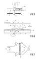
- FIG. 5 shows how target material struck by a laser beam 1 is completely removed in the radiation direction, the major part of the beam interacting with the target and only a small part 1 'passing the residual target 7'. Edge removal is thus carried out by the laser beam in relation to the target the target edge zone is moved along the target edge (arrow 39) and, with suitable setting of the laser parameters such as power, power density and the relative speed, completely removes the target edge.
- the already removed target part is designated 7 ".
- a layer 41 of ultrafine particles (FIG. 6) or of chain-containing agglomerates 41 '(FIG. 7) is deposited on or on a porous substrate 15' from a particle stream 40 with inert carrier gas.
- the layers 41 and 41 'and the porous substrates 15' are exposed to a reactive gas, e.g. WF6 / H2, flows through (arrows 38).
- 42 means an ohmic heating winding and 43 a coil for inductive heating.
- the separation of agglomerates of ultrafine particles and the CVI solidification can also be carried out in succession.
Landscapes
- Chemical & Material Sciences (AREA)
- Metallurgy (AREA)
- Chemical Kinetics & Catalysis (AREA)
- Engineering & Computer Science (AREA)
- Materials Engineering (AREA)
- Mechanical Engineering (AREA)
- Organic Chemistry (AREA)
- General Chemical & Material Sciences (AREA)
- Health & Medical Sciences (AREA)
- Toxicology (AREA)
- Physical Vapour Deposition (AREA)
- Chemical Vapour Deposition (AREA)
- Physical Or Chemical Processes And Apparatus (AREA)
- Manufacture Of Metal Powder And Suspensions Thereof (AREA)
Abstract
Description
Die Erfindung betrifft ein Verfahren zum Herstellen von mehrkomponentigen festen Materialien, wobei ein Substrat mit ultrafeinen Partikeln beschichtet wird.The invention relates to a method for producing multicomponent solid materials, a substrate being coated with ultrafine particles.
Unter ultrafeinen Partikeln sind Partikel mit Durchmessern im Bereich von 1 bis 100 nm zu verstehen; derartige Partikel sind demnach kleiner als die Partikel konventioneller feiner Pulver und größer als Cluster von Atomen (Chikara Hayashi, J.Vac.Sci.Technol. A5(4), Jul/Aug 1987, S. 1375-1384, und Physics Today, December 1987, S. 44-51).Ultrafine particles are understood to mean particles with diameters in the range from 1 to 100 nm; such particles are accordingly smaller than the particles of conventional fine powders and larger than clusters of atoms (Chikara Hayashi, J.Vac.Sci.Technol. A5 (4), Jul / Aug 1987, pp. 1375-1384, and Physics Today, December 1987, pp. 44-51).
Anwendungsmöglichkeiten für ultrafeine Partikel bestehen laut Hayashi a.a.O.
- in Farbstoffen, Pigmenten, Klebstoffen und Katalysatoren,
- für ultrafeine Partikel aus Al₂O₃, carburiertem Wolfram, Si₃N₄ und anderen hitze- und säurebeständigen Carbiden und Nitriden von aktiven Metallen und Seltenerdmetallen in Werkzeugen, Keramiken und hitzebeständigen Materialien,
- zum Dispersionshärten, wobei ultrafeine Partikel aus einem Wirtsmaterial dispergiert werden und die Mischung gesintert oder der Einwirkung eines Katalysators ausgesetzt wird,
- in Aerosolen für Land- und Forstwirtschaft, Militärtechnik und Medizin,
- für ultrafeine Partikel aus magnetischen Legierungen in magnetischen Aufzeichnungsmaterialien, z.B. Ton- und Videobänder, und
- in der Mikrobiologie.
- in dyes, pigments, adhesives and catalysts,
- for ultrafine particles made of Al₂O₃, carburized tungsten, Si₃N₄ and other heat and acid resistant carbides and nitrides of active metals and rare earth metals in tools, ceramics and heat resistant materials,
- for dispersion hardening, where ultrafine particles are dispersed from a host material and the mixture is sintered or subjected to the action of a catalyst,
- in aerosols for agriculture and forestry, military technology and medicine,
- for ultrafine particles made of magnetic alloys in magnetic recording materials, for example audio and video tapes, and
- in microbiology.
Die Herstellung von ultrafeinen Partikeln erfolgt laut Hayashi mit induktionsbeheizten Tiegeln, in Lichtbogenöfen, Plasmaöfen und in den mit Sauerstoff angereicherten Flammen von Brennern, wobei Hayashi das GEM-Verfahren (Gas Evaporation Method) bevorzugt, d.h. die Verdampfung und Kondensation in einem permanenten Gas.According to Hayashi, ultrafine particles are produced using induction-heated crucibles, in arc furnaces, plasma furnaces and in the oxygen-enriched flames of burners, Hayashi prefers the GEM (Gas Evaporation Method) process, i.e. evaporation and condensation in a permanent gas.
Ferner beschreibt Hayashi die Flotation und den Transport von ultrafeinen Partikeln in einem Gasstrom sowie ein Gas-Beschichtungsverfahren, bei dem ein Gasstrom hoher Geschwindigkeit, der ultrafeine Partikel mit sich führt, bei niedrigem Druck, z.B. 1 hPa, auf ein Substrat aufprallt.Hayashi also describes the flotation and transportation of ultrafine particles in a gas stream and a gas coating process in which a high velocity gas stream carrying ultrafine particles with it at low pressure, e.g. 1 hPa, strikes a substrate.
Aus US-A-4 619 691 ist ein Verfahren zum Herstellen von ultrafeinen Partikeln durch Bestrahlen einer Oberfläche eines Materials mit einem Laserstrahl bekannt. Wenn die Bestrahlung in einer entsprechend gewählten Gasatmosphäre, z.B. in Sauerstoff, Stickstoff, Dichlordifluormethan, Methan oder Propan, durchgeführt wird, werden ultrafeine Partikel mit einer gewünschten Zusammensetzung erhalten, wobei die Zusammensetzung entweder gleich der oder unterschiedlich von der Zusammensetzung des bestrahlten Materials ist. Die Partikelgrößenverteilung wird über den Druck der Gasatmosphäre eingestellt, wobei dieser Druck nicht größer als 1000 hPa ist. Bei der Bestrahlung von Titan unter einem Druck von 1000 hPa werden ultrafeine Partikel mit einem Durchmesserbereich von 5 bis 65 nm erhalten, bei 130 hPa solche mit einem einheitlichen Partikeldurchmesser von 5 nm. Die Leistungsdichte des Laserstrahls liegt zwischen 10⁴ und 10⁷ W/cm². Dem bestrahlten Material kann noch zusätzliche Energie zugeführt werden, z.B. durch einen Lichtbogen, durch Glimmentladung oder durch Elektronenstrahlen.From US-A-4 619 691 a method for producing ultrafine particles by irradiating a surface of a material with a laser beam is known. If the irradiation is carried out in an appropriately selected gas atmosphere, for example in oxygen, nitrogen, dichlorodifluoromethane, methane or propane, ultrafine particles having a desired composition are obtained, the composition being either the same as or different from the composition of the irradiated material. The particle size distribution is adjusted via the pressure of the gas atmosphere, whereby this Pressure is not greater than 1000 hPa. When titanium is irradiated under a pressure of 1000 hPa, ultrafine particles with a diameter range from 5 to 65 nm are obtained, at 130 hPa those with a uniform particle diameter of 5 nm. The power density of the laser beam is between 10⁴ and 10⁷ W / cm². Additional energy can also be supplied to the irradiated material, for example by an arc, by glow discharge or by electron beams.
Aus DE-A-38 00 680 ist ein Verfahren zur Beschichtung eines Substrats in einer Vakuumkammer bekannt, bei dem mit Hilfe eines Laserstrahls ein Target verdampft und der Niederschlag als Beschichtung auf dem Substrat ausgenutzt wird, wobei die Laserstrahlung durch ein optisches Fenster in die Vakuumkammer eingeführt wird und die Niederschlagsbildung auf dem Fenster innerhalb der Vakuumkammer mit Hilfe einer Gaswolke vermieden wird. Das Druckniveau innerhalb der Vakuumkammer liegt im Regelfall zwischen 10⁻² und 10⁻⁶ hPa. Als Gas für die Gaswolke kann ein Inertgas oder zumindest teilweise ein reaktives Gas, das sich mit den verdampften Partikeln des Targets zu einer neuen chemischen Verbindung vereinigt und damit Bestandteil der Beschichtung wird, gewählt werden. Es können Materialien unterschiedlicher Schmelztemperatur und Verdampfungstemperatur nebeneinander verdampfen und als Beschichtungswerkstoff eingesetzt werden. Dabei ist das Target entweder als Festkörpergemisch vorhanden oder als ein Pulver, das aus einem Gemisch von Materialien besteht. Eine gleichmäßige Abnutzung und auch eine Steuerung der Abgabemenge an Verdampfung pro Zeiteinheit können durch Bewegen des Targets gesteuert werden. Durch das Bewegen des Target sind stets frische Materialien dem Laserstrahl ausgesetzt und es wird das Einbrennen von Löchern in das Target vermieden. Für den Transport der verdampften Partikel vom Target zum Substrat ist eine Ionisierung der für die Beschichtung vorgesehenen Dämpfe und begleitender Inertgase besonders vorteilhaft. Um die Ionisierung zu unterstützen, kann an der Verdampfungsstelle des Targets und/oder im Bereich des Substrats ein Niederdruckplasma gebildet werden, das beispielsweise durch eine Glimmentladung aufrechterhalten wird. Zur weiteren Unterstützung des Transports der verdampften Partikel auf das Substrat kann letzteres negativ geladen sein.From DE-A-38 00 680 a method for coating a substrate in a vacuum chamber is known, in which a target evaporates with the aid of a laser beam and the precipitate is used as a coating on the substrate, the laser radiation through an optical window into the vacuum chamber is introduced and the formation of precipitation on the window inside the vacuum chamber is avoided with the help of a gas cloud. The pressure level within the vacuum chamber is usually between 10⁻² and 10⁻⁶ hPa. An inert gas or at least partially a reactive gas can be used as the gas for the gas cloud, which combines with the vaporized particles of the target to form a new chemical compound and is therefore a constituent the coating will be chosen. Materials of different melting temperature and evaporation temperature can evaporate side by side and can be used as a coating material. The target is either present as a solid mixture or as a powder consisting of a mixture of materials. Uniform wear and also control of the amount of evaporation dispensed per unit time can be controlled by moving the target. By moving the target, fresh materials are always exposed to the laser beam and holes are not burned into the target. Ionization of the vapors intended for the coating and accompanying inert gases is particularly advantageous for the transport of the vaporized particles from the target to the substrate. In order to support the ionization, a low-pressure plasma can be formed at the evaporation point of the target and / or in the area of the substrate, which plasma is maintained, for example, by a glow discharge. To further support the transport of the vaporized particles onto the substrate, the latter can be negatively charged.
Die in DE-A-38 00 680 beschriebene Lasermaterialbearbeitung im Hochvakuum liefert Partikel sehr unspezifischer Größe, d.h. sowohl solche im Bereich größer als 1 um als auch Moleküle selbst. Ferner läßt sich ein ausreichend hoher Massenfluß im Hochvakuum nicht bewerkstelligen.The laser material processing in high vacuum described in DE-A-38 00 680 provides particles of very unspecific size, i.e. Both those in the region larger than 1 .mu.m and molecules themselves. Furthermore, a sufficiently high mass flow in a high vacuum cannot be achieved.
Die Erfindung hat die Aufgabe, die Herstellung von mehrkomponentigen Materialien nach dem eingangs genannten Verfahren zu verbessern.The object of the invention is to improve the production of multicomponent materials by the process mentioned at the beginning.
Diese Aufgabe wird erfindungsgemäß dadurch gelöst, daß die ultrafeinen Partikel beim Beschichten des Substrats zusammen mit einer weiteren Materialkomponente aufgebracht werden, wobei diese Komponente durch reaktive Abscheidung aus einer zusätzlichen Gasphase, d.h. durch CVD, plasma-aktivierte CVD oder laser-induzierte CVD, mit aufgebracht wird.This object is achieved in that the ultrafine particles are applied together with a further material component when coating the substrate, this component being formed by reactive deposition from an additional gas phase, i.e. by CVD, plasma-activated CVD or laser-induced CVD.
Bei einer anderen Ausgestaltung des Beschichtens werden zuerst die ultrafeinen Partikel aufgebracht; anschließend erfolgt eine Verfestigung mit Hilfe von CVI = chemical vapour infiltration.In another embodiment of the coating, the ultrafine particles are applied first; followed by a solidification by means of CVI = c hemical v apour i nfiltration.
Ferner ist ein Beschichtungsverfahren vorteilhaft, bei dem die Substrate mit ultrafeinen Partikeln aus mehreren Materialien beschichtet werden, wobei die einzelnen ultrafeinen Partikel entweder nur aus einem Material oder aus mehreren Materialien bestehen und die Partikel anschließend durch eine Wärmebehandlung gesintert und damit porös kompaktiert werden.Furthermore, a coating method is advantageous in which the substrates are coated with ultrafine particles made of several materials, the individual ultrafine particles either consisting of only one material or of several materials and the particles are then sintered by a heat treatment and thus compacted porously.
Eine weitere Beschichtungsmöglichkeit besteht darin, daß die ultrafeinen Partikel ohne zusätzliche Verfestigung in Form von auf der Substratoberfläche fest haftenden vernetzten Kettenstrukturen und Kettenenden aufgebracht werden.Another coating option is that the ultrafine particles are applied without additional solidification in the form of crosslinked chain structures and chain ends adhering firmly to the substrate surface.
CVI = chemical vapour infiltration bedeutet CVD im Innern der Poren eines porösen Materials, wie es z.B. auch aus der Abscheidung von lockeren Partikelketten-haltigen Agglomeraten entstehen kann. Bei Agglomeraten von Ketten von BaO-, CaO- und/oder Al₂O₃-haltigen ultrafeinen Partikeln wird als reaktives Gas z.B. WF₆/H₂ zum Umhüllen der Partikelketten verwendet. Die poröse Schicht wird dabei auf für thermische CVD ausreichende Temperatur entweder direkt oder induktiv oder per Laser aufgeheizt. Bei der Abscheidung obiger Agglomerate ist eine zusätzliche Größenselektion in der Regel nicht erwünscht, der Prozeß wird also wesentlich vereinfacht. CVI kann entweder als isothermes Verfahren, d.h. das ganze Substrat befindet sich auf konstanter Temperatur, oder als Temperaturgradienten-CVI angewendet werden, wobei der Temperaturgradient in der Regel aus der Zone der stärksten Deposition heraus zum "kalten" einströmenden reaktiven Gas hin verschoben werden kann.CVI = c hemical v apour i nfiltration means CVD inside the pores of a porous material, such as may, for example, containing particles chain also from the deposition of loose agglomerates formed. In agglomerates of chains of BaO, CaO and / or Al₂O₃-containing ultrafine particles, WF zB / H₂, for example, is used as the reactive gas for enveloping the particle chains. The porous layer is heated to a temperature sufficient for thermal CVD either directly or inductively or by laser. When separating the above agglomerates, an additional size selection is generally not desirable, so the process is considerably simplified. CVI can be used either as an isothermal process, ie the entire substrate is at a constant temperature, or as a temperature gradient CVI, the temperature gradient generally being able to be shifted out of the zone of greatest deposition towards the "cold" inflowing reactive gas.
Um eine aus 4BaO . CaO . Al₂O₃ bestehende gefüllte Porenstruktur in einer W-Matrix mit Sc₂O₃ + W-Deckschicht zu erhalten, die als Scandat-Glühkathode gut geeignet ist und bei der Herstellung den Vorteil aufweist, in einem einzigen Abscheidungsprozeß aus der Gasphase hergestellt zu werden, wird das Target aus 4BaO . CaO . Al₂O₃ zusammengesetzt, wobei in der letzten Beschichtungsphase ultrafeine Partikel aus einem weiteren Target aus Sc₂O₃ verdampft werden und die weitere Materialkomponente zum Verfestigen der porösen Struktur Wolfram ist, das über PCVD, CVD oder CVI aus WF₆/H₂ oder einer anderen gasförmigen W-Quelle abgeschieden wird. Dies ist ein Beispiel für die Herstellung von Erdalkali-Nachlieferungskathoden ganz allgemein.To one from 4BaO. CaO. To get Al₂O₃ existing filled pore structure in a W matrix with Sc₂O₃ + W top layer, which is well suited as a Scandat hot cathode and has the advantage in the production to be produced in a single deposition process from the gas phase, the target is made of 4BaO . CaO. Al₂O₃ composed, in the last coating phase ultrafine particles are evaporated from another target from Sc₂O₃ and the other material component for solidifying the porous structure is tungsten, which is deposited via PCVD, CVD or CVI from WF₆ / H₂ or another gaseous W source . This is an example of the manufacture of alkaline earth replenishment cathodes in general.
Die beim erfindungsgemäßen Verfahren verwendeten ultrafeinen Partikel sind nach allen eingangs genannten Verfahren herstellbar, z.B. durch Laserstrahlverdampfung aus einem Target. Auch kann ein intensiver hochenergetischer Elektronenstrahl, der aus einer differentiell gepumpten Kammer austritt und auf das Target auftritt, zur Partikelerzeugung benutzt werden, oder auch Ionenstrahlen oder Sputtern. Bevorzugt wird jedoch ein Verfahren, bei dem ein Laserstrahl derart auf ein Target gerichtet wird, daß die Abtragung des Targetmaterials in gleichlaufender Richtung wie der Laserstrahl erfolgt.The ultrafine particles used in the process according to the invention can be produced by all of the processes mentioned at the outset, e.g. by laser beam evaporation from a target. An intensive, high-energy electron beam, which emerges from a differentially pumped chamber and strikes the target, can also be used to generate particles, or else ion beams or sputtering. However, a method is preferred in which a laser beam is directed onto a target in such a way that the removal of the target material takes place in the same direction as the laser beam.
Dabei wird vom Laserstrahl getroffenes Targetmaterial in Strahlungsrichtung vollständig abgetragen, wobei der größte Teil des Strahls mit dem Target in Wechselwirkung tritt und nur ein kleiner Teil direkt durch das Target hindurchtritt oder am Target vorbeigeht. Es kann also sowohl ein Durchschuß als auch eine Randabtragung erfolgen, indem der Laserstrahl relativ zum Target in der Targetrandzone am Targetrand entlangbewegt wird und bei geeigneter Einstellung der Laserparameter wie Leistung, Leistungsdichte sowie der Relativgeschwindigkeit den Targetrand jeweils komplett abträgt. Die Targetdicke sollte nicht größer als einige mm sein, typischerweise 1 bis 5 mm.The target material struck by the laser beam is completely removed in the direction of radiation, with most of the beam interacting with the target and only a small part directly through the target passes through or passes the target. Both a penetration and an edge removal can thus take place by moving the laser beam relative to the target in the target edge zone along the target edge and, with suitable setting of the laser parameters such as power, power density and the relative speed, completely removing the target edge in each case. The target thickness should not be greater than a few mm, typically 1 to 5 mm.
Eine Variante des erfindungsgemäßen Verfahrens ist, daß die abdampfenden ultrafeinen Partikel durch ein Loch im Target hindurch und gegebenenfalls noch durch eine zusätzliche Blende abströmen.A variant of the method according to the invention is that the evaporating ultra-fine particles flow through a hole in the target and, if appropriate, also through an additional aperture.
Zweckmäßigerweise wird die Oberfläche des Targets vor Beginn der Abtragung aufgerauht, geschmirgelt oder oxidiert, oder es wird als Target ein poröser Preßling verwendet. Dies wird weiter unten näher erläutert.The surface of the target is expediently roughened, sanded or oxidized before the removal begins, or a porous compact is used as the target. This is explained in more detail below.
Eine weitere Ausgestaltung des erfindungsgemäßen Verfahrens besteht darin, daß verschiedene Materialkomponenten gleichzeitig verdampft und ultrafeine Partikel daraus erzeugt werden.Another embodiment of the method according to the invention is that different material components evaporate simultaneously and ultrafine particles are generated therefrom.
Um eine Rückkondensation der ultrafeinen Partikel und thermomechanische Spannungen zu vermeiden oder zu reduzieren, wird das Target zweckmäßigerweise direkt oder indirekt (z.B. durch Widerstandsheizung, induktive Heizung oder Laserstrahlheizung) aufgeheizt.In order to avoid or reduce back-condensation of the ultrafine particles and thermomechanical voltages, the target is expediently heated directly or indirectly (for example by resistance heating, inductive heating or laser beam heating).
Die Laserstrahlverdampfung aus dem Target erfolgt vorzugsweise vor, im oder hinter dem Fokus eines fokussierten Strahls, wobei die Fokussierung in oder außerhalb einer Targetkammer vorzugsweise durch einen sphärischen fokussierenden Spiegel, der mit Inertgas gespült wird, erfolgt.The laser beam evaporation from the target preferably takes place in front of, in or behind the focus of a focused beam, focusing in or outside a target chamber preferably using a spherical focusing mirror which is flushed with inert gas.
Insbesondere für Keramiken ist es vorteilhaft, daß der Laserstrahl ein Leistungsprofil auf der Targetoberfläche aufweist, das aus einem schmalen Abtragbereich mit hoher Leistung und einem breiteren Heizbereich mit niedrigerer Leistung besteht.It is particularly advantageous for ceramics that the laser beam has a power profile on the target surface which consists of a narrow removal area with high power and a wider heating area with lower power.
Die ultrafeinen Partikel werden vorzugsweise über ein in der Regel inertes Transportgas und eine gegebenenfalls zwischengeschaltete Größenselektion zu einem Substrat überführt.The ultrafine particles are preferably transferred to a substrate via a generally inert transport gas and, if appropriate, an intermediate size selection.
Den ultrafeinen Partikeln wird vorzugsweise eine Größenverteilung mit einer Standardabweichung von höchstens 10% des mittleren Durchmessers erteilt oder es gelangen nur selektierte Partikel dieser Größenverteilung inclusive deren Agglomerate zum Substrat.The ultrafine particles are preferably given a size distribution with a standard deviation of at most 10% of the mean diameter, or only selected particles of this size distribution including their agglomerates reach the substrate.
Eine Dosierung der ultrafeinen Partikel erfolgt vorzugsweise durch Einstellung der Laserleistungsdichte auf der Targetauftrefffläche, der Größe des Auftreffflecks, der Relativgeschwindigkeit zwischen Target und Laserstrahl, des Gesamtdrucks in der Targetkammer und/oder durch eine Aufteilung des Trägergasstromes, wobei es vorteilhaft ist, die zuvor genannten Größen während der Verfahrensdauer konstant zu halten.The ultrafine particles are preferably metered by adjusting the laser power density on the target impact surface, the size of the impact spot, the relative speed between the target and the laser beam, the total pressure in the target chamber and / or by dividing the carrier gas stream, it being advantageous to use the aforementioned variables to keep constant during the duration of the procedure.
Der Gesamtdruck in der Targetkammer wird vorzugsweise so niedrig eingestellt, daß das Maximum der Größenverteilung mit der zu selektierenden Partikelgröße zusammenfällt. Dabei werden z.B. für Partikelgrößen von 10 nm oder kleiner vorzugsweise Drücke von höchstens 20 hPa, insbesondere 10 bis 1 hPa, eingestellt.The total pressure in the target chamber is preferably set so low that the maximum of the size distribution coincides with the particle size to be selected. Here, e.g. for particle sizes of 10 nm or less, preferably pressures of at most 20 hPa, in particular 10 to 1 hPa, are set.
Zur Verhinderung einer Agglomeration ist es zweckmäßig, die ultrafeinen Partikel mit Ladungen gleichen Vorzeichens aufzuladen und im Fall von oxidischen Partikeln bzw. Isolatoren vorzugsweise mit einer dünnen, nur einige Monolagen dicken elektrisch leitenden bzw. metallischen Oberflächenschicht vorher zu überziehen.To prevent agglomeration, it is advisable to charge the ultrafine particles with charges of the same sign and, in the case of oxidic particles or insulators, preferably to coat them beforehand with a thin, only a few monolayers thick, electrically conductive or metallic surface layer.
Dabei ist die die ultrafeinen Partikel umhüllende Materialkomponente vorzugsweise ein Material mit in dem Partikelmaterial vernachlässigbarer fester Löslichkeit, wodurch die größenabhängigen Eigenschaften der ultrafeinen Partikel im Festkörper stabilisiert werden.The material component enveloping the ultrafine particles is preferably a material with solid solubility which is negligible in the particle material, as a result of which the size-dependent properties of the ultrafine particles are stabilized in the solid.
Beim erfindungsgemäßen Verfahren wird das zu überführende Material durch einen Laserstrahl mit hoher Leistungsdichte von 10⁶ bis 10⁹ w/cm² in der Auftrefffläche des Targets bei ausreichend hoher Spottemperatur verdampft, wobei entweder schon ultrafeine Partikel verdampft werden oder in der Dampfphase ultrafeine Partikel aus diesem Material entstehen, die ultrafeinen Partikel über einen Gasstrom oder thermophoretisch zu einem kalten Substrat transportiert und dort niedergeschlagen oder vor dem Niederschlagen gegebenenfalls unter Zuhilfenahme eines Plasmas zusätzlich durch reaktive Abscheidung aus der Gasphase (CVD) beschichtet und abgeschieden werden oder in einemIn the method according to the invention, the material to be transferred is evaporated by a laser beam with a high power density of 10⁶ to 10⁹ w / cm² in the target's impact surface at a sufficiently high spot temperature, either ultrafine particles already being evaporated or ultrafine particles being formed from this material in the vapor phase, the ultrafine particles are transported via a gas stream or thermophoretically to a cold substrate and deposited there or, before precipitation, optionally coated and deposited by means of reactive deposition from the gas phase (CVD) with the aid of a plasma or in one
Plasma zerlegt und auf dem Substrat abgeschieden werden. Ebenfalls möglich ist eine Aufladung der ultrafeinen Partikel und ein gezielter Transport mit Hilfe eines elektrischen Feldes.Plasma is broken down and deposited on the substrate. It is also possible to charge the ultrafine particles and selectively transport them using an electric field.
Im folgenden wird das erfindungsgemäße Verfahren, aufgegliedert in die vier Verfahrensschritte Erzeugung, Nachweis, Überführung und Abscheidung der ultrafeinen Partikel, näher beschrieben.The process according to the invention, broken down into the four process steps of generation, detection, transfer and separation of the ultrafine particles, is described in more detail below.
Wichtige Parameter für eine gesteuerte Erzeugung von ultrafeinen Partikeln durch Einwirkung eines Lasers auf eine Materialoberfläche sind
- Laserintensität I in der Auftrefffläche
- Absorptionsvermögen A (λ) der Oberfläche - Wärmeleitfähigkeit χ des Materials
- Schmelz- und Siedepunkt des Materials
- Gleichgewichtspartialdrücke über dem reinen Material als Funktion der Temperatur.
- Laser intensity I in the target area
- Absorbance A (λ) of the surface - thermal conductivity χ of the material
- Melting and boiling point of the material
- Equilibrium partial pressures over the pure material as a function of temperature.
Zunächst muß eine ausreichende Leistungsdichte von mehr als 10⁶ Watt/cm² in der Auftrefffläche des Laserstrahls vorhanden sein. Damit diese Bedingung erfüllt werden kann, müssen entsprechend leistungsstarke Laser angewendet werden; geeignet sind: CO₂-Laser (λ = 10,6 µm), NdYAG-Laser (λ = 1,06 µm) und z.B. KrF-Laser (λ = 0,250 µm).First of all, there must be a sufficient power density of more than 10⁶ watts / cm² in the impact area of the laser beam. In order for this condition to be met, correspondingly powerful lasers must be used; suitable are: CO₂ laser (λ = 10.6 µm), NdYAG laser (λ = 1.06 µm) and, for example, KrF laser (λ = 0.250 µm).
Zusammen mit einer fokussierenden Linse können im Laser-Fokus folgende Leistungsdichten erreicht werden:

Diese Daten beziehen sich auf gepulsten Betrieb, jedoch kann ein CO₂-Laser mit ausreichender CW-Leistung (etwa 100 Watt) ebenfalls zur Materialverdampfung und auch zur Partikelerzeugung verwendet werden.These data refer to pulsed operation, however a CO₂ laser with sufficient CW power (approx. 100 watts) can also be used for material evaporation and also for particle generation.
Nun ist jedoch für die Partikelerzeugung eine wichtige Einschränkung zu beachten: Oberhalb einer materialabhängigen Schwellenintensität Is

steigt das Absorptionsvermögen A ( λ ) der Oberfläche, das für Metalle im nahen Infrarot bereits sehr niedrig ist, sprunghaft auf 1 an (anomale Absorption). Dies wird dadurch bewirkt, daß ab einer gewissen Leistungsdichte im Dampf über der Oberfläche eine Gasentladung auftritt und das so entstandene Plasma die Laserleistung nun vollständig absorbiert. Bei weiterer Steigerung der Leistungsdichte wird schließlich die Strahlungsintensität vollständig von der Oberfläche abgeschirmt, und das Plasma löst sich mit hohen Geschwindigkeiten in Richtung Lasereinfall ab (G. Herziger, E.W. Kreutz: "Fundamentals of Laser Micromachining of Metals" Proc. Int. Conf. on Laser Processing and Diagnostics, Linz 1984, S. 90-106;
G. Herziger: "Technische Anwendungen von IR-Lasern in der thermischen Materialbearbeitung" Verhandlungen der DPG 7/1986, S. 1735-1763).However, an important limitation has to be observed for particle generation: Above a material-dependent threshold intensity I s
The absorption capacity A (λ) of the surface, which is already very low for metals in the near infrared, suddenly increases to 1 (abnormal absorption). This is caused by the fact that a gas discharge occurs above the surface above a certain power density in the vapor, and the resulting plasma now completely absorbs the laser power. With a further increase in the power density, the radiation intensity is finally completely shielded from the surface, and the plasma dissolves at high speeds in the direction of the laser incidence ab (G. Herziger, EW Kreutz: "Fundamentals of Laser Micromachining of Metals" Proc. Int. Conf. on Laser Processing and Diagnostics, Linz 1984, pp. 90-106;
G. Herziger: "Technical applications of IR lasers in thermal material processing" negotiations of
Der Bereich der Plasma-Abschirmung ist für die Materialbearbeitung unerwünscht, da der Prozeß dann unkontrollierbar wird. Zum Zwecke der Partikelbildung ist jedoch auch der übliche Leistungsbereich bei der Bearbeitung (z.B. bei Al 3 . 10⁶ W/cm² bis 3 . 10⁷ W/cm² fürs λ = 10,6 µm) nicht vorteilhaft, da das Plasma dann wiederum auch eine Zerstörung und/oder Fraktionierung schon vorhandener ultrafeiner Partikel bewirkt. Andererseits muß aber auch die Leistungsdichte für Verdampfung und Partikelentstehung ausreichen, d.h. eine gute Regulierung und Einstellung der Leistungsdichte in der Auftrefffläche ist erfindungsgemäß erforderlich. Die Partikelbildung in der Gasphase erfolgt bei übersättigtem Dampf (wenn also der Partialdruck bei der Temperatur T über der Oberfläche deutlich über dem Sättigungsdampfdruck liegt), oder es verdampfen direkt kleine Flüssigtröpfchen, was vor allem bei Materialien wie Sc₂O₃, die sich in der Gasphase zersetzen, von Vorteil ist.The area of plasma shielding is undesirable for material processing because the process then becomes uncontrollable. For the purpose of particle formation, however, the usual performance range during processing (eg for Al 3.10⁶W / cm² to 3.10⁷W / cm² for λ = 10.6 µm) is not advantageous, since the plasma in turn also destroys and / or fractionation of already existing ultrafine particles. On the other hand, the power density must also be sufficient for evaporation and particle formation, i.e. According to the invention, good regulation and adjustment of the power density in the impact surface is required. The particle formation in the gas phase occurs with supersaturated steam (i.e. when the partial pressure at the temperature T above the surface is significantly above the saturation vapor pressure), or small liquid droplets evaporate directly, which is particularly the case with materials such as Sc₂O₃ that decompose in the gas phase, is an advantage.
Da jedoch nun eine Laserintensität I < Is eingesetzt werden sollte, ist es insbesondere für Metalle im nahen IR (NdYAG-Laser und CO₂-Laser) zweckmäßig, weitere Maßnahmen zu treffen, um das Absorptionsvermögen zu erhöhen und einen effektiveren Lasereinsatz zu erreichen.However, since a laser intensity I <I s should now be used, it is particularly advisable for metals in the near IR (NdYAG laser and CO₂ laser) to take further measures to increase the absorption capacity and to achieve more effective laser use.
Erfindungsgemäß sind dies: Aufrauhen bzw. Schmirgeln der Metalloberfläche, Oxidieren der Metalloberfläche, so daß durch höhere Leistungsaufnahme zu Beginn eine höhere Endtemperatur erreicht wird, oder Bestrahlen eines porösen Preßlings. Eine weitere Möglichkeit der Erhöhung der Infrarotabsorption bei Metallen besteht darin, mit einem zweiten Laser niedrigerer Leistung im Sichtbaren die Targetfläche zu bestrahlen. Da die Lasereinwirkung auf die Targetoberfläche zu einer starken Veränderung wie Abtragung und Lochbildung führt und damit auch zu einer zeitlichen Änderung der verdampften Materialmenge, wird entweder der Laserstrahl oder relativ zum Laserstrahl das Substrat kontinuierlich in einem Mäanderraster weiterbewegt, um konstante Partikelmengen zu erhalten.According to the invention, these are: roughening or sanding the metal surface, oxidizing the metal surface so that a higher final temperature is reached at the beginning by higher power consumption, or irradiating a porous compact. Another way of increasing the infrared absorption in metals is to irradiate the target surface with a second laser of lower power in the visible. Since the laser effect on the target surface leads to a strong change such as ablation and hole formation and thus also to a temporal change in the amount of material evaporated, either the laser beam or the substrate relative to the laser beam is continuously moved in a meandering grid in order to obtain constant particle quantities.
Weiter unten wird der Partikelnachweis mit Hilfe eines HeNe-Laserstrahls durch Ausstreuung an den Partikeloberflächen und dadurch verursachte Intensitätsminderung des Strahls beschrieben. Bei kleinen Partikeln gibt es auch die Möglichkeit des massenspektrometrischen Nachweises und Aufladung (mit e--Strahl) oder geringfügiger Ionisation. Ein weiterer Partikelnachweis ist mit Ausnutzung der Partikelüberführung und Wiegen von Target und Substrat nach längeren Überführungszeiten möglich.The particle detection using a HeNe laser beam by scattering on the particle surfaces and the resulting reduction in the intensity of the beam is described below. With small particles there is also the possibility of mass spectrometric detection and charging (with e - beam) or slight ionization. Further particle detection is possible by using the particle transfer and weighing the target and substrate after longer transfer times.
Beispiele für den Partikeltransport werden weiter unten gegeben. Möglichkeiten sind: thermophoretisch in Richtung kältere Temperaturbereiche oder mit Hilfe einer transportierenden Gasströmung, z.B. von Ar-Gas, das aus einer geeignet geformten Düse auf den Target-Brennpunkt geblasen wird, oder auch Kr, N₂, O₂ oder z.B. Ar mit O₂ als zusätzlichem oxidierendem Gas. Eine weitere Transportmöglichkeit ist die geringfügige Aufladung der Partikel z.B. mit einem im Auftreffbereich niederenergetischen Elektronenstrahl und weitere Steuerung der Partikel durch ein elektrisches und/oder magnetisches Feld. Zur Ausnutzung der erstgenannten Thermodiffusion ist es vorteilhaft, ein Temperaturgefälle in der Gasphase durch folgende erfindungsgemäße Maßnahmen einzustellen, die das Ziel haben, daß sich ein kälterer Gasschlauch zwischen heißeren Außenbereichen bildet, der sich (vom Targetfleck) zu dem noch kälteren Substrat erstreckt. Die Maßnahmen sind:
- aufgeheizte Führungswände, dazwischen einströmendes kälteres Gas
- Randaufheizen eines Strömungsschlauchs durch Lasereinstrahlung der Wellenlänge λ in eine geeignete Gasphase mit starker Resonanzabsorption bei λ
- gekühlte Transportgasdüse und laminare Strömung
- Laser-Gaskühlung durch stimulierte Emission aus angeregtem Zustand und geeigneter Wellenlänge, bei der nur geringe Ausstreuung durch ultrafeine Partikel erfolgt.
- heated guide walls with colder gas flowing in between
- Edge heating of a flow hose by laser radiation of the wavelength λ in a suitable gas phase with strong resonance absorption at λ
- cooled transport gas nozzle and laminar flow
- Laser gas cooling through stimulated emission from an excited state and a suitable wavelength, in which there is only slight scattering by ultrafine particles.
Die Partikelabscheidung erfolgt entweder über Thermodiffusion auf einem kalten Substrat oder mit Hilfe geladener Partikel und einer elektrischen Spannung auf der Substratelektrode, oder die Partikel werden in einem Plasma oder mit Hilfe eines zweiten CO₂- oder NdYAG-Lasers aufgelöst und auf einem heißen und/oder geeignet elektrisch gepolten Substrat niedergeschlagen.The particle deposition takes place either via thermal diffusion on a cold substrate or with the aid of charged particles and an electrical voltage on the substrate electrode, or the particles are dissolved in a plasma or with the aid of a second CO₂ or NdYAG laser and placed on a hot and / or suitable electrically polarized substrate deposited.
Als typische Anwendung wurde bereits die Partikelüberführung von kaum flüchtigen Alkali- und Erdalkaliverbindungen z.B. für CVD (PCVD)-Anwendungen genannt, die sonst nicht möglich ist. Damit wird erstmals eine komplette Herstellung von Erdalkali (Ba, Sr, Ca)-Dispenserkathoden wie z.B. I-Kathode über gesteuerten Partikeltransport und Partikelabscheidung, also auch eine Gasphasentechnik, ermöglicht, im Unterschied zu den konventionellen "pulverkeramischen" Herstellungsverfahren.The particle transfer of hardly volatile alkali and alkaline earth compounds, e.g. for CVD (PCVD) applications, which is otherwise not possible. This marks the first time a complete production of alkaline earth (Ba, Sr, Ca) dispenser cathodes such as In contrast to the conventional "powder-ceramic" manufacturing process, the I-cathode enables controlled particle transport and particle separation, which also means gas phase technology.
Eine weitere wichtige Anwendung sind die neuen Supraleiter auf Ba, Y, La + CuO-Basis, für die damit ein neues Herstellungsverfahren angeboten wird, das neue Strukturgebungsmöglichkeiten eröffnet.Another important application is the new superconductors based on Ba, Y, La + CuO, for which a new manufacturing process is offered that opens up new structuring options.
Die Erfindung wird nachfolgend anhand einer Zeichnung und einiger Ausführungsbeispiele näher erläutert. In der Zeichnung zeigen
- Fig. 1
- eine schematische Darstellung einer laserinduzierten Partikelerzeugung,
- Fig. 2
- eine weitere schematische Darstellung einer laserinduzierten Partikelerzeugung,
- Fig. 2a
- ein Intensitätsprofil eines Laserstrahls,
- Fig. 3a und 3b
- eine weitere schematische Darstellung einer laserinduzierten Partikelerzeugung in einem Querschnitt (Fig. 3a) und in einem weiteren Querschnitt (Fig. 3b) senkrecht zum Querschnitt nach Fig. 3a,
- Fig. 4a und 4 b
- eine schematische Darstellung einer Anordnung zur Einbettung von ultrafeinen Partikeln in eine CVD-Schicht im Querschnitt (Fig. 4a) und in Aufsicht (Fig. 4b),
- Fig. 4c
- eine weitere Ausgestaltung der Einbettung nach Fig. 4a und 4b,
- Fig. 5
- eine schematische Darstellung der Einwirkung eines Laserstrahls auf ein Target und
- Fig. 6 und 7
- schematische Darstellungen von Verfahrensabläufen bei CVI.
- Fig. 1
- 1 shows a schematic illustration of laser-induced particle generation,
- Fig. 2
- another schematic representation of laser-induced particle generation,
- Fig. 2a
- an intensity profile of a laser beam,
- 3a and 3b
- 4 shows a further schematic illustration of laser-induced particle generation in a cross section (FIG. 3 a) and in a further cross section (FIG. 3 b) perpendicular to the cross section according to FIG. 3 a,
- 4a and 4b
- 1 shows a schematic representation of an arrangement for embedding ultrafine particles in a CVD layer in cross section (FIG. 4a) and in top view (FIG. 4b),
- Fig. 4c
- a further embodiment of the embedding according to FIGS. 4a and 4b,
- Fig. 5
- a schematic representation of the action of a laser beam on a target and
- 6 and 7
- schematic representations of procedures at CVI.
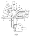
Wie in Fig. 1 dargestellt, tritt ein CO₂-Laserstrahl 1 mit einer Wellenlänge λ = 10,6 µm (oder ein NdYAG-Laserstrahl, λ = 1,06 µm) durch eine Fokussierlinse 2, z.B. aus ZnSe, (plankonvex oder besser mit Positiv-Meniskus) und ein IR-Fenster 3, z.B. aus ZnSe, mit Dichtungsring 4, in eine Kammer 5 ein und trifft (leicht schräg) im Fokus auf eine (durch eine schematisch dargestellte Motor-Programm-Steuerung 6) dreidimensional gesteuerte bewegbare Targetplatte 7 auf. Die Targetplatte kann durch eine Zusatzheizung 8 nach Bedarf zusätzlich aufgeheizt werden. Bei einer Leistungsdichte von 10⁶ bis 10⁷ Watt/cm² im Fokus wird das Targetmaterial dort über den Schmelzpunkt erhitzt, verdampft teilweise, und es bilden sich in der stark übersättigten Dampfphase Partikel 9 bzw. es dampfen Partikel 9 direkt von der Oberfläche ab. Das ZnSe-Fenster 3 wird durch ein inertes Spülgas (Pfeil 10)von eventuellen Aufdampfschichten freigehalten (Einsatz 11 mit Düsen für Spülgas).As shown in Fig. 1, a
Die direkt über dem Auftreffpunkt gebildeten ultrafeinen Partikel 9 werden durch ein inertes Transportgas 31, das durch eine Düse 12 auf die Targetfläche geblasen wird, durch eine geheizte Absaugöffnung (Pfeil 13) zu einer Depositionskammer 14 transportiert und treffen dort auf eine gekühlte Substratelektrode 15 auf (Kühlung 16). Zwischen Substratelektrode 15 und Gegenelektrode 17 kann fakultativ eine Gleichstrom- oder Wechselstrom-Glimmentladung gezündet werden (Spannungsversorgung 18), und es können zusätzlich reaktive Gase für CVD bzw. PCVD in die Depositionskammer 14 eingelassen werden. Transportgase und reaktive Gase bzw. gasförmige Reaktionsprodukte werden von einer Pumpe zu einer Gasentsorgung hin abgesaugt (Pfeil 19), und es wird in der Depositionskammer 14 ein Druck von etwa 1 bis 100 hPa aufrechterhalten, während der Druck in der Verdampferkammer 5 bei etwa 100 bis 1000 hPa liegt (Austrittsdruck in der Gasdüse: einige 10⁵ Pa). Senkrecht zur Auftrefffläche des Laserstrahls wird die Spottemperatur über ein Infrarotpyrometer 20 (Sichtfenster 21) gemessen und z.B. über die Fokuspositionierung nachreguliert. Um einen zeitlich konstanten Partikelfluß zu erzielen und nicht eine starke lokale Änderung der Oberflächengeometrie durch eine unbeabsichtigte Lochbildung zu bekommen, wird das Target 7 kontinuierlich z.B. nach einem Mäanderraster computergesteuert weiterbewegt. Die entstandenen Partikel werden z.B. über einen He-Ne-Laserstrahl 22, der über ein gespültes Fenster 23 (hier Spüleinsatz nicht dargestellt) in die Kammer 5 eintritt und parallel zur Targetplatte 7 über dem erhitzten Fleck (Strahlhöhe über der Platte z.B. verstellbar über eine drehbare planparallele Platte 24 vor dem Fenster 23) geführt wird und durch ein ebenfalls gespültes Sichtfenster 25 auf einen Fotodetektor 26 auftrifft, über Lichtausstreuung und damit Intensitätsminderung des HeNe-Strahls nachgewiesen.The
Der von der Targetoberfläche reflektierte Anteil des CO₂-Laserstrahls wird entweder von einem gekrümmten sphärischen Hohlspiegel 27 auf den Brennfleck zurückreflektiert oder bei stärker streuenden Oberflächen in einem Absorber 28 (z.B. Woodsches Horn) oder "Sumpf" absorbiert. Die Polarisation des IR-Laserstrahls ist zweckmäßigerweise zirkular, um Anisotropien bei der Verdampfung mit linear polarisiertem Strahl zu vermeiden. Es kann jedoch auch ein linear polarisierter Strahl benutzt werden (vergl. Fig. 3), und es können auch andere Einfallswinkel als der in Fig. 1 dargestellte benutzt werden. Auch können Plasmakammer (PCVD, CVD) und Depositionskammer räumlich voneinander getrennt nacheinander angeordnet sein.The portion of the CO₂ laser beam reflected from the target surface is either reflected back onto the focal spot by a curved spherical
Eine Variante der in Fig. 1 dargestellten Anordnung besteht darin, daß die Targetplatte 7 ein runder "Teller" ist, der mit der Winkelgeschwindigkeit um die dort dargestellte Achse 29 drehbar ist, wobei die Achse zusätzlich parallel relativ zum Auftreffpunkt des Laserstrahls linear verschoben werden kann. Der Auftreffpunkt liegt in der Regel exzentrisch.A variant of the arrangement shown in Fig. 1 is that the
Eine weitere Anordnung ist in Fig. 2 dargestellt. Hierbei trifft der NdYAG- oder CO₂-Laserstrahl 1 nicht nahezu senkrecht wie bei Fig. 1 auf, sondern wird in schwach streifendem Einfall im Fokusbereich in eine entsprechend stark verengte Targetdüse 30 fokussiert. Ein inertes (oder reaktives) Transportgas 31 tritt in die Targetkammer 5 ein und strömt durch die Targetdüse 30 in die Depositionskammer 14 aus und transportiert dabei die im (und nach dem) Loch entstehenden Partikel 9 zur Substratoberfläche 15. Der IR-Laserstrahl (oder UV-Laserstrahl) 1 ist dabei zweckmäßigerweise zirkular polarisiert und hat statt eines gaussförmigen oder kastenförmigen radialen Intensitätsprofils vorteilhafterweise ein ring- bzw. "vulkan"förmiges Intensitätsprofil, wie es z.B. beim CO₂-Laser bei leichtem Dejustieren problemlos erzielt werden kann (Fig. 2a, wobei I = Intensität, r = Radius). Dadurch können auch etwas größere Targetkegelöffnungen benutzt werden.Another arrangement is shown in FIG. 2. Here, the NdYAG or
Der flach streifende Einfall hat den Vorteil einer bis zu 50fach höheren elektrischen Feldstärke an der Oberfläche im Vergleich zum senkrechten Einfall, jedoch natürlich den Nachteil der mit dem Einfallswinkel abnehmenden Flächenintensität. Der Targetkegeldüseneinsatz kann über eine in Fig. 2 nicht dargestellte Lineardurchführung - in Dichtringen 4 gleitend - in Strahleinfallsrichtung verschoben werden. Eine Fokus-Verschiebung kann auch durch eine Linearverschiebung der Einfalls-Sammellinse 2 auf der Strahlachse erreicht werden.The flat grazing incidence has the advantage of up to 50 times higher electric field strength on the surface compared to the vertical incidence, but of course the disadvantage of the area intensity decreasing with the angle of incidence. The target cone nozzle insert can be displaced in the beam incidence direction via a linear feedthrough, not shown in FIG. 2 - sliding in sealing rings 4. A focus shift can also be achieved by a linear shift of the converging
Direkt hinter der Kegeldüsenöffnung wird z.B. ein He-Ne Laserstrahl 22 zum Partikelnachweis eingestrahlt, und es wird die Partikelbildung über eine Intensitätsminderung des Strahls registriert. Die Substratelektrode 15, auf die der Partikelstrahl auftrifft, ist mit einer variablen Temperatureinstellung 16 (Kühlung oder Heizung) versehen und kann in allen drei Raumrichtungen linear verschoben werden (Vorrichtung 6'). Eine Gegenelektrode 17 ermöglicht das Anlegen einer Gleich- oder einer Wechselspannung (Spannungsversorgung 18) zwischen dieser und dem Substrat 15 und damit die Ausbildung einer Glimmentladung. Zusätzlich können noch reaktive Gase eingeleitet werden (hier nicht dargestellt), und es können die Partikel per CVD oder PCVD beschichtet oder im Plasma aufgelöst und auf dem Substrat niedergeschlagen werden.For example, a He-
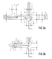
Eine weitere Anordnung ist in Fig. 3a und 3b dargestellt: Das Target 7 ist dabei ein dünnes, linear verschiebbares Metallblech, auf das der CO₂-Laserstrahl 1 im Fokus, leicht geneigt zur Oberflächennormalen, auftrifft, wobei eine Fokusjustierung durch eine Relativverschiebung der ZnSe-Sammellinse (Ge-Sammellinse) 2 in Richtung der Strahlachse erreicht wird. Durch den Winkel zwischen Strahlachse und Targetnormalen von einigen Grad werden Rückreflektionen des Laserstrahls und damit mögliche Leistungsfluktuationen vermieden.A further arrangement is shown in Fig. 3a and 3b: The
Das Strahleintrittsfenster 3 (ZnSe) wird außerdem über einen Spülgas-Düseneinsatz 11 mit inertem Spülgas von innen gespült, um Fensterbeschichtungen zu vermeiden. Das Target 7 ist übrigens im Mittelpunkt eines dreidimensionalen Kreuzstücks 32 angeordnet. Die Brennflecktemperatur wird über ein Pyrometer 20 durch Messung der Temperatur auf der Blechrückseite (an der Brennfleckstelle 33) kontrolliert, und der Fokus wird so in der Regel auf maximale Temperatur nachjustiert. Ein Auffängerblech 34 sitzt in Pumprichtung 19 dem Target 7 gegenüber, deckt in einer erfindungsgemäßen Version fast den gesamten Pumpquerschnitt ab, mit Ausnahme einer zentralen runden Blendenöffnung, hinter der das eigentliche Substrat sitzt. Zusätzlich kann über eine Transportgasdüse 35 auch noch eine Partikelausblasung in Richtung Auffänger erreicht werden.The jet inlet window 3 (ZnSe) is also flushed from the inside with an inert flushing gas via a flushing
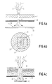
Eine Anordnung zur Einbettung von ultrafeinen Partikeln 9, z.B. aus BaO oder Sc₂O₃ oder SiO₂, in eine z.B. über thermische CVD abgeschiedene Wolfram-Schicht (oder andere Metallschicht) ist in Fig. 4a und 4b dargestellt. Darin ist ein inertes Transportgas, z.B. Argon, durch Pfeile 31 angedeutet. Zwischen einem (x-y) verschiebbaren Target 7, z.B. aus SiO₂, BaO oder Sc₂O₃, und einem geheizten Substrat 15 ist eine ortsfeste Blende 36 mit einer Blendenöffnung 37 für erzwungene Transportgasströmung angeordnet.An arrangement for embedding
Hierbei werden ultrafeine Partikel nicht nur von der Oberfläche des Targets abgedampft, sondern das Target wird vom Laserstrahl total durchbohrt und die kontinuierliche Nachlieferung von ultrafeinen Partikeln erfolgt durch Relativbewegung des Targets senkrecht zum ortsfesten Laserstrahl(-fokus). Die ebenfalls ortsfeste Blende hinter dem Target mit einer Öffnung im Bereich des Laserstrahls bewirkt, daß das inerte Transportgas nur durch diese Öffnung, in der momentan ultrafeine Partikel verdampft werden, und nicht durch die bereits in das Target geschnittenen Spaltöffnungen, in die Reaktions/Sedimentationskammer ausströmt.Here, ultrafine particles are not only evaporated from the surface of the target, but the target is totally pierced by the laser beam and the continuous delivery of ultrafine particles takes place by relative movement of the target perpendicular to the fixed laser beam (focus). The also fixed aperture behind the target with an opening in the area of the laser beam causes the inert transport gas to flow into the reaction / sedimentation chamber only through this opening, in which ultrafine particles are currently being evaporated, and not through the stomata already cut into the target .
Das die ultrafeinen Partikel aus Targetmaterial (z.B. BaO, Sc₂O₃) überführende inerte Transportgas trifft dann auf ein Substrat auf, auf dem aus WF₆ + H₂ (Pfeil 38) Wolfram z.B. über CVD, hier thermische CVD, abgeschieden wird und um die ebenfalls auftreffenden ultrafeinen Partikel herumwächst, so daß eine Materialstruktur aus W mit BaO/Sc₂O₃-Partikeleinbettungen entsteht.The inert transport gas transferring the ultrafine particles of target material (e.g. BaO, Sc₂O₃) then strikes a substrate on which tungsten e.g. from WF₆ + H₂ (arrow 38) is deposited via CVD, here thermal CVD, and grows around the ultrafine particles also striking, so that a material structure of W with BaO / Sc₂O₃ particle embeddings is formed.
Mit einer solchen Anordnung können insbesondere Erdalkali-Nachlieferungskathoden in einem einzigen kontinuierlichen Verfahren hergestellt werden, das die vielen bisherigen Einzelschritte bei der Herstellung, wie Pulverpressen und Sintern zur porösen W-Matrix, Imprägnieren, Aufbringen der Deckschicht, ersetzt. Dadurch werden I-Kathoden für eine Massenproduktion zugänglich.With such an arrangement, in particular alkaline earth replenishment cathodes can be produced in a single continuous process which replaces the many previous individual steps in the production, such as powder pressing and sintering for the porous W matrix, impregnation, application of the cover layer. This makes I-cathodes accessible for mass production.
Die Ausführung ist in Fig. 4c dargestellt: In der Anordnung nach Fig. 4a und 4b wird das Target 7, das übrigens auch direkt lose auf der Blende 36 aufliegen kann, durch ein Target aus vier verschiedenen Schichten ersetzt.The embodiment is shown in FIG. 4c: in the arrangement according to FIGS. 4a and 4b, the
Dabei liegen drei Targetplättchen, jeweils bestehend aus BaO (1 mm dick), CaO (0,5 mm dick) und Al₂O₃ (0,5 mm dick), lose gestapelt aufeinander und werden über zwei Linearführungen z.B. mäanderförmig relativ zum Laserspot verschoben. In der Regel sind diese Targets relativ poröse Preßlinge. Obendrauf befindet sich ein unabhängig von diesen Targets ebenfalls x-y-verschiebbares Sc₂O₃-Plättchen, das erst in der letzten Abscheidungsphase über den Laserspot geschoben wird.There are three target plates, each consisting of BaO (1 mm thick), CaO (0.5 mm thick) and Al₂O₃ (0.5 mm thick), loosely stacked on top of each other and are shifted relative to the laser spot, for example in a meandering shape. As a rule, these targets are relatively porous compacts. On top of that there is an independently xy-displaceable Sc₂O₃ plate, which is only pushed in the last deposition phase over the laser spot.
Anstelle der drei verschiedenen Plättchen aus BaO, CaO und Al₂O₃ kann auch ein Targetpreßling benutzt werden, der aus einer Mischung BaO:CaO:Al₂O₃ im Verhältnis 4:1:1 besteht.Instead of the three different plates made of BaO, CaO and Al₂O₃, a target compact can also be used, which consists of a mixture of BaO: CaO: Al₂O₃ in a ratio of 4: 1: 1.
Es werden nun z.B. folgende Verfahrensparameter eingestellt: Substrattemperatur 500 bis 600°C, WF₆-Fluß 50 sccm, H₂-Fluß 500 sccm, Ar-Fluß 300 sccm, Druck im Depositionskammerteil 14 10 bis 20 hPa, Druck im Bereich 5 des einströmenden Transportgases 100 bis 200 hPa, Laserleistung 50 Watt, Brennweite der fokussierenden Linse 5,2 cm. Bei einer Target-Abtragungsrate von 0,07 g/min und einer W-Abscheidungsrate von etwa 0,3 g/min können schon in einer Beschichtungsdauer von etwa 10 min 1 mm dicke I-Kathodenschichten auf einer Fläche von etwa 1 cm² hergestellt werden. In der letzten Minute der Beschichtungszeit wird dabei zusätzlich das Sc₂O₃-Targetplättchen in den Laserspot verschoben.Now e.g. the following process parameters were set: substrate temperature 500 to 600 ° C, WF₆ flow 50 sccm, H₂ flow 500 sccm, Ar flow 300 sccm, pressure in the
Fakultativ kann die Deckschicht auch mit herausgezogenen 4 BaO.CaO.Al₂O₃-Targets abgeschieden werden.Optionally, the cover layer can also be deposited with 4 BaO.CaO.Al₂O₃ targets pulled out.
Das Substrat wird in der Regel abgelöst, entweder mechanisch oder durch selektives Ätzen oder durch Benutzung eines Substrats, auf dem die W-CVD + Partikeleinbettungsschicht nicht haftet.The substrate is usually peeled off, either mechanically or by selective etching, or by using a substrate on which the W-CVD + particle embedding layer does not adhere.
Fig. 5 zeigt, wie von einem Laserstrahl 1 getroffenes Targetmaterial in Strahlungsrichtung vollständig abgetragen wird, wobei der größte Teil des Strahls mit dem Target in Wechselwirkung tritt und nur ein kleiner Teil 1' am Resttarget 7' vorbeigeht. Es erfolgt also eine Randabtragung, indem der Laserstrahl relativ zum Target in der Targetrandzone am Targetrand entlangbewegt wird (Pfeil 39) und bei geeigneter Einstelllung der Laserparameter wie Leistung, Leistungsdichte sowie der Relativgeschwindigkeit den Targetrand jeweils komplett abträgt. Der bereits abgetragene Targetteil ist mit 7" bezeichnet.FIG. 5 shows how target material struck by a
In den Fig. 6 und 7 sind Verfahrensabläufe bei der chemical vapour infiltration CVI schematisch dargestellt. Aus einem Partikelstrom 40 mit Inertträgergas wird eine Schicht 41 aus ultrafeinen Partikeln (Fig. 6) bzw. aus kettenhaltigen Agglomeraten 41' (Fig. 7) auf bzw. an einem porösen Substrat 15' abgelagert. Die Schichten 41 bzw. 41' und die porösen Substrate 15' werden von einem reaktiven Gas, z.B. WF₆/H₂, durchströmt (Pfeile 38). 42 bedeutet eine ohmsche Heizwicklung und 43 eine Spule für induktive Heizung.6 and 7, process sequences for chemical vapor infiltration CVI are shown schematically. A
In Fig. 7 können folgende Materialströme vertauscht werden: 19 gegen 38 bei Umkehrung der Richtung; 38 gegen 40; 40 gegen 19 bei Umkehrung der Richtung.The following material flows can be exchanged in FIG. 7: 19 against 38 when the direction is reversed; 38 against 40; 40 versus 19 reversing direction.
Auch kann die Abscheidung von Agglomeraten ultrafeiner Partikel und die CVI-Verfestigung nacheinander durchgeführt werden.The separation of agglomerates of ultrafine particles and the CVI solidification can also be carried out in succession.
Claims (21)
dadurch gekennzeichnet, daß die ultrafeinen Partikel beim Beschichten des Substrats zusammen mit einer weiteren Materialkomponente aufgebracht werden, wobei diese Komponente durch reaktive Abscheidung aus einer zusätzlichen Gasphase, d.h. durch CVD, plasma-aktivierte CVD oder laserinduzierte CVD, mit aufgebracht wird.Process for the production of multi-component solid materials, whereby a substrate is coated with ultrafine particles,
characterized in that the ultrafine particles are applied together with a further material component during coating of the substrate, this component being applied by reactive deposition from an additional gas phase, ie by CVD, plasma-activated CVD or laser-induced CVD.
dadurch gekennzeichnet, daß zuerst die ultrafeinen Partikel aufgebracht werden und anschließend eine Verfestigung mit Hilfe von CVI = chemical vapour infiltration erfolgt.Process for the production of multi-component solid materials, whereby a substrate is coated with ultrafine particles,
characterized in that first the ultrafine particles are applied and followed by a solidification by means of CVI = c hemical v apour i nfiltration.
dadurch gekennzeichnet, daß die Substrate mit ultrafeinen Partikeln aus mehreren Materialien beschichtet werden, wobei die einzelnen ultrafeinen Partikel entweder nur aus einem Material oder aus mehreren Materialien bestehen und die Partikel anschließend durch eine Wärmebehandlung gesintert und damit porös kompaktiert werden.Process for the production of multi-component solid materials, whereby a substrate is coated with ultrafine particles,
characterized in that the substrates are coated with ultrafine particles made of several materials, the individual ultrafine particles either consisting of only one material or of several materials and the particles are then sintered by a heat treatment and thus compacted porously.
dadurch gekennzeichnet, daß die ultrafeinen Partikel ohne zusätzliche Verfestigung in Form von auf der Substratoberfläche fest haftenden vernetzten Kettenstrukturen und Kettenenden aufgebracht werden.The method of claim 1, 2 or 3,
characterized in that the ultrafine particles are applied without additional solidification in the form of crosslinked chain structures and chain ends adhering firmly to the substrate surface.
dadurch gekennzeichnet, daß das Target aus 4BaO . CaO . Al₂O₃ zusammengesetzt wird, in der letzten Beschichtungsphase ultrafeine Partikel aus einem weiteren Target aus Sc₂O₃ verdampft werden und die weitere Materialkomponente zum Verfestigen der porösen Struktur Wolfram ist, das über PCVD, CVD oder CVI aus WF₆/H₂ oder einer anderen gasförmigen W-Quelle abgeschieden wird.The method of claim 1, 2 or 3,
characterized in that the target from 4BaO. CaO. Al₂O₃ is composed, in the last coating phase ultrafine particles are evaporated from another target made of Sc₂O₃ and the other material component for solidifying the porous structure is tungsten, which is deposited from PCVD, CVD or CVI from WF₆ / H₂ or another gaseous W source .
dadurch gekennzeichnet, daß die ultrafeinen Partikel durch Laserstrahlverdampfung aus einem Target erzeugt werden, wobei der Laserstrahl derart auf das Target gerichtet wird, daß die Abtragung des Targetmaterials in gleichlaufender Richtung wie der Laserstrahl erfolgt.The method of claim 1, 2, 3, 4 or 5,
characterized in that the ultrafine particles are generated by laser beam evaporation from a target, the laser beam being directed onto the target in such a way that the removal of the target material takes place in the same direction as the laser beam.
dadurch gekennzeichnet, daß die abdampfenden ultrafeinen Partikel durch ein Loch im Target hindurch und gegebenenfalls noch durch eine zusätzliche Blende abströmen.Method according to claim 6,
characterized in that the evaporating ultra-fine particles flow out through a hole in the target and optionally through an additional orifice.
dadurch gekennzeichnet, daß die Oberfläche des Targets vor Beginn der Abtragung aufgerauht, geschmirgelt oder oxidiert wird.Method according to claim 6 or 7,
characterized in that the surface of the target is roughened, sanded or oxidized before the removal begins.
dadurch gekennzeichnet, daß als Target ein poröser Preßling verwendet wird.Method according to claim 6 or 7,
characterized in that a porous compact is used as the target.
dadurch gekennzeichnet, daß verschiedene Materialkomponenten gleichzeitig verdampft und ultrafeine Partikel daraus erzeugt werden.The method of claim 6, 7, 8 or 9,
characterized in that different material components evaporate simultaneously and ultrafine particles are generated therefrom.
dadurch gekennzeichnet, daß das Target direkt oder indirekt aufgeheizt wird.Method according to one or more of claims 6 to 10,
characterized in that the target is heated directly or indirectly.
dadurch gekennzeichnet, daß die Laserstrahlverdampfung aus dem Target vor, im oder hinter dem Fokus eines fokussierten Strahls erfolgt.Method according to one or more of claims 6 to 11,
characterized in that the laser beam evaporation from the target occurs before, in or behind the focus of a focused beam.
dadurch gekennzeichnet, daß die Fokussierung in oder außerhalb einer Targetkammer durch einen sphärischen fokussierenden Spiegel, der mit Inertgas gespült wird, erfolgt.Method according to claim 12,
characterized in that the focusing takes place in or outside a target chamber by means of a spherical focusing mirror which is flushed with inert gas.
dadurch gekennzeichnet, daß der Laserstrahl ein Leistungsprofil auf der Targetoberfläche aufweist, das aus einem schmalen Abtragbereich mit hoher Leistung und einem breiteren Heizbereich mit niedrigerer Leistung besteht.Method according to one or more of claims 6 to 13,
characterized in that the laser beam has a power profile on the target surface, which consists of a narrow removal area with high power and a wider heating area with lower power.
dadurch gekennzeichnet, daß die ultrafeinen Partikel über ein in der Regel inertes Transportgas und eine gegebenenfalls zwischengeschaltete Größenselektion zu einem Substrat überführt werden.Method according to one or more of claims 6 to 14,
characterized in that the ultrafine particles are transferred to a substrate via a generally inert transport gas and, if appropriate, an intermediate size selection.
dadurch gekennzeichnet, daß den ultrafeinen Partikeln eine Größenverteilung mit einer Standardabweichung von höchstens 10% des mittleren Durchmessers erteilt wird oder daß nur selektierte Partikel dieser Größenverteilung inclusive deren Agglomerate zum Substrat gelangen.Method according to one or more of claims 6 to 15,
characterized in that the ultrafine particles are given a size distribution with a standard deviation of at most 10% of the mean diameter or that only selected particles of this size distribution including their agglomerates reach the substrate.
dadurch gekennzeichnet, daß eine Dosierung der ultrafeinen Partikel durch Einstellung der Laserleistungsdichte auf der Targetauftrefffläche, der Größe des Auftreffflecks, der Relativgeschwindigkeit zwischen Target und Laserstrahl, des Gesamtdrucks in der Targetkammer und/oder eine Aufteilung des Trägergasstromes erfolgt.Method according to one or more of claims 6 to 16,
characterized in that the ultrafine particles are metered by adjusting the laser power density on the target impact surface, the size of the impact spot, the relative speed between the target and the laser beam, the total pressure in the target chamber and / or a division of the carrier gas flow.
dadurch gekennzeichnet, daß die genannten Größen während der Verfahrensdauer konstant gehalten werden.The method of claim 17
characterized in that the quantities mentioned are kept constant during the duration of the process.
dadurch gekennzeichnet, daß der Gesamtdruck in der Targetkammer so niedrig eingestellt wird, daß das Maximum der Größenverteilung mit der zu selektierenden Partikelgröße zusammenfällt.Method according to claim 17 or 18,
characterized in that the total pressure in the target chamber is set so low that the maximum of the size distribution coincides with the particle size to be selected.
dadurch gekennzeichnet, daß die ultrafeinen Partikel mit Ladungen gleichen Vorzeichens aufgeladen werden und im Fall von oxidischen Partikeln bzw. Isolatoren vorzugsweise mit einer dünnen, nur einige Monolagen dicken elektrisch leitenden bzw. metallischen Oberflächenschicht vorher überzogen werden.Method according to one or more of claims 6 to 19,
characterized in that the ultrafine particles are charged with charges of the same sign and, in the case of oxidic particles or insulators, are preferably coated beforehand with a thin, only a few monolayers thick electrically conductive or metallic surface layer.
dadurch gekennzeichnet, daß die die ultrafeinen Partikel umhüllende Materialkomponente ein Material mi in dem Partikel-Material vernachlässigbarer fester Löslichkeit ist.A method according to claim 20,
characterized in that the material component enveloping the ultrafine particles is a material mi in the particle material negligible solid solubility.
Applications Claiming Priority (2)
| Application Number | Priority Date | Filing Date | Title |
|---|---|---|---|
| DE4000739 | 1990-01-12 | ||
| DE19904000739 DE4000739A1 (en) | 1990-01-12 | 1990-01-12 | METHOD FOR PRODUCING MULTI-COMPONENT MATERIALS |
Publications (1)
| Publication Number | Publication Date |
|---|---|
| EP0437890A1 true EP0437890A1 (en) | 1991-07-24 |
Family
ID=6397957
Family Applications (1)
| Application Number | Title | Priority Date | Filing Date |
|---|---|---|---|
| EP90203468A Withdrawn EP0437890A1 (en) | 1990-01-12 | 1990-12-21 | Method for production of multicomponent materials |
Country Status (3)
| Country | Link |
|---|---|
| EP (1) | EP0437890A1 (en) |
| JP (1) | JPH04214860A (en) |
| DE (1) | DE4000739A1 (en) |
Cited By (7)
| Publication number | Priority date | Publication date | Assignee | Title |
|---|---|---|---|---|
| WO2000012775A1 (en) * | 1998-08-26 | 2000-03-09 | Fraunhofer-Gesellschaft zur Förderung der angewandten Forschung e.V. | Method and device for coating substrates in a vacuum |
| US6533908B1 (en) | 1998-08-26 | 2003-03-18 | Fraunhofer-Gesellschaft Zur Forderung Der Angewandten Forschung E.V. | Device and method for coating substrates in a vacuum utilizing an absorber electrode |
| CN109702344A (en) * | 2019-01-25 | 2019-05-03 | 大连理工大学 | Hot arc and laser composite heat power supply evaporate Multicarity nano powder preparing device |
| CN109702215A (en) * | 2019-01-25 | 2019-05-03 | 大连理工大学 | Hot arc evaporates Multicarity nano powder preparing device |
| CN109759600A (en) * | 2019-01-25 | 2019-05-17 | 大连理工大学 | Laser evaporation Multicarity nano powder preparing device |
| WO2023006197A1 (en) * | 2021-07-28 | 2023-02-02 | MAX-PLANCK-Gesellschaft zur Förderung der Wissenschaften e.V. | Method of coating a coating region on a front surface of a substrate and apparatus for a thermal evaporation system |
| CN117359992A (en) * | 2023-12-04 | 2024-01-09 | 山西炭科新材科技股份有限公司 | Forming device is used in production of column active carbon |
Families Citing this family (1)
| Publication number | Priority date | Publication date | Assignee | Title |
|---|---|---|---|---|
| KR100806113B1 (en) * | 2006-12-26 | 2008-02-21 | 주식회사 코윈디에스티 | Metal gas supply apparatus and remaining gas removal apparatus used for thin film depositing apparatus and method thereof |
Citations (4)
| Publication number | Priority date | Publication date | Assignee | Title |
|---|---|---|---|---|
| EP0143122A2 (en) * | 1983-08-26 | 1985-06-05 | Shin-Etsu Chemical Co., Ltd. | An ultrafine powder of silcon carbide, a method for the preparation thereof and a sintered body therefrom |
| JPS60116705A (en) * | 1983-11-30 | 1985-06-24 | Hitachi Ltd | Manufacture apparatus of ultrafine metallic powder |
| JPS6173881A (en) * | 1984-09-19 | 1986-04-16 | Fuji Electric Co Ltd | Vapor growth device |
| DE3800680A1 (en) * | 1988-01-13 | 1989-07-27 | Leyendecker Toni | Process and appliance for coating a substrate |
-
1990
- 1990-01-12 DE DE19904000739 patent/DE4000739A1/en not_active Withdrawn
- 1990-12-21 EP EP90203468A patent/EP0437890A1/en not_active Withdrawn
-
1991
- 1991-01-14 JP JP1610391A patent/JPH04214860A/en active Pending
Patent Citations (4)
| Publication number | Priority date | Publication date | Assignee | Title |
|---|---|---|---|---|
| EP0143122A2 (en) * | 1983-08-26 | 1985-06-05 | Shin-Etsu Chemical Co., Ltd. | An ultrafine powder of silcon carbide, a method for the preparation thereof and a sintered body therefrom |
| JPS60116705A (en) * | 1983-11-30 | 1985-06-24 | Hitachi Ltd | Manufacture apparatus of ultrafine metallic powder |
| JPS6173881A (en) * | 1984-09-19 | 1986-04-16 | Fuji Electric Co Ltd | Vapor growth device |
| DE3800680A1 (en) * | 1988-01-13 | 1989-07-27 | Leyendecker Toni | Process and appliance for coating a substrate |
Non-Patent Citations (4)
| Title |
|---|
| EXTENDED ABSTRACTS/ELECTROCHEMICAL SOCIETY, Band 87-2, 18. Oktober 1987, Seiten 1545-1546; D.P. STINTON: "Ceramic composites by chemical vapor infiltration" * |
| JOURNAL OF APPLIED PHYSICS, Band 66, Nr. 7, Oktober 1989, Seiten 3304-3308; G.-M. CHOW et al.: "Nanometer-size fiber composite synthesis by laser-inducec reactions" * |
| PATENT ABSTRACTS OF JAPAN, Band 10, Nr. 245 (C-368)[2301], 22. August 1986; & JP-A-61 73 881 (FUJI) 16-04-1986 * |
| PATENT ABSTRACTS OF JAPAN, Band 9, Nr. 272 (M-425)[1995], 30. Oktober 1985; & JP-A-60 116 705 (HITACHI SEISAKUSHO) 24-06-1985 * |
Cited By (12)
| Publication number | Priority date | Publication date | Assignee | Title |
|---|---|---|---|---|
| WO2000012775A1 (en) * | 1998-08-26 | 2000-03-09 | Fraunhofer-Gesellschaft zur Förderung der angewandten Forschung e.V. | Method and device for coating substrates in a vacuum |
| US6533908B1 (en) | 1998-08-26 | 2003-03-18 | Fraunhofer-Gesellschaft Zur Forderung Der Angewandten Forschung E.V. | Device and method for coating substrates in a vacuum utilizing an absorber electrode |
| US6558757B1 (en) | 1998-08-26 | 2003-05-06 | Fraunhofer-Gesellschaft Zur Forderung Der Angewandten Forschung E.V. | Method and device for coating substrates in a vacuum |
| CN109702344A (en) * | 2019-01-25 | 2019-05-03 | 大连理工大学 | Hot arc and laser composite heat power supply evaporate Multicarity nano powder preparing device |
| CN109702215A (en) * | 2019-01-25 | 2019-05-03 | 大连理工大学 | Hot arc evaporates Multicarity nano powder preparing device |
| CN109759600A (en) * | 2019-01-25 | 2019-05-17 | 大连理工大学 | Laser evaporation Multicarity nano powder preparing device |
| CN109702344B (en) * | 2019-01-25 | 2023-12-29 | 大连理工大学 | Thermal arc and laser composite heat source evaporation multi-cavity nano powder preparation device |
| CN109702215B (en) * | 2019-01-25 | 2023-12-29 | 大连理工大学 | Thermal arc evaporation multi-cavity nano powder preparation device |
| CN109759600B (en) * | 2019-01-25 | 2024-02-06 | 大连理工大学 | Laser evaporation multi-cavity nano powder preparation device |
| WO2023006197A1 (en) * | 2021-07-28 | 2023-02-02 | MAX-PLANCK-Gesellschaft zur Förderung der Wissenschaften e.V. | Method of coating a coating region on a front surface of a substrate and apparatus for a thermal evaporation system |
| CN117359992A (en) * | 2023-12-04 | 2024-01-09 | 山西炭科新材科技股份有限公司 | Forming device is used in production of column active carbon |
| CN117359992B (en) * | 2023-12-04 | 2024-03-05 | 山西炭科新材科技股份有限公司 | Forming device is used in production of column active carbon |
Also Published As
| Publication number | Publication date |
|---|---|
| JPH04214860A (en) | 1992-08-05 |
| DE4000739A1 (en) | 1991-07-18 |
Similar Documents
| Publication | Publication Date | Title |
|---|---|---|
| EP0442163B1 (en) | Method for production of ultrafine particles and their use | |
| EP0535019B1 (en) | Process and device for coating substrate material | |
| DE4217450C2 (en) | Ion vapor deposition method and device | |
| DE69407734T2 (en) | Process for the production of diamond-like coatings | |
| EP0306612B1 (en) | Process for depositing layers on substrates | |
| DE4340752C2 (en) | Device for producing a uniform thin film on a large substrate area using a laser | |
| DE69602131T2 (en) | System for electron beam deposition from the gas phase | |
| DE3854307T2 (en) | Hollow cathode cannon and device for material deposition by ion coating. | |
| DE3611492A1 (en) | METHOD AND DEVICE FOR COATING TOOLS FOR CUTTING AND FORMING TECHNOLOGY WITH PLASTIC LAYERS | |
| EP0727508A1 (en) | Method and apparatus for treatment of substrate surfaces | |
| DE2006075A1 (en) | Method and device for the production of fine powders of a metal or an alloy | |
| DE4016352A1 (en) | LASER EVAPORATION DEVICE | |
| EP0437890A1 (en) | Method for production of multicomponent materials | |
| DE3785295T2 (en) | METHOD FOR PRODUCING A FILM FROM ULTRAFINE PARTICLES. | |
| EP1558782A2 (en) | Device and method for the evaporative deposition of a high-temperature superconductor in a vacuum with continuous material introduction | |
| EP0438627B1 (en) | Arc-evaporator with several evaporation crucibles | |
| DE3800680A1 (en) | Process and appliance for coating a substrate | |
| DE3925085C1 (en) | ||
| EP0425623A1 (en) | Process for applying ceramic material. | |
| DE69314770T2 (en) | Reactive deposition process using an ionized cluster beam | |
| DE4006456C1 (en) | Appts. for vaporising material in vacuum - has electron beam gun or laser guided by electromagnet to form cloud or pre-melted spot on the target surface | |
| DE4408052C1 (en) | Use of an apparatus for cluster beam production and for surface coating of a substrate | |
| EP0444538A2 (en) | Device and procedure for vacuum evaporation of a material and utilisation of the procedure | |
| DE19538110A1 (en) | Process for formation of thin diamond-like carbon@ layers on a substrate | |
| DE4035073C1 (en) |
Legal Events
| Date | Code | Title | Description |
|---|---|---|---|
| PUAI | Public reference made under article 153(3) epc to a published international application that has entered the european phase |
Free format text: ORIGINAL CODE: 0009012 |
|
| AK | Designated contracting states |
Kind code of ref document: A1 Designated state(s): DE FR GB |
|
| STAA | Information on the status of an ep patent application or granted ep patent |
Free format text: STATUS: THE APPLICATION IS DEEMED TO BE WITHDRAWN |
|
| 18D | Application deemed to be withdrawn |
Effective date: 19920325 |