EP0437780B1 - Front body structure of a vehicle - Google Patents
Front body structure of a vehicle Download PDFInfo
- Publication number
- EP0437780B1 EP0437780B1 EP19900124792 EP90124792A EP0437780B1 EP 0437780 B1 EP0437780 B1 EP 0437780B1 EP 19900124792 EP19900124792 EP 19900124792 EP 90124792 A EP90124792 A EP 90124792A EP 0437780 B1 EP0437780 B1 EP 0437780B1
- Authority
- EP
- European Patent Office
- Prior art keywords
- nose unit
- vehicle body
- unit
- shroud
- mounting
- Prior art date
- Legal status (The legal status is an assumption and is not a legal conclusion. Google has not performed a legal analysis and makes no representation as to the accuracy of the status listed.)
- Expired - Lifetime
Links
Images


Classifications
-
- B—PERFORMING OPERATIONS; TRANSPORTING
- B62—LAND VEHICLES FOR TRAVELLING OTHERWISE THAN ON RAILS
- B62D—MOTOR VEHICLES; TRAILERS
- B62D25/00—Superstructure or monocoque structure sub-units; Parts or details thereof not otherwise provided for
- B62D25/08—Front or rear portions
- B62D25/082—Engine compartments
- B62D25/084—Radiator supports
Definitions
- This invention relates to a front body structure of a vehicle, wherein a nose unit having at least a shroud panel and a shroud upper is mounted to a front part of a vehicle body.
- JP-A-63103771 on which the preamble of claim 1 is based proposes to incorporate components, such as a radiator, head lamps, a bumper and a radiator grille, to one unit by fitting them to a radiator core support and mount this unit to a front part of a vehicle body.
- both ends bi of the shroud upper b which forms mounting portion for the unit to the vehicle body (wheel apron reinforcement a) at inserting a unit may interfere with the front end portion C1 of the front fender positioned in the inner side of the vehicle body.
- the vertical line I designates an inserting line of the unit and the dotted line P designates a mounting position of the unit.
- the object of the present invention is to provide a front body structure of a vehicle where a nose unit is mounted to a front part thereof without interfering with the front fenders that are already mounted to the vehicle body,
- the front vehicle body of the present invention comprises the structure according to the features of claim 1.
- the dependent claims 2 to 6 further embodiments of the invention are defined.
- reference numeral 1 designates a vehicle having a nose unit 3 which is mounted on the front part of a vehicle body 2.
- Front fenders 4 are provided on both sides of the body 2, and a bonnet 5 is provided on the front top of the vehicle body 2.
- front sideframes 13 are connected to the vehicle body under wheel aprons 12 forming right and left side walls of an engine room 11 and a wheel apron reinforcement 14 are connected to the vehicle body above the wheel aprons 12 so that both top and bottom closed sectional constructions extending longitudinally of the vehicle body are formed.
- Bracket 15 projecting to the inner side of the vehicle body is provided around each wheel apron reinforcement 14.
- Each bracket 15, as shown in Fig. 3, comprises a base part 15a fitted to the adjacent wheel reinforcement 14 and a mounting portion 15b extending inboard from the base part 15a.
- a fitting portion 22b of a shroud upper 22 of nose unit 3 is mounted to the mounting portion 15b.
- Two nuts 16 are welded on the underside of the mounting part 15b.
- Other brackets 17 are provided on the front top ends of the front sideframes 13.
- Mounting flange portions 12a, 12b, 12c are formed on the front end portion of each wheel apron 12. Nuts 18 for fixing a shroud panel 21 by bolts 20 are welded on the undersurface of the flange portions 12a, 12b. A nut 37 for fixing the shroud panel 21 and a junction panel 31 by a bolt 34 are welded on the undersurface of each flange portion 12c.
- front end panels 19 are provided on the front end portion of the wheel aprons 12.
- the nose unit 3 is constructed as illustrated in detail in Figs.4 and 5.
- the unit base of the nose unit 3 is connected to the shroud upper 22 extending in the widthwise direction of the vehicle body on the upper end portions of the shroud panels 21 as shown in Fig.6.
- This shroud upper 22 comprises a vertical wall part 22A extending vertically and an upper wall part 22B extending rearwardly from the upper end of the vertical wall part 22A.
- a pair of vertical members 23 are hanging down from a center part in the widthwise direction of the upper wall part 22B.
- a cross member 26 of a closed sectional construction which is formed by contacting an upper member 26A with a lower member 26B, is provided on the both lower ends of the vertical members 23.
- An opening 21 a for later described lump units 61A, 61B is provided on the shroud panel 21, however, the opening can be a cutaway part 21 b instead of an opening as shown in Fig.7.
- supporting brackets 27 for supporting a condenser 24A and a radiator 24B both of which are weight members are provided on the rear side
- supporting brackets 28 for supporting an intercooler 51 are provided on the front side.
- the condenser 24A and the radiator 24B are connected integrally by a member (not shown in the drawings) the lower end portions thereof being supported by supporting brackets 27 through rubber mount members, and the upper end portions thereof being fixed to fitting holes 21 a of an upper wall part 22B of the shroud upper 22 by tightening bolts 33 through brackets 30.
- reference numeral 29 designates a pulling hook fixed to the underside of the junction panel 31.
- each junction panel 31 of square cylindrical configuration is mounted to the shroud panel 21.
- a rear end flange portion 31 a of the junction panel 31 is positioned to the rear side of the shroud panel 21.
- the junction panel 31 and a front sideframe are clamped coaxially by the front sideframe 13 (a nut 36 welded on the rear surface of the bracket 17) and a wheel apron 12 (nuts 37 welded or the rear surface of a the flange portion 12c) through a junction plate 32 of flat plate configuration.
- Bolts 43 provided on a bumper reinforcement 42 where a bumper 41 is mounted to are fixed to a front end flange portion 31 b of each junction panel 31.
- the both ends of the bumper 41 are also fixed to a mounting portion 4a of each front fender 4 of the vehicle body 2 by bolts 45 provided on the bumper 41 and bolts (not shown in the drawings) passing through a fitting hole 41 a of the bumper 41.
- Both ends 22b of the upper wall parts 22B of the shroud upper 22 are overlapped on brackets 15 and are clamped to brackets 15 by bolts (only two bolts 36 of one mounting portion 22b are shown in Fig.5).
- intercooler 51 An upper part of intercooler 51 is clamped to the vertical wall part 22A of the shroud upper 22 by bolts 53 through brackets 52.
- a radiator grille 54 is positioned at the front center part of the vehicle, both right and left mounting portions 54a thereof being fitted into fitting holes of the vertical wall parts 22A of the shroud upper 22.
- a center mounting portion 54b is fitted into a fitting hole of a vertical member 56 of bonnet lock means 55.
- Reference numerals 61A, 61 B are right and left lamp units, mounting portions 61 a on the upper end of each unit are clamped to the vertical wall part 22A of the shroud upper 22 by bolts 62, and mounting portions 61 b on the lower end of each unit are clamped to the shroud panel 21 by bolts 63 (only bolts 62, 63 and 61 b for the lamp unit 61 A are illustrated in the drawing).
- Reference numerals 64, 65 are harness for connecting the electric system and are clamped to the support member 26 by fastening bolts 67 into a mounting portion 66 and fitted into a fitting hole of the upper wall part 22B of the shroud upper 22 through mounting portions 68 respectively.
- Reference numerals 71 designate shock absorber members for the shock at opening/closing the bonnet 5 and connected to an upper wall part 22B of the shroud upper 22.
- the nose unit 3 Since the mounting portions 15b(mounting portions for the shroud upper) of the brackets 15 for the wheel reinforcement 14 are projecting to the inner side of the vehicle body with respect to the fixing portion for the front fenders 4 when the nose unit 3 is inserted to the vehicle body 2 from the front, the nose unit 3 won't interfere with the front fenders 4 of the vehicle body 2 and it is positioned by overlapping a fixing portion 22b on both ends of the shroud upper 22 of the nose unit 3 with the mounting portions 15b of brackets 15 of the wheel reinforcements 14.
- the nose unit 3 (a shroud upper 22) is fixed to the vehicle body 2.
- each bracket 15 is separate from its adjacent wheel reinforcement 14, however, it can be integrally formed with the wheel reinforcement 14 or with a wheel apron 12.
- bracket 15 is fixed to the wheel apron reinforcement 14, however, as shown in Figs.9-11, a bracket 81 having a hollow could be used which is fixed on the engine room side of the wheel apron 12 and on further inner and lower than a mounting portion 4b of the vehicle body 2 of the front fender 4 so that a fixing portion 82a of a shroud upper 82 is clamped to an upper surface 81 a of the bracket 81 by bolts 85.
- the bracket 81 comprises a flange portion 81 b on its periphery, the flange portion may be fixed to the front end flange portion 12d and an inner surface 12e of the wheel apron 12 by being welded or may be connected to a wheel apron reinforcement 83.
- Reference numeral 84 designates a cross member for connecting right and left front side frames 3.
- a bracket 111 for supporting the shroud upper 110 can be not fixed to both the vehicle body 2 and the shroud upper 110.
- a first fixing portion is constructed by clamping a bracket 111 to the front fender 4, which is done by fastening a bolt 113 wherein a base part of the bracket 111 is overlapped on the under side of the front fender 4. Then the front fender 4, where the base part of the bracket 111 is fixed to, and a bracket 111 are overlapped on the top of the wheel apron 12 so that a second fixing portion is formed by clamping them by a bolt 115 and a nut 114. Through this, the bracket 111 is fixed to the wheel apron 12 (the vehicle body 2) together when the front fender 4 is fixed to the wheel apron 12.
- the nose unit 3 is inserted and determines the position of it and a fixing portion 22b for the shroud upper 22 is clamped to the bracket 111 by a bolt 116.
- a bolt 116 When the front fender 4 is replaced, it can be removed by untightening bolts 113, 115.
- the support member for supporting the heavyweight member such as a radiator comprises one member extending in the widthwise direction of the vehicle body, however, it may comprise two support members 128 being spaced with a fixed distance in the widthwise direction.
- the components are fitted to a nose unit 121 wherein a nose base 121 is put on a jig 122 for mounting the nose unit.
- the jig 122 for mounting the nose unit comprises a base part 122a extending in the widthwise direction of the vehicle body, vertical arm parts 122b, 122c extending upwardly from both ends of the base part 122a, and arm parts 122d, 122e extending inwardly from the upper ends of the arm parts 122d, 122e.
- On the base part 122a three engaging pins 124A, 124B, 124C are provided upwardly projecting, but moving in the vertical direction, and on the arm parts 122d, 122e, two engaging pins 124D, 124E are provided downwardly projecting, but moving in the vertical direction.
- the engaging pins 124A-124E move vertically by cylinders (only cylinders 181 D, 181 E for the engaging pins 124D, 124E are shown in the drawing).
- a unit base 123 comprises right and left shroud panels 125, a shroud upper 126 extending in the widthwise direction of the vehicle body and fixed to the upper end of the shroud panels 125, a center steer 127 hanging down from the mid-position of the shroud upper 126 in the widthwise direction of the vehicle body, and first and second support members 128 each fixed to the lower end portion of each shroud panel 125.
- the shroud upper 126 comprises a vertical wall part 126A extending vertically, an upper wall part 126B extending rearwardly from the upper end of the vertical wall part 126A, and a rear wall part 126C extending downwardly from the rear end of the upper wall part 126B (Fig.21).
- the center steer 127 extending in the vertical direction of the vehicle body is hanging down from the midposition of the vertical wall part 126A in the widthwise direction of the vehicle body.
- Each support member 128 comprises an upper wall part 128a for supporting a lower part of a radiator 129 which is a heavyweight member, a vertical wall part 128b extending downwardly from the front end of the upper wall part 128a and contacts the shroud side panel 125, and a support part 128c for supporting a cooler condenser 130 which is a heavyweight member and projects to the front from the lower end of the vertical wall part 128b.
- an engaging part comprising fitting holes 126a, 126b, 127a, 128d, 128d for detacheably connecting with the engaging pins 124D, 124E, 124B, 124A, 124C are formed.
- the position of the nose unit 121 is determined by the relationship between the engaging pins 124D, 124E, 124B, 124A, 124C and the fitting holes 126a, 126b,127a,128d,128d.
- a lower end portion of a radiator 129 and the cooler condensor 130 is supported by upper wall parts 128a of the support members 128 (fitting holes 128e) and support parts 128c (fitting holes) through rubber mounts 131 A, 131B.
- the upper end portion of the radiator 129 and the cooler condenser 130 are clamped to the upper wall part 126B (fitting holes) of the shroud upper 126 reinforced by a radiator reinforcement 133 (refer to Fig. 23) and a vertical wall part 126A by bolts 134A, 134B through brackets 132A, 132B respectively.
- reference numeral 157 designates a nut for screwed on the bolt 134A which is already welded on the underside of an upper wall part 126B of the shroud upper 126 through the radiator reinforcement 133.
- Mounting portions 125a are formed around the lower end portion of the shroud panel 125 so that two inner bolts 137A out of four-in-a-set bolts disposed on the bumper reinforcement 136, which a bumper face 135 is mounted to, are fixed to the mounting portions 125a as a temporarily mounting for forming a unit by using a nut 142.
- the other outer two bolts 137B are fixed to a front flange part 139a of a frame outer 139A of a front frame 139 through side part 138a of a cross member 138 when mounting a nose unit 121 to a front part of a vehicle so that the bumper reinforcement 136 is connected to the vehicle body 2 directly (Fig.20).
- Both ends of the upper wall part 126B of the shroud upper 126 are clamped to a shroud bracket 141 by bolts 140.
- a base part of this shroud bracket 141 is clamped between the wheel apron reinforcement 14 and the front fender 4 by a bolt 143 and a nut 144.
- the support member 128 is mounted by the cross member 138 wherein the nose unit 121 is installed in the front part of the vehicle body 2 and fixed to a front wall part and an upper wall part of an upper member 138A of the cross member 138 by bolts 147, 148 and nuts 145, 146 through seven fitting holes of an upper wall part 128a and a front wall part 128b of the support member 128 (Fig.21).
- Reference numeral 151 designates a cooler receiver, the side part thereof is clamped to the center steer 127 by bolts 153 through bracket 152.
- a joint metal fitting 155 of a horse member 154 from a cooler receiver 151 is connected to a joint metal fitting of a horse member 155A of the cooler condenser 130.
- Reference numeral 161 designates bonnet lock means clamped to a vertical wall part 126A of the shroud upper 126 by bolts 162 through the center steer 127.
- Reference numeral 163 designates a power steering pipe clamped to a center steer 127 and one of the shroud panels 125 through a mounting implement 164 and bolts 165.
- Reference numerals 166 designate horn members fixed to the center steer 127 by a bolt 167.
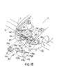
- Right and left lamp units 172 comprising a radiator grille 171, a head lamp 172A, and a front combination lamp 172B, those positioned front center part of the vehicle, are mounted to the nose unit and the vehicle body after the nose unit 121 is mounted to the vehicle body as shown in Fig.18, this step differs from the first embodiment.
- the radiator grille 171 comprises engaging parts 171a, 171b, 171c, having right and left side engaging parts 171a, 171c connected detacheably to a vertical wall part 126A (a fitting hole) of the shroud upper 126 and a center engaging part 171 b connected detacheably to a vertical wall part 126A (a fitting hole) of the shroud upper 126 through bonnet lock means 161.
- mounting portions 172a, 172b on the head lamp 172A side are clamped to a side end portion of the shroud panel 125 and un upper wall part 126B (a fitting hole) of the shroud upper 126 by bolts 182, 183 respectively, and an engaging portion 172c on the front combination lamp 172B side is fitted into an engaging portion 184 of the wheel apron.
- the components are mounted to the unit base wherein the unit base 123 is supported by the jig 122 for mounting the nose unit and also positioned the relationship between the engaging pins 124A-124E and the fitting holes 126a, 126b 127a, 128d, 128d (Fig.16).
- the nose unit 121 is put on a truck 173 with the jig 122 and mounted to the front part of the vehicle body 2 moving on an assembling line S (a main line).
- an assembling line S a main line.
- engaging projecting parts 174a of a deformation preventing tool 174 for preventing the deformation is detacheably engaged with engaging portions 2A of both right and left sides of the vehicle body 2, engaging portions 2A and the deformation preventing tool 174 can be excluded since the cross member 138 has an effect for preventing a deformation of the front part of a vehicle.
- the center steer 127 and the support member 128 are clamped to the cross member 138 by tightening the bolt 147 into a nut 146 through fastener 175, 176 using a bolt 148 and a nut 145.
- the bumper reinforcement 136 is clamped to a side part 138a of the cross member 138 by screwing a nut 149 on a bolt 137B by a fastener 177.
- shroud upper 126 is clamped to the shroud bracket 141 by screwing nuts 150 on bolts 140 by a fastener 178.
- the radiator grille 171 and the lamp unit 172 are installed after thus the nose unit 121 is mounted to the front part of the vehicle body 2.
Landscapes
- Engineering & Computer Science (AREA)
- Chemical & Material Sciences (AREA)
- Combustion & Propulsion (AREA)
- Transportation (AREA)
- Mechanical Engineering (AREA)
- Body Structure For Vehicles (AREA)
Description
- This invention relates to a front body structure of a vehicle, wherein a nose unit having at least a shroud panel and a shroud upper is mounted to a front part of a vehicle body.
- In the conventional art of a vehicle assembling line (main line), since each component to be fitted to a front part of a vehicle body, such as a bumper, a radiator grille, head lamps and a radiator, is fitted at different stations, the number of stations is increased and accordingly, the line becomes longer and more complicated. It also has an operational problem since the operator on a mixed flow line, in which various types of vehicles are assembled, needs to make a decision whether the components should be fitted to the body depending on a vehicle type.
- By incorporating several components into one unit, easing the operation on the assembling line and reducing the number of stations can be planned. By this, better precision for fitting components to the unit can also be improved since the whole unit is assembled in a separate line.
- Considering the above aspects, JP-A-63103771 on which the preamble of claim 1 is based proposes to incorporate components, such as a radiator, head lamps, a bumper and a radiator grille, to one unit by fitting them to a radiator core support and mount this unit to a front part of a vehicle body.
- However, under such a structure that the unit is inserted from the front, it may not be applied for such contemporary vehicles where front fenders curve to the inboard and consequently have a narrower front end. In other words, as shown in Fig.22, both ends bi of the shroud upper b which forms mounting portion for the unit to the vehicle body (wheel apron reinforcement a) at inserting a unit may interfere with the front end portion C1 of the front fender positioned in the inner side of the vehicle body. The vertical line I designates an inserting line of the unit and the dotted line P designates a mounting position of the unit.
- The object of the present invention is to provide a front body structure of a vehicle where a nose unit is mounted to a front part thereof without interfering with the front fenders that are already mounted to the vehicle body,
- In order to achieve this object, the front vehicle body of the present invention comprises the structure according to the features of claim 1. In the
dependent claims 2 to 6 further embodiments of the invention are defined. - The accompanying drawings show prefered embodiments of the present invention.
- Fig.1 is a perspective diagram of a front part of a vehicle.
- Fig.2 is a perspective diagram of a front part of a vehicle body.
- Fig.3 is a detailed view around a bracket.
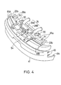
- Fig.4 is a perspective view of a nose unit.
- Fig.5 is a exploded perspective view of a nose unit.
- Fig.6 is a schematic perspective view of a unit base of a nose unit.
- Fig.7 is a schematic perspective view of a modified unit base of a nose unit.
- Fig.8 is a sectional view illustration a mounting at the last step.
- Figs.9-11 show the second embodiment, in which
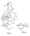
- Fig.9 is a detailed view around a bracket;
- Fig.10 is a sectional view taken on a line A-A of Fig.9;
- Fig.1 is a perspective view of a front part of a vehicle body.
- Figs.12-14 show a third embodiment, in which
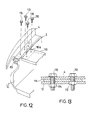
- Fig.12 is a detailed view around a bracket;
- Fig.13 is a sectional view on line C-C of Fig.16;
- Fig.14 is a perspective view of a front body of a vehicle body.
- Figs.15-21 show a forth embodiment of the present invention, in which
- Fig.15 is a diagram illustrating a relationship between a unit base and a jig for mounting a unit base;
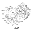
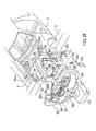
- Fig.16 is a exploded perspective view of a nose unit;
- Fig.17 is a descriptive diagram of a mounting for a nose unit to a front part of a vehicle body;
- Fig.18 is a diagram illustrating a front part of a vehicle body after a nose unit is mounted;
- Figs.19-21 are sectional views taken on lines X-X, Y-Y, Z-Z of Fig.17 respectively.
- Fig.22 is a descriptive diagram for a conventional art.
- The preferred embodiment will be described below with reference to the accompanying drawings.
- In Fig.1 illustrating a front part of a vehicle, reference numeral 1 designates a vehicle having a
nose unit 3 which is mounted on the front part of avehicle body 2.Front fenders 4 are provided on both sides of thebody 2, and abonnet 5 is provided on the front top of thevehicle body 2. - In the
vehicle body 2, as shown in detail in Fig. 2,front sideframes 13 are connected to the vehicle body underwheel aprons 12 forming right and left side walls of anengine room 11 and awheel apron reinforcement 14 are connected to the vehicle body above the wheel aprons 12 so that both top and bottom closed sectional constructions extending longitudinally of the vehicle body are formed. - A
bracket 15 projecting to the inner side of the vehicle body is provided around eachwheel apron reinforcement 14. Eachbracket 15, as shown in Fig. 3, comprises abase part 15a fitted to theadjacent wheel reinforcement 14 and amounting portion 15b extending inboard from thebase part 15a. Afitting portion 22b of a shroud upper 22 ofnose unit 3 is mounted to themounting portion 15b. Twonuts 16 are welded on the underside of the mountingpart 15b.Other brackets 17 are provided on the front top ends of thefront sideframes 13. - Mounting
flange portions wheel apron 12.Nuts 18 for fixing ashroud panel 21 bybolts 20 are welded on the undersurface of theflange portions nut 37 for fixing theshroud panel 21 and ajunction panel 31 by abolt 34 are welded on the undersurface of eachflange portion 12c. - Also,
front end panels 19 are provided on the front end portion of the wheel aprons 12. - The
nose unit 3 is constructed as illustrated in detail in Figs.4 and 5. The unit base of thenose unit 3 is connected to the shroud upper 22 extending in the widthwise direction of the vehicle body on the upper end portions of theshroud panels 21 as shown in Fig.6. This shroud upper 22 comprises avertical wall part 22A extending vertically and anupper wall part 22B extending rearwardly from the upper end of thevertical wall part 22A. A pair ofvertical members 23 are hanging down from a center part in the widthwise direction of theupper wall part 22B. - A
cross member 26 of a closed sectional construction, which is formed by contacting anupper member 26A with alower member 26B, is provided on the both lower ends of thevertical members 23. Anopening 21 a for later describedlump units shroud panel 21, however, the opening can be acutaway part 21 b instead of an opening as shown in Fig.7. - On the
cross member 26, supportingbrackets 27 for supporting acondenser 24A and aradiator 24B both of which are weight members are provided on the rear side, and supportingbrackets 28 for supporting anintercooler 51 are provided on the front side. Thecondenser 24A and theradiator 24B are connected integrally by a member (not shown in the drawings) the lower end portions thereof being supported by supportingbrackets 27 through rubber mount members, and the upper end portions thereof being fixed to fittingholes 21 a of anupper wall part 22B of the shroud upper 22 by tighteningbolts 33 throughbrackets 30. In Figs .6 and 7,reference numeral 29 designates a pulling hook fixed to the underside of thejunction panel 31. - A rear end portion of each
junction panel 31 of square cylindrical configuration is mounted to theshroud panel 21. As shown in Fig. 8, a rearend flange portion 31 a of thejunction panel 31 is positioned to the rear side of theshroud panel 21. Thejunction panel 31 and a front sideframe are clamped coaxially by the front sideframe 13 (anut 36 welded on the rear surface of the bracket 17) and a wheel apron 12 (nuts 37 welded or the rear surface of a theflange portion 12c) through ajunction plate 32 of flat plate configuration. -
Bolts 43 provided on abumper reinforcement 42 where abumper 41 is mounted to are fixed to a frontend flange portion 31 b of eachjunction panel 31. - The both ends of the
bumper 41 are also fixed to a mountingportion 4a of eachfront fender 4 of thevehicle body 2 bybolts 45 provided on thebumper 41 and bolts (not shown in the drawings) passing through afitting hole 41 a of thebumper 41. - Both ends 22b of the
upper wall parts 22B of the shroud upper 22 are overlapped onbrackets 15 and are clamped tobrackets 15 by bolts (only twobolts 36 of one mountingportion 22b are shown in Fig.5). - An upper part of
intercooler 51 is clamped to thevertical wall part 22A of the shroud upper 22 bybolts 53 throughbrackets 52. - A
radiator grille 54 is positioned at the front center part of the vehicle, both right and left mountingportions 54a thereof being fitted into fitting holes of thevertical wall parts 22A of the shroud upper 22. Acenter mounting portion 54b is fitted into a fitting hole of avertical member 56 of bonnet lock means 55. -
Reference numerals portions 61 a on the upper end of each unit are clamped to thevertical wall part 22A of the shroud upper 22 bybolts 62, and mountingportions 61 b on the lower end of each unit are clamped to theshroud panel 21 by bolts 63 (onlybolts lamp unit 61 A are illustrated in the drawing). -
Reference numerals 64, 65 are harness for connecting the electric system and are clamped to thesupport member 26 by fasteningbolts 67 into a mountingportion 66 and fitted into a fitting hole of theupper wall part 22B of the shroud upper 22 through mountingportions 68 respectively.Reference numerals 71 designate shock absorber members for the shock at opening/closing thebonnet 5 and connected to anupper wall part 22B of the shroud upper 22. - Since the mounting
portions 15b(mounting portions for the shroud upper) of thebrackets 15 for thewheel reinforcement 14 are projecting to the inner side of the vehicle body with respect to the fixing portion for thefront fenders 4 when thenose unit 3 is inserted to thevehicle body 2 from the front, thenose unit 3 won't interfere with thefront fenders 4 of thevehicle body 2 and it is positioned by overlapping a fixingportion 22b on both ends of the shroud upper 22 of thenose unit 3 with the mountingportions 15b ofbrackets 15 of thewheel reinforcements 14. - When the
bolts 46 are tightened into thenuts 16 of the mountingportions 15b ofbrackets 15 from the top, the nose unit 3 (a shroud upper 22) is fixed to thevehicle body 2. - In the above embodiment, each
bracket 15 is separate from itsadjacent wheel reinforcement 14, however, it can be integrally formed with thewheel reinforcement 14 or with awheel apron 12. - In the above embodiment,
bracket 15 is fixed to thewheel apron reinforcement 14, however, as shown in Figs.9-11, abracket 81 having a hollow could be used which is fixed on the engine room side of thewheel apron 12 and on further inner and lower than a mountingportion 4b of thevehicle body 2 of thefront fender 4 so that a fixingportion 82a of a shroud upper 82 is clamped to anupper surface 81 a of thebracket 81 bybolts 85. Thebracket 81 comprises aflange portion 81 b on its periphery, the flange portion may be fixed to the frontend flange portion 12d and aninner surface 12e of thewheel apron 12 by being welded or may be connected to awheel apron reinforcement 83.Reference numeral 84 designates a cross member for connecting right and left front side frames 3. - As shown in Figs. 12, 13 and 14, when a fixing
portion 110a for a shroud upper 110 is disposed to a mounting portion for thevehicle body 2 of thefront fender 4 on the inner side, abracket 111 for supporting the shroud upper 110 can be not fixed to both thevehicle body 2 and the shroud upper 110. - In other words, before the
nose unit 3 is mounted to thevehicle body 2, a first fixing portion is constructed by clamping abracket 111 to thefront fender 4, which is done by fastening abolt 113 wherein a base part of thebracket 111 is overlapped on the under side of thefront fender 4. Then thefront fender 4, where the base part of thebracket 111 is fixed to, and abracket 111 are overlapped on the top of thewheel apron 12 so that a second fixing portion is formed by clamping them by abolt 115 and anut 114. Through this, thebracket 111 is fixed to the wheel apron 12 (the vehicle body 2) together when thefront fender 4 is fixed to thewheel apron 12. - Under this condition, the
nose unit 3 is inserted and determines the position of it and a fixingportion 22b for the shroud upper 22 is clamped to thebracket 111 by abolt 116. When thefront fender 4 is replaced, it can be removed by untighteningbolts - Furthermore, on the above embodiment, the support member for supporting the heavyweight member such as a radiator comprises one member extending in the widthwise direction of the vehicle body, however, it may comprise two
support members 128 being spaced with a fixed distance in the widthwise direction. - As shown in Figs.15 and 16, the components are fitted to a
nose unit 121 wherein anose base 121 is put on ajig 122 for mounting the nose unit. - The
jig 122 for mounting the nose unit comprises abase part 122a extending in the widthwise direction of the vehicle body,vertical arm parts base part 122a, andarm parts arm parts base part 122a, three engagingpins arm parts pins cylinders pins - A
unit base 123 comprises right and leftshroud panels 125, a shroud upper 126 extending in the widthwise direction of the vehicle body and fixed to the upper end of theshroud panels 125, acenter steer 127 hanging down from the mid-position of the shroud upper 126 in the widthwise direction of the vehicle body, and first andsecond support members 128 each fixed to the lower end portion of eachshroud panel 125. - In detail, the shroud upper 126 comprises a
vertical wall part 126A extending vertically, anupper wall part 126B extending rearwardly from the upper end of thevertical wall part 126A, and arear wall part 126C extending downwardly from the rear end of theupper wall part 126B (Fig.21). The center steer 127 extending in the vertical direction of the vehicle body is hanging down from the midposition of thevertical wall part 126A in the widthwise direction of the vehicle body. - Each
support member 128 comprises anupper wall part 128a for supporting a lower part of aradiator 129 which is a heavyweight member, avertical wall part 128b extending downwardly from the front end of theupper wall part 128a and contacts theshroud side panel 125, and asupport part 128c for supporting acooler condenser 130 which is a heavyweight member and projects to the front from the lower end of thevertical wall part 128b. - On both ends of the shroud upper 126 (the
vertical wall part 126B) of theunit base 123, on the lower end of thecenter steer 127, and on the front part of thesupport members 128, an engaging part comprisingfitting holes pins nose unit 121 is determined by the relationship between the engagingpins fitting holes - A lower end portion of a
radiator 129 and thecooler condensor 130 is supported byupper wall parts 128a of the support members 128 (fitting holes 128e) andsupport parts 128c (fitting holes) through rubber mounts 131 A, 131B. The upper end portion of theradiator 129 and thecooler condenser 130 are clamped to theupper wall part 126B (fitting holes) of the shroud upper 126 reinforced by a radiator reinforcement 133 (refer to Fig. 23) and avertical wall part 126A bybolts brackets reference numeral 157 designates a nut for screwed on thebolt 134A which is already welded on the underside of anupper wall part 126B of the shroud upper 126 through theradiator reinforcement 133. - Mounting
portions 125a are formed around the lower end portion of theshroud panel 125 so that twoinner bolts 137A out of four-in-a-set bolts disposed on thebumper reinforcement 136, which abumper face 135 is mounted to, are fixed to the mountingportions 125a as a temporarily mounting for forming a unit by using anut 142. The other outer twobolts 137B are fixed to afront flange part 139a of a frame outer 139A of afront frame 139 throughside part 138a of across member 138 when mounting anose unit 121 to a front part of a vehicle so that thebumper reinforcement 136 is connected to thevehicle body 2 directly (Fig.20). - Both ends of the
upper wall part 126B of the shroud upper 126 are clamped to ashroud bracket 141 bybolts 140. As shown in Fig.18, a base part of thisshroud bracket 141 is clamped between thewheel apron reinforcement 14 and thefront fender 4 by abolt 143 and anut 144. - Accordingly, the
support member 128 is mounted by thecross member 138 wherein thenose unit 121 is installed in the front part of thevehicle body 2 and fixed to a front wall part and an upper wall part of anupper member 138A of thecross member 138 bybolts nuts upper wall part 128a and afront wall part 128b of the support member 128 (Fig.21). -
Reference numeral 151 designates a cooler receiver, the side part thereof is clamped to thecenter steer 127 bybolts 153 throughbracket 152. A joint metal fitting 155 of ahorse member 154 from acooler receiver 151 is connected to a joint metal fitting of ahorse member 155A of thecooler condenser 130. -
Reference numeral 161 designates bonnet lock means clamped to avertical wall part 126A of the shroud upper 126 bybolts 162 through thecenter steer 127. -
Reference numeral 163 designates a power steering pipe clamped to acenter steer 127 and one of theshroud panels 125 through a mounting implement 164 andbolts 165.Reference numerals 166 designate horn members fixed to thecenter steer 127 by abolt 167. - Right and left
lamp units 172 comprising aradiator grille 171, ahead lamp 172A, and afront combination lamp 172B, those positioned front center part of the vehicle, are mounted to the nose unit and the vehicle body after thenose unit 121 is mounted to the vehicle body as shown in Fig.18, this step differs from the first embodiment. In detail, theradiator grille 171 comprises engagingparts side engaging parts vertical wall part 126A (a fitting hole) of the shroud upper 126 and acenter engaging part 171 b connected detacheably to avertical wall part 126A (a fitting hole) of the shroud upper 126 through bonnet lock means 161. In thelamp unit 172, mountingportions head lamp 172A side are clamped to a side end portion of theshroud panel 125 and unupper wall part 126B (a fitting hole) of the shroud upper 126 bybolts portion 172c on thefront combination lamp 172B side is fitted into an engagingportion 184 of the wheel apron. - According to the above structure, the components are mounted to the unit base wherein the
unit base 123 is supported by thejig 122 for mounting the nose unit and also positioned the relationship between the engagingpins 124A-124E and thefitting holes - After fitting components to the nose unit, as shown in Fig.17, the
nose unit 121 is put on atruck 173 with thejig 122 and mounted to the front part of thevehicle body 2 moving on an assembling line S (a main line). At this moment in this embodiment, in order to lessen the deformation of the vehicle body 2 (so to speak a front opening), although engaging projectingparts 174a of adeformation preventing tool 174 for preventing the deformation is detacheably engaged withengaging portions 2A of both right and left sides of thevehicle body 2, engagingportions 2A and thedeformation preventing tool 174 can be excluded since thecross member 138 has an effect for preventing a deformation of the front part of a vehicle. - Thus, the
center steer 127 and thesupport member 128 are clamped to thecross member 138 by tightening thebolt 147 into anut 146 throughfastener bolt 148 and anut 145. Also, thebumper reinforcement 136 is clamped to aside part 138a of thecross member 138 by screwing anut 149 on abolt 137B by afastener 177. - Moreover, the shroud upper 126 is clamped to the
shroud bracket 141 by screwingnuts 150 onbolts 140 by a fastener 178. - The
radiator grille 171 and thelamp unit 172 are installed after thus thenose unit 121 is mounted to the front part of thevehicle body 2.
Claims (6)
characterized in that
Applications Claiming Priority (2)
| Application Number | Priority Date | Filing Date | Title |
|---|---|---|---|
| JP33314089 | 1989-12-21 | ||
| JP333140/89 | 1989-12-21 |
Publications (3)
| Publication Number | Publication Date |
|---|---|
| EP0437780A1 EP0437780A1 (en) | 1991-07-24 |
| EP0437780B1 true EP0437780B1 (en) | 1995-10-11 |
| EP0437780B2 EP0437780B2 (en) | 1998-08-19 |
Family
ID=18262741
Family Applications (1)
| Application Number | Title | Priority Date | Filing Date |
|---|---|---|---|
| EP19900124792 Expired - Lifetime EP0437780B2 (en) | 1989-12-21 | 1990-12-19 | Front body structure of a vehicle |
Country Status (2)
| Country | Link |
|---|---|
| EP (1) | EP0437780B2 (en) |
| DE (1) | DE69022967T3 (en) |
Families Citing this family (14)
| Publication number | Priority date | Publication date | Assignee | Title |
|---|---|---|---|---|
| FR2713579B1 (en) * | 1993-12-15 | 1996-03-01 | Ecia Equip Composants Ind Auto | Support frame for a motor vehicle facade. |
| IT1273160B (en) * | 1994-04-27 | 1997-07-07 | Fiat Auto Spa | MOTOR VEHICLE STRUCTURE AND ASSEMBLY PROCEDURE OF A MOTOR VEHICLE WITH SUCH A STRUCTURE |
| DE19647928A1 (en) * | 1996-11-20 | 1998-05-28 | Opel Adam Ag | Front bodywork for a motor vehicle |
| EP1440871A3 (en) * | 1998-07-15 | 2006-06-28 | Magna International Inc. | Motor vehicle end module assembly |
| US6282769B1 (en) | 1998-07-15 | 2001-09-04 | Cosma International Inc. | Motor vehicle end module assembly |
| FR2783797B1 (en) * | 1998-09-30 | 2000-12-29 | Ecia Equip Composants Ind Auto | MOTOR VEHICLE, FRONT BLOCK FOR THIS VEHICLE AND METHOD OF MOUNTING THE VEHICLE |
| DE19912181B4 (en) * | 1999-03-18 | 2008-03-06 | Volkswagen Ag | Method for the tolerance-accurate assembly of components of a motor vehicle front-end vehicle and arrangement for carrying out the method |
| IT1308049B1 (en) * | 1999-05-25 | 2001-11-29 | Magneti Marelli Climat Srl | PRE-ASSEMBLED FRONT MODULE FOR VEHICLES |
| JP3755354B2 (en) * | 1999-10-29 | 2006-03-15 | 日産自動車株式会社 | Front fender front end structure of the vehicle |
| DE10058115B4 (en) * | 2000-11-22 | 2016-02-04 | Volkswagen Ag | Subframe module |
| DE60110526T2 (en) * | 2000-11-28 | 2005-11-17 | Daihatsu Motor Co., Ltd., Ikeda | Vehicle body front structure for automobiles |
| DE10207025A1 (en) | 2002-02-20 | 2003-08-28 | Behr Gmbh & Co | Mounting for vehicle radiator comprises clip at top and pivot at bottom |
| DE10260530B4 (en) * | 2002-12-21 | 2015-09-03 | Volkswagen Ag | Method for producing a one-piece reinforcing sheet |
| JP2006103643A (en) * | 2004-10-08 | 2006-04-20 | Calsonic Kansei Corp | Radiator core support structure |
Family Cites Families (4)
| Publication number | Priority date | Publication date | Assignee | Title |
|---|---|---|---|---|
| US2715448A (en) * | 1952-01-03 | 1955-08-16 | Chrysler Corp | Front sheet metal construction for automotive vehicles |
| NL270623A (en) * | 1960-11-08 | |||
| JPS58152673A (en) * | 1982-03-08 | 1983-09-10 | Mazda Motor Corp | Front vehicle body construction of automobile |
| JPS6364883A (en) * | 1986-09-04 | 1988-03-23 | Mazda Motor Corp | Structure for front frame of automobile |
-
1990
- 1990-12-19 DE DE1990622967 patent/DE69022967T3/en not_active Expired - Lifetime
- 1990-12-19 EP EP19900124792 patent/EP0437780B2/en not_active Expired - Lifetime
Also Published As
| Publication number | Publication date |
|---|---|
| DE69022967D1 (en) | 1995-11-16 |
| DE69022967T2 (en) | 1996-05-30 |
| EP0437780A1 (en) | 1991-07-24 |
| DE69022967T3 (en) | 1999-04-15 |
| EP0437780B2 (en) | 1998-08-19 |
Similar Documents
| Publication | Publication Date | Title |
|---|---|---|
| EP0437781B1 (en) | Front body structure of vehicle | |
| US5358304A (en) | Front body structure of a vehicle and assembling method | |
| EP0437780B1 (en) | Front body structure of a vehicle | |
| US7390047B2 (en) | Front part structure of vehicle body | |
| US20030089540A1 (en) | Structure for mounting box for containing high-voltage electrical equipment on vehicle | |
| EP0919452B1 (en) | Bumper-mounting structure for frame-mounted-body vehicle | |
| JP2907502B2 (en) | How to assemble the front body of the vehicle | |
| JP2898339B2 (en) | Vehicle front body structure and vehicle body assembly method | |
| US20240239147A1 (en) | Motor Vehicle Having a Suspension Strut | |
| KR940006236B1 (en) | Structure for front body of automobile and its assembly | |
| JP2001012308A (en) | Fuel cylinder mounting structure for automobile with fuel cylinder | |
| JP2565503Y2 (en) | Mounting structure of high mount stop lamp | |
| JP2837721B2 (en) | Vehicle front body structure and method of assembling the same | |
| JPH0330224Y2 (en) | ||
| JPH04169326A (en) | Agricultural working car | |
| JP2571893Y2 (en) | Car body structure | |
| JPH0769260A (en) | Rear fender installing structure for motorcycle | |
| JP2535365Y2 (en) | Frame fastening structure | |
| JP2851341B2 (en) | Vehicle front body structure and method of assembling the same | |
| JP2933659B2 (en) | How to assemble the front body of a car | |
| JPH07112778B2 (en) | Car door structure | |
| KR100345834B1 (en) | Structure for assembling fuel tank in vehicle | |
| JPH085408B2 (en) | Body front structure | |
| JPH0433153Y2 (en) | ||
| JP3018863B2 (en) | Car front body structure |
Legal Events
| Date | Code | Title | Description |
|---|---|---|---|
| PUAI | Public reference made under article 153(3) epc to a published international application that has entered the european phase |
Free format text: ORIGINAL CODE: 0009012 |
|
| AK | Designated contracting states |
Kind code of ref document: A1 Designated state(s): DE FR GB |
|
| 17P | Request for examination filed |
Effective date: 19911031 |
|
| 17Q | First examination report despatched |
Effective date: 19930602 |
|
| GRAA | (expected) grant |
Free format text: ORIGINAL CODE: 0009210 |
|
| AK | Designated contracting states |
Kind code of ref document: B1 Designated state(s): DE FR GB |
|
| REF | Corresponds to: |
Ref document number: 69022967 Country of ref document: DE Date of ref document: 19951116 |
|
| ET | Fr: translation filed | ||
| PLBI | Opposition filed |
Free format text: ORIGINAL CODE: 0009260 |
|
| PLBF | Reply of patent proprietor to notice(s) of opposition |
Free format text: ORIGINAL CODE: EPIDOS OBSO |
|
| 26 | Opposition filed |
Opponent name: MERCEDES-BENZ AG Effective date: 19960711 |
|
| PLBF | Reply of patent proprietor to notice(s) of opposition |
Free format text: ORIGINAL CODE: EPIDOS OBSO |
|
| PLBF | Reply of patent proprietor to notice(s) of opposition |
Free format text: ORIGINAL CODE: EPIDOS OBSO |
|
| PLAW | Interlocutory decision in opposition |
Free format text: ORIGINAL CODE: EPIDOS IDOP |
|
| PLAW | Interlocutory decision in opposition |
Free format text: ORIGINAL CODE: EPIDOS IDOP |
|
| PUAH | Patent maintained in amended form |
Free format text: ORIGINAL CODE: 0009272 |
|
| STAA | Information on the status of an ep patent application or granted ep patent |
Free format text: STATUS: PATENT MAINTAINED AS AMENDED |
|
| 27A | Patent maintained in amended form |
Effective date: 19980819 |
|
| AK | Designated contracting states |
Kind code of ref document: B2 Designated state(s): DE FR GB |
|
| ET3 | Fr: translation filed ** decision concerning opposition | ||
| PGFP | Annual fee paid to national office [announced via postgrant information from national office to epo] |
Ref country code: FR Payment date: 20001212 Year of fee payment: 11 |
|
| PGFP | Annual fee paid to national office [announced via postgrant information from national office to epo] |
Ref country code: GB Payment date: 20001213 Year of fee payment: 11 |
|
| PG25 | Lapsed in a contracting state [announced via postgrant information from national office to epo] |
Ref country code: GB Free format text: LAPSE BECAUSE OF NON-PAYMENT OF DUE FEES Effective date: 20011219 |
|
| REG | Reference to a national code |
Ref country code: GB Ref legal event code: IF02 |
|
| GBPC | Gb: european patent ceased through non-payment of renewal fee |
Effective date: 20011219 |
|
| PG25 | Lapsed in a contracting state [announced via postgrant information from national office to epo] |
Ref country code: FR Free format text: LAPSE BECAUSE OF NON-PAYMENT OF DUE FEES Effective date: 20020830 |
|
| REG | Reference to a national code |
Ref country code: FR Ref legal event code: ST |
|
| PGFP | Annual fee paid to national office [announced via postgrant information from national office to epo] |
Ref country code: DE Payment date: 20091217 Year of fee payment: 20 |
|
| PG25 | Lapsed in a contracting state [announced via postgrant information from national office to epo] |
Ref country code: DE Free format text: LAPSE BECAUSE OF EXPIRATION OF PROTECTION Effective date: 20101219 |