EP0437584B1 - Flüssigkeitslose befestigung mit bewegungsdämpfung in mehreren richtungen - Google Patents
Flüssigkeitslose befestigung mit bewegungsdämpfung in mehreren richtungen Download PDFInfo
- Publication number
- EP0437584B1 EP0437584B1 EP90912321A EP90912321A EP0437584B1 EP 0437584 B1 EP0437584 B1 EP 0437584B1 EP 90912321 A EP90912321 A EP 90912321A EP 90912321 A EP90912321 A EP 90912321A EP 0437584 B1 EP0437584 B1 EP 0437584B1
- Authority
- EP
- European Patent Office
- Prior art keywords
- resiliently deformable
- rib means
- ring
- flanges
- further characterized
- Prior art date
- Legal status (The legal status is an assumption and is not a legal conclusion. Google has not performed a legal analysis and makes no representation as to the accuracy of the status listed.)
- Expired - Lifetime
Links
- 238000013016 damping Methods 0.000 title claims abstract description 40
- 230000033001 locomotion Effects 0.000 claims abstract description 46
- 239000013536 elastomeric material Substances 0.000 claims abstract description 8
- 230000002093 peripheral effect Effects 0.000 claims description 17
- 239000012530 fluid Substances 0.000 claims description 12
- 238000010276 construction Methods 0.000 description 9
- 238000004519 manufacturing process Methods 0.000 description 7
- 229920001971 elastomer Polymers 0.000 description 5
- 239000000463 material Substances 0.000 description 3
- 239000000203 mixture Substances 0.000 description 3
- 239000005060 rubber Substances 0.000 description 3
- 239000000806 elastomer Substances 0.000 description 2
- 229910052751 metal Inorganic materials 0.000 description 2
- 239000002184 metal Substances 0.000 description 2
- 238000000034 method Methods 0.000 description 2
- 229920003048 styrene butadiene rubber Polymers 0.000 description 2
- BFKJFAAPBSQJPD-UHFFFAOYSA-N tetrafluoroethene Chemical group FC(F)=C(F)F BFKJFAAPBSQJPD-UHFFFAOYSA-N 0.000 description 2
- 239000004677 Nylon Substances 0.000 description 1
- 229910000831 Steel Inorganic materials 0.000 description 1
- 239000002174 Styrene-butadiene Substances 0.000 description 1
- 238000005299 abrasion Methods 0.000 description 1
- 239000000654 additive Substances 0.000 description 1
- 230000000996 additive effect Effects 0.000 description 1
- 239000000853 adhesive Substances 0.000 description 1
- 230000001070 adhesive effect Effects 0.000 description 1
- 230000004075 alteration Effects 0.000 description 1
- 229910052782 aluminium Inorganic materials 0.000 description 1
- XAGFODPZIPBFFR-UHFFFAOYSA-N aluminium Chemical compound [Al] XAGFODPZIPBFFR-UHFFFAOYSA-N 0.000 description 1
- 239000011248 coating agent Substances 0.000 description 1
- 238000000576 coating method Methods 0.000 description 1
- 230000006835 compression Effects 0.000 description 1
- 238000007906 compression Methods 0.000 description 1
- 238000006073 displacement reaction Methods 0.000 description 1
- 230000000694 effects Effects 0.000 description 1
- 239000000945 filler Substances 0.000 description 1
- 239000011521 glass Substances 0.000 description 1
- 239000004519 grease Substances 0.000 description 1
- 238000002955 isolation Methods 0.000 description 1
- 238000012986 modification Methods 0.000 description 1
- 230000004048 modification Effects 0.000 description 1
- 230000007935 neutral effect Effects 0.000 description 1
- 229920001778 nylon Polymers 0.000 description 1
- 230000010355 oscillation Effects 0.000 description 1
- 229920001296 polysiloxane Polymers 0.000 description 1
- 229920002545 silicone oil Polymers 0.000 description 1
- 239000010959 steel Substances 0.000 description 1
- 238000003466 welding Methods 0.000 description 1
Images


Classifications
-
- F—MECHANICAL ENGINEERING; LIGHTING; HEATING; WEAPONS; BLASTING
- F16—ENGINEERING ELEMENTS AND UNITS; GENERAL MEASURES FOR PRODUCING AND MAINTAINING EFFECTIVE FUNCTIONING OF MACHINES OR INSTALLATIONS; THERMAL INSULATION IN GENERAL
- F16F—SPRINGS; SHOCK-ABSORBERS; MEANS FOR DAMPING VIBRATION
- F16F7/00—Vibration-dampers; Shock-absorbers
- F16F7/08—Vibration-dampers; Shock-absorbers with friction surfaces rectilinearly movable along each other
- F16F7/087—Elastomeric surface effect dampers
-
- F—MECHANICAL ENGINEERING; LIGHTING; HEATING; WEAPONS; BLASTING
- F16—ENGINEERING ELEMENTS AND UNITS; GENERAL MEASURES FOR PRODUCING AND MAINTAINING EFFECTIVE FUNCTIONING OF MACHINES OR INSTALLATIONS; THERMAL INSULATION IN GENERAL
- F16F—SPRINGS; SHOCK-ABSORBERS; MEANS FOR DAMPING VIBRATION
- F16F13/00—Units comprising springs of the non-fluid type as well as vibration-dampers, shock-absorbers, or fluid springs
- F16F13/04—Units comprising springs of the non-fluid type as well as vibration-dampers, shock-absorbers, or fluid springs comprising both a plastics spring and a damper, e.g. a friction damper
Definitions
- the present invention relates to non-fluid mounts capable of damping motion in at least two directions.
- fluid mounts have found application in a variety of uses where motion damping is required.
- engines are mounted to frames utilizing fluid mounts which can be designed to provide desired amplitude and/or frequency responsive vibration isolation.
- An example of such a mount is disclosed in U.S. Patent No. 4,709,907 owned by the assignee of the present invention.
- fluid mounts may function satisfactorily for their intended purposes
- fluid mounts in general, have certain drawbacks. For instance, they are somewhat difficult to manufacture on a mass-production basis because of the need both to fill the mount and to insure against leakage in use.
- fluid mounts are not as inexpensive as desired for applications in which cost and reliability are important considerations.
- the Gaydecki isolator includes a first member adapted to be connected to a first object, a second member adapted to be connected to a second object, a first resiliently deformable block mounted on the second member defining a first resiliently deformable layer extending in a first direction and a second resiliently deformable layer mounted on the first member, and rigid rib means engaging one of said resiliently deformable layers and slidably deforming said layer to damp relative motion between said first and second members.
- Gaydecki isolator may function satisfactorily to damp motion along a single axis
- applications such as the aforedescribed automotive engine to frame mounting application, which require damping along a plurality of axes, such as the X, Y and Z axes.
- a fluidless mount which can be manufactured readily utilizing conventional mass-production manufacturing techniques and equipment.
- mount of this type which can provide amplitude-sensitive damping.
- a primary object of the present invention is to provide a novel fluidless mount which can damp vibrations in more than one direction.
- Another object of the present invention is to provide an improved non-fluid mount which can damp vibrations imparted either independently or simultaneously along the X, Y and Z axes.
- a further object of the present invention is to provide a unique fluidless mount which can provide different levels of damping in different directions in response to different amplitudes of input motion.
- Yet another object of the present invention is to provide a rugged, reliable, readily manufacturable fluidless mount which can damp vibrations imparted on one or more of three orthogonal intersecting axes.
- the present invention provides a mount including the features of claim 1 for damping motion in at least two directions.
- the first member may be a tube, and the second may be a shell, surrounding the first member.
- the resilient block preferably has an interior surface forming a cavity therein.
- the second resiliently deformable layer is preferably provided on a flange mounted on the first member for movement therewith in the second direction in the cavity.
- a lost motion connection is provided between the rigid rib means and either or both of the members to accommodate small amplitude displacements with little or no damping. Another embodiment provides certain additional advantages including accommodating greater cocking motions.
- FIG. 1 illustrates one preferred embodiment of a mount 10 which embodies the present invention.
- the mount 10 is of the so-called tube form variety which comprises a first member, such as a bushing 11 which is adapted to be connected to a first object, such as the spaced parallel mounting plates 12 and 13, by means of a bolt 14, shown in phantom.
- a second member, such as a cylindrical tube, or shell, 15 surrounds the first member 11 and is coaxial therewith about a central longitudinal axis Z.
- the second member 15 is adapted to be connected to a second object, as by being inserted in a bore of a base, or connecting rod (not shown).
- the first and second members 11 and 15 are mounted for movement relative to one another on the Z axis, and laterally, or transversely of the Z axis on the X and Y axes by means of a resilient block 16 interposed between the first and second members 11 and 15.
- the resilient block 16 is of an elastomeric material, such as rubber and is bonded to the members 11 and 15.
- the elastomeric block 16 permits the inner, or first member 11 to move vertically on the Z axis, horizontally on the X axis, and horizontally on the Y axis (perpendicular to the plane of the drawing).
- the elastomeric block 16 has an internal annular cavity, or chamber 17 which contains a damping assembly indicated generally at 18.
- the damping assembly 18 includes a first resiliently deformable layer 19 which extends along the inner periphery of the shell 15 along the Z axis.
- the first layer 19 has a constant relatively uniform thickness in the direction of the Z axis and has a predetermined axial extent in that direction.
- the first layer 19 has a certain minimum thickness in the radial direction, i.e. transverse, or lateral to the path of movement of the bushing 11 on its longitudinal, or Z axis.
- the first resiliently deformable layer 19 is molded integral with the resilient block 16, and the cylindrical inner peripheral surface 19′ of the first deformable layer 19 is smooth.
- the damping assembly 18 also includes at least one, and preferably a pair, of second resiliently deformable layers 20 and 21 contained in the cavity 17.
- the layers 20 and 21 are bonded to circular washer-like flanges 22 and 23, respectively.
- the washer-like flanges are mounted in the cavity 17 with their deformable surfaces 20 and 21 in axially spaced confronting relation with a gap G disposed therebetween.
- the flanges 22 and 23 are located on the bushing 11 between shoulders 11 a and 11 b provided at axially spaced locations and move in unison with the bushing 11.
- the layers 20 and 21 extend continuously about the bushing 11, and are of a substantially constant and uniform thickness for a predetermined extent in the Z direction.
- a ring-like,or annular, slide element 25 is mounted in the gap G.
- the ring-like slide element 25 surrounds the bushing 11 and has an inner circumferential portion 25 a engaged between the opposed resilient layers 20 and 21 and has an outer peripheral portion 25 b which engages the peripheral resilient layer 19.
- the circumferential portion 25 a has opposite sides, each of which, such as the upper side, has a pair of parallel continuous ridges 27 a and 28 a separated by a groove 29 a .
- ridges and grooves 27 b , 28 b and 29 b are provided on the opposite, or lower side of the slide ring 25.
- a similar pair of ridges 30 and 31 are provided on the outer peripheral portion 25 b of the slide ring 25, and they are separated by a groove 32.
- the ridges and grooves on the slide ring element 25 are configured relative to the elastomeric layers 19, 20 and 21 to cause the elastomeric layers to deform adjacent their zones of engagement with the ridges.
- any movement of the slide ring element 25 under pressure relative to its engaged elastomeric layer causes the elastomeric layer in the zone adjacent the point of contact to move in a wave-like manner, either ahead of or behind the ridge.
- Such wave-like movement of the elastomeric layer develops hysteresis within the elastomeric layer, and such hysteresis acts in a well-known manner to absorb energy and thereby to damp relative movement.
- the mount 10 is fabricated in two identical sections 10 a and 10 b which are divided horizontally in the plane of the X and Y axes.
- the washer-like flanges 22 and 23 Prior to assembly of the sections 10 a and 10 b into the configuration illustrated in FIGS. 1 and 2, the washer-like flanges 22 and 23 are each first slid axially on their respective reduced-diameter portions of the bushing 11 into engagement with their respective shoulders 11 a and 11 b .
- the slide-ring 25 is placed in the gap G, and the sections 10 a and 10 b are forced axially toward one another into the assembled position illustrated in FIG. 2.
- adjacent surfaces may be provided with an appropriate adhesive to bond the elastomeric portions together along the horizontal line of juncture of the mount sections 10 a and 10 b .
- the connecting bolt 14 will provide clamping pressure in the Z axial direction; however, in applications where a connecting bolt 14 is not utilized, the sections 10 a and 10 b may be connected together as by spot welding at peripheral locations externally of the sleeve 15 and internally of the bushing 11, although this mode of providing clamping pressure may increase manufacturing costs somewhat.
- any movement of the bushing 11 relative to the sleeve 15 causes some relative movement to occur between the slide-ring 25 and either the elastomeric layer 19 or the elastomeric layers 20 and 21.
- virtually all relative motion is subject to damping.
- damping is undesirable, and it may be desired either to provide for a limited range of relative movement to occur before damping is induced or to provide different degrees of damping in different directions.
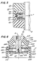
- FIG. 4 is provided.
- FIG. 4 is similar in most respects to the embodiment of FIGS. 1-3, except for a novel slide-ring assembly 125.
- the slide-ring 25 is of one-piece construction.
- the slide-ring assembly 125 is of multi-piece construction which provides a lost motion connection between the sleeve 111 and bushing 115 in at least one direction, and preferably in directions along all three orthogonal intersecting X, Y and Z axes.
- the slide-ring assembly 125 includes a rigid annular carrier ring element 126 which has an outer peripheral groove 126 a that slidably receives a radially-inwardly extending flange portion 140 a of a rib providing means 140.
- the rib providing means 140 has a profile which is like in configuration to the ridges and grooves provided in the embodiment of FIGS. 1-3 and cooperates in a similar fashion to deform the elastomeric layer 119 in response to relative movement between the bushing 111 and sleeve 115 along the Z axis.
- the peripheral groove 126 a is dimensioned larger relative to the width of the flange 140 a to provide a clearance in the Z direction.
- the magnitude of the clearance is preselected to enable the bushing 111, and hence the carrier ring 126, to move a predetermined limited amount before the slide-element 140 is engaged and displaced along the elastomeric layer 119.
- the slide-element 140 may be assembled on its carrier ring 126 either by being split, much like a piston ring, or by splitting the carrier ring 126 into upper and lower sections along a horizontal plane which intersects the peripheral groove 126 a .
- the carrier ring 126 is provided with a circumferential region 126 b of reduced thickness in the region of the gap G between the elastomeric layers 120 and 121.
- Slide-elements 141 and 142 of identical construction are mounted on opposite sides of the carrier ring 126 in the region of the reduced thickness portion 126 b .
- Upper and lower annular shoulders 126′ and 126 ⁇ are provided on the carrier ring 126 outwardly of the reduced thickness portion 126 b .
- the present invention also provides an embodiment which is particularly suited for use in mounting the engine of a vehicle to its frame in a manner providing multi-dimensional damping and accommodating cocking motions.
- the mount 210 of FIG. 6 is provided.
- the mount 210 includes a stem 211 extending vertically on the Z axis and adapted at its upper end to threadedly receive a mounting bolt (not shown).
- a drawn metal shell 215 surrounds the lower portion of the stem 211 and is relatively movably connected thereto by a resilient elastomeric block 219 having an upper frusto-conical portion 219 a extending between and bonded to a bulbous portion 211 a of the stem 211 and an outturned peripheral flange 215 a of the shell 215.
- the lower portion 215 b of the shell 215 is cylindrical and has an outturned mounting flange, and the inside of the lower portion 215 b of the shell 215 has a layer of elastomeric material 219 b bonded thereto.
- the layer 219 b has an inner peripheral surface 219′ which defines a cavity 217 that receives a damping assembly 218.
- the damping assembly 218 is similar in construction to the assembly 18 in the embodiment of FIGS. 1-3, but with certain differences. It should be understood, of course, that the damping assembly which incorporates lost motion connections, such as illustrated in the embodiment of FIG. 4, may also be utilized in the embodiment of FIG. 6 in those applications which warrant amplitude-sensitive damping.
- the damping assembly 218 includes a slide-ring 225, like in construction to the slide-ring 25 in FIG. 2, and upper and lower washer-like flange elements 222 and 223 to which are bonded resilient layers 220 and 221, respectively.
- the elastomeric layers 220 and 221 wrap around the outer peripheral edges of the flanges 222 and 223 to provide snubbing in the X and Y directions.
- the upper portion 219 a of the resilient bock 219 has a portion 219 c which overlies the outer peripheral portion of the upper flange 222 to provide snubbing in the Z direction.
- the upper washer-like flange 222 abutts against a shoulder 211 a on the stem 211, and the lower washer-like flange 223 is mounted to the stem 211 by means of a washer 245 and a threaded fastener 246 received axially in the bottom of the stem 211.
- the slide-ring 225 is clamped firmly between the washer-like flanges 222 and 223 by a form of clamping means which is structurally different from that utilized in the aforementioned embodiments but which is functionally similar.
- this embodiment has the advantage of being straightforward to assemble. It also permits a greater degree of cocking motion to be accommodated and damped because the bulk of the elastomeric block is disposed primarily to one side of the damping assembly 218, rather than being located on both sides as in the aforementioned embodiments.
- the present invention enables different levels of damping to be provided in different directions by a proper selection of the coefficients of friction between relatively slidable parts.
- the elastomeric layers 20 and 21 bonded to the washers 22 and 23 in the embodiment of FIG. 2 can be different in composition from the elastomeric material forming the wall 19.
- different pressures may be applied in the Z direction than in the X and Y directions, as by varying the axial spacing between the shoulders 11 a and 11 b , or the thickness of the layers 19, 20 and 21 relative to a slide-ring 25 of a particular dimensional configuration.
- the profile of the ridges and grooves in the circumferential portion of the slide-ring 25 may be different from the profile of the ridges and grooves on the peripheral portion.
- the elastomeric material utilized to provide all the layers is preferably of a composition which is abrasion resistant, highly damped and resistant to crack propagation.
- Such an elastomeric material may be a blend of natural and synthethic rubber components, such as styrene butadiene rubber (or an SBR type material).
- the elastomeric layers are preferably precompressed to a predetermined extent, preferably in a range of about 5% to about 30% of their thickness in the direction of compression in order to provide acceptable damping and service life.
- the slide element 25 may be fabricated of a metal, such as steel, aluminum or the like, which is coated with a tetrafluoroethylene-filled silicone grease or other antifriction coating, or it may be molded of polymeric material which is internally lubricated and reinforced, such as glass reinforced nylon having up to about 5 to 30%, by weight, of tetrafluoroethylene filler and up to about 2%, by weight, of silicone oil additive.
- the surface finish is most important for improved life and should be in the 1 to 25 microinch range for best results.
- the coefficient of sliding friction between the carrier element 126 and the ribbed and grooved elements 140-142 carried thereon is important for the coefficient of sliding friction between the same elements and their engaged elastomeric layers in order to ensure that the elastomeric layers 120 and 121 are coupled with the slide elements 141 and 142 for causing them to slide relative to the carrier ring 126 before the limits of motion are reached in the X and Y directions, and to permit limited motion in the Z direction before the limits of motion are reached between the carrier ring 126 and the peripheral slide element 140.
- the coefficient of sliding friction between the elements 140-142 and their associated elastomeric layers and carrier ring 126 are preferably in a predetermined ratio with respect to one another.
- the coefficient of sliding friction between the carrier ring 126 and the slide elements 141 and 142 is lower than the coefficient of sliding friction between the elements 140 and 142 and their engaged elastomeric layers 120 and 121, respectively, by a ratio in a range of about 1:3 to about 1:15.
- the range of lost motion provided by the construction illustrated is typically in a range of about .127mm (0.005 inches) to about 1.52mm (0.060 inches).
- the present invention now provides an improved mounts which provide damping in a plurality of directions without requiring fluid as a working medium.
- Their design is such as to enable different levels of damping to be incorporated in different directions without major revisions in overall construction.
- the mounts of the present invention can, therefore, be designed in a straightforward manner and manufactured readily utilizing known manufacturing techniques.
- the mounts overcome many of the drawbacks of known fluid-filled vibrations isolators.
- the damping results primarily hysteresis in the elastomer.
- the hysteresis damping can be supplemented by significant amounts of either friction damping or viscous shear damping. The exact proportions depend upon the application and specific design geometries.
Landscapes
- Engineering & Computer Science (AREA)
- General Engineering & Computer Science (AREA)
- Mechanical Engineering (AREA)
- Vibration Prevention Devices (AREA)
- Combined Devices Of Dampers And Springs (AREA)
- Springs (AREA)
Claims (11)
- Flüssigkeitslose Befestigung (10) zum Dämpfen der Bewegung in wenigstens zwei Richtungen mit einem ersten Teil (11), das mit einem ersten Gegenstand (12, 13) verbindbar ist, einem zweiten Teil (15), das mit einem zweiten Gegenstand verbindbar ist, einem ersten elastisch verformbaren Block (16), der zwischen den Teilen (11, 15) angeordnet ist und das erste Teil (11) für eine Translation in einer ersten Richtung längs und relativ zum zweiten Teil (15) und für eine Bewegung in einer zweiten Richtung seitlich zur ersten Richtung haltert, wobei das zweite Teil (15) eine erste elastisch verformbare Lage (19) bestimmt, die sich in der ersten Richtung erstreckt, und eine zweite elastisch verformbare Lage (20, 21), die am ersten Teil befestigt ist, und einem starren Rippenmittel (25), das mit den beiden elastisch verformbaren Lagen (19, 20, 21) in Eingriff ist und die Lagen gleitend verformt, um die Relativbewegung zwischen dem ersten und zweiten Teil (11, 15) zu dämpfen,
dadurch gekennzeichnet,
daß sich die zweite elastisch verformbare Lage (20, 21) längs der zweiten Seitenrichtung erstreckt und daß das starre Rippenmittel (25) von einem der ersten und zweiten Teile (11, 15) mittels seiner entsprechenden elastisch verformbaren Lage (19, 20, 21) gehaltert ist, wobei eine Bewegung des einen Teils die gleitend verformende Bewegung des starren Rippenmittels längs und relativ zur Lage verursacht, die zum anderen der zwei Teile gehört. - Befestigung nach Anspruch 1, dadurch gekennzeichnet, daß der elastisch verformbare Block (16) aus einem Elastomermaterial mit einem äußeren Umfang besteht, der am zweiten Teil (15) befestigt ist, und mit einem inneren Umfang, der am ersten Teil (11) befestigt ist, wobei der elastomere Block (16) einen Hohlraum (17) aufweist, um das starre Rippenmittel (25) aufzunehmen und um die erste elastisch verformbare Lage (19) längs des ersten Teils vorzusehen.
- Befestigung nach Anspruch 2, gekennzeichnet durch ein Paar Abstandsflansche (22, 23), die im Abstand zueinander am ersten Teil (11) befestigt sind und sich in seitlicher Richtung mit einem dazwischenliegenden Zwischenraum (G) erstrecken, wobei die zweite elastisch verformbare Lage (20, 21) an wenigstens einem der Flansche (22, 23) befestigt und gegen den Zwischenraum gerichtet ist, wobei das starre Rippenmittel (25) als ringartiges Element gebildet ist, das im Zwischenraum zwischen den Flanschen (22, 23) gehaltert ist und das erste Teil (11) umgibt, wobei das ringartige Element wenigstens ein Umfangsrippenmittel (27a, 27b, 28a, 28b) an einer Seitenfläche des ringartigen Elements aufweist, das mit der zweiten elastisch verformbaren Lage (20, 21) in Eingriff ist, und wenigstens ein Umfangsrippenmittel (30 ,31), das am äußeren Rand des ringartigen Elements ausgebildet und mit der ersten elastisch verformbaren Lage (19) in Eingriff steht.
- Befestigung nach Anspruch 3, dadurch gekennzeichnet, daß beide Flansche (22, 23) zweite elastisch verformbare Lagen (20, 21) haben und daß das ringartige Element entgegengesetzte Seitenflächen hat, die den Flanschen (22, 23) gegenüberliegen sowie Umfangsrippenmittel (27a, 28a; 27b, 28b) an jeder der entgegengesetzten Seitenflächen aufweist, um mit beiden zweiten elastisch verformbaren Lagen (20, 21) in Eingriff zu treten.
- Befestigung nach Anspruch 3 oder 4, dadurch gekennzeichnet, daß das Rippenmittel mit dem ringartigen Element über einen solchen Reibungskoeffizienten in Eingriff steht, der niedriger ist als der Reibungskoeffizient des mit den elastischen Lagen (119; 120, 121) in Eingriff stehenden Ripppenmittels.
- Befestigung nach einem der Ansprüche 1 bis 5, dadurch gekennzeichnet, daß das erste Teil (11), das zweite Teil (15) und der elastisch verformbare Block (16) in Abschnitten ausgebildet sind, die miteinander längs einer Verbindung verbunden sind, die sich in der Seitlichen Richtung erstreckt, um den Hohlraum (17) zu bilden, der das starre Rippenmittel (25) aufnimmt.
- Befestigung nach einem der Ansprüche 3 bis 6, dadurch gekennzeichnet, daß das erste Teil einen Schaft aufweist, der sich in der ersten Richtung erstreckt und ein Mittel aufweist, das ein Paar beabstandeter, sich gegenüberliegender Schultern (11a, 11b) vorsieht, welche zwischen sich die Flansche (22, 23) klemmend halten.
- Befestigung nach Anspruch 1, dadurch gekennzeichnet, daß das zweite Teil (15) das erste Teil (11) umgibt und mittig für eine relative Axialbewegung durch den elastisch verformbaren Block (16) befestigt ist, der aus einem elastomeren Material besteht, wobei die zweite elastisch verformbare Lage ein Paar elastisch verformbarer elastomerer Lagen (20, 21) aufweist, die sich transaxial nach außen vom ersten Teil erstrecken und mit dem ersten Teil sowohl in axialer als auch transaxialer Richtung bewegbar sind.
- Befestigung nach Anspruch 8, dadurch gekennzeichnet, daß das Umfangsrippenmittel ein Paar Umfangsrippenmittel (141, 142), die transaxial auf entgegengesetzten Seitenflächen des Gleitrings (126) verschiebbar sind, und ein Umfangsrippenmittel (140) aufweist, das am Umfang des Gleitrings (126) axial verschiebbar ist, und daß am Gleitring (126′, 126˝, 126a) und am Rippenmittel Eingriffsflächen vorgesehen sind, um eine begrenzte Bewegung des Gleitrings (126) zu erlauben, ohne eine entsprechende Bewegung des Rippenmittels zu verursachen, bis die Oberflächen in Eingriff sind.
- Befestigung nach Anspruch 8 oder 9, dadurch gekennzeichnet, daß die zweite elastisch verformbare Lage zwei elastomere Lagen (20, 21) aufweist, die jeweils mit dem ersten bzw. zweiten Flansch (22, 23) verbunden sind.
- Befestigung nach einem der Ansprüche 8 bis 10, dadurch gekennzeichnet, daß das zweite Teil (15) das erste Teil (11) umgibt, daß der Block (16) einen Hohlraum (17) aufweist, in dem ein Paar Flansche (22, 23) aufgenommen ist, welche die elastisch verformbaren elastomeren Lagen (20, 21) gegenüberliegend festlegen und in axialem Abstand voneinander durch das erste Teil (11) innerhalb des Hohlraums (17) getragen sind, und daß Mittel (11a, 11b) vorgesehen sind, die am ersten Teil (11) befestigt sind, um das starre Rippenmittel (25) zwischen dem Paar zweiter elastisch verformbarer Lagen (20, 21) festzuklemmen.
Applications Claiming Priority (3)
| Application Number | Priority Date | Filing Date | Title |
|---|---|---|---|
| US381617 | 1989-07-18 | ||
| US07/381,617 US4957279A (en) | 1989-07-18 | 1989-07-18 | Fluidless multi-directional motion-damping mount |
| PCT/US1990/003933 WO1991001457A1 (en) | 1989-07-18 | 1990-07-18 | Fluidless multi-directional motion-damping mount |
Publications (3)
| Publication Number | Publication Date |
|---|---|
| EP0437584A1 EP0437584A1 (de) | 1991-07-24 |
| EP0437584A4 EP0437584A4 (en) | 1991-09-25 |
| EP0437584B1 true EP0437584B1 (de) | 1995-11-15 |
Family
ID=23505710
Family Applications (1)
| Application Number | Title | Priority Date | Filing Date |
|---|---|---|---|
| EP90912321A Expired - Lifetime EP0437584B1 (de) | 1989-07-18 | 1990-07-18 | Flüssigkeitslose befestigung mit bewegungsdämpfung in mehreren richtungen |
Country Status (7)
| Country | Link |
|---|---|
| US (1) | US4957279A (de) |
| EP (1) | EP0437584B1 (de) |
| AU (1) | AU6188290A (de) |
| CA (1) | CA2042038C (de) |
| DE (1) | DE69023627T2 (de) |
| ES (1) | ES2080152T3 (de) |
| WO (1) | WO1991001457A1 (de) |
Families Citing this family (38)
| Publication number | Priority date | Publication date | Assignee | Title |
|---|---|---|---|---|
| JPH02264623A (ja) * | 1989-04-05 | 1990-10-29 | Kumaki Nobuyoshi | 回転ブラシ装置 |
| US5299788A (en) * | 1990-12-13 | 1994-04-05 | Tokai Rubber Industries, Ltd. | Fluid-filled cylindrical elastic mount having orifice passages and voids formed in elastic body |
| US5257680A (en) | 1991-12-20 | 1993-11-02 | Lord Corporation | Surface effect dampers having both hysteresis and a frictional component |
| US5730429A (en) * | 1993-10-29 | 1998-03-24 | Lord Corporation | Decouplers for active devices |
| US5641153A (en) * | 1995-12-06 | 1997-06-24 | Lord Corporation | Auxiliary damper for rubber suspension mountings |
| FR2754579B1 (fr) * | 1996-10-15 | 1998-12-11 | Hutchinson | Amortisseur de vibrations, notamment pour rotor d'helicoptere |
| GB9804135D0 (en) * | 1998-02-26 | 1998-04-22 | Moulton Development Ltd | Cycle rear suspension |
| US6179749B1 (en) | 1998-03-18 | 2001-01-30 | Lord Corporation | Resistance device |
| US6290038B1 (en) | 1999-03-29 | 2001-09-18 | Lord Corporation | Elastomer damper |
| US6247687B1 (en) | 1999-03-29 | 2001-06-19 | Lord Corporation | Elastomer damper |
| US6386528B1 (en) | 1999-07-08 | 2002-05-14 | Lord Corporation | Damper including resilient friction member and seat assembly using same |
| JP3489500B2 (ja) * | 1999-08-10 | 2004-01-19 | 東海ゴム工業株式会社 | 防振装置 |
| US6471198B2 (en) | 2000-06-02 | 2002-10-29 | Lord Corporation | Vibration isolator |
| US6416030B1 (en) * | 2000-06-29 | 2002-07-09 | Ford Global Technologies, Inc. | De-coupling mechanism for separating axial radial spring rates in an elastomeric mounting/isolation system |
| US6431602B1 (en) | 2000-10-23 | 2002-08-13 | Daimlerchrysler Corporation | Method and apparatus for securing an engine mount to a motor vehicle body |
| US7040467B2 (en) * | 2000-12-15 | 2006-05-09 | Lord Corporation | Magnetically actuated friction damper |
| US7316389B2 (en) * | 2001-04-10 | 2008-01-08 | Lord Corporation | Vibration isolation member |
| US6752389B2 (en) * | 2001-10-30 | 2004-06-22 | Lord Corporation | Mount having integrated damper and load carrying spring |
| US7044457B2 (en) | 2001-11-05 | 2006-05-16 | Lord Corporation | Mount with replaceable load bearing and rebound members |
| US7178795B2 (en) * | 2003-12-23 | 2007-02-20 | Basf Corporation | Mounting assembly for a vehicle suspension component |
| JP4472325B2 (ja) * | 2003-12-25 | 2010-06-02 | 三和パッキング工業株式会社 | 緩衝装置 |
| US7578465B2 (en) | 2004-01-20 | 2009-08-25 | Lord Corporation | Aircraft front nose landing gear and method of making an aircraft landing gear |
| US7571876B2 (en) * | 2004-01-20 | 2009-08-11 | Lord Corporation | Aircraft landing gear assembly shimmy damper |
| US20070267259A1 (en) * | 2006-05-19 | 2007-11-22 | Textron Inc. | Rear suspension eyelet mount shock assembly |
| FR2913743A1 (fr) * | 2007-03-16 | 2008-09-19 | Trelleborg Modyn Soc Par Actio | Dispositif support antivibratoire hydraulique |
| US20090289472A1 (en) * | 2008-04-02 | 2009-11-26 | Catanzarite David M | Construction vehicle cab suspension mount |
| WO2009124185A2 (en) * | 2008-04-02 | 2009-10-08 | Lord Corporation | A construction vehicle cab suspension mount |
| US9103403B2 (en) | 2011-04-25 | 2015-08-11 | Honeywell International Inc. | Three parameter, multi-axis isolators, isolation systems employing the same, and methods for producing the same |
| US9133869B2 (en) | 2011-08-01 | 2015-09-15 | Elringklinger Ag | Shielding device with a shielding element and at least one temperature and oscillation-decoupled fastening device |
| US9545832B2 (en) * | 2012-01-23 | 2017-01-17 | Cooper-Standard Automotive Inc. | Electrically switchable locking torque strut |
| US20140158457A1 (en) * | 2012-12-12 | 2014-06-12 | GM Global Technology Operations LLC | Coulomb frictional damping coated product |
| US9688516B2 (en) | 2013-03-15 | 2017-06-27 | Oil States Industries, Inc. | Elastomeric load compensators for load compensation of cranes |
| WO2015076879A1 (en) * | 2013-11-25 | 2015-05-28 | Lord Corporation | Damping fluid devices, systems and methods |
| MY187277A (en) | 2014-03-13 | 2021-09-17 | Oil States Ind Inc | Load compensator having tension spring assemblies contained in a tubular housing |
| US9273749B2 (en) * | 2014-03-28 | 2016-03-01 | Honeywell International Inc. | Low profile three parameter isolators and isolation systems employing the same |
| US20170305477A1 (en) * | 2014-10-24 | 2017-10-26 | Lord Corporation | Damping fluid devices, systems, and methods |
| US10807731B2 (en) * | 2015-09-25 | 2020-10-20 | Amazon Technologies, Inc. | Floating motor mount for unmanned aerial vehicles |
| DE102016106150A1 (de) * | 2016-04-05 | 2017-10-05 | Elringklinger Ag | Befestigungsvorrichtung für ein Abschirmteil, insbesondere für ein Hitzeschild sowie Abschirmteil aufweisend zumindest eine Befestigungsvorrichtung |
Family Cites Families (8)
| Publication number | Priority date | Publication date | Assignee | Title |
|---|---|---|---|---|
| DE1066809B (de) * | 1959-10-08 | |||
| US2432050A (en) * | 1943-11-09 | 1947-12-02 | Gen Tire & Rubber Co | Energy dissipating antivibration device |
| US2668033A (en) * | 1945-07-07 | 1954-02-02 | Norman E Lee | Mounting |
| GB1039300A (en) * | 1962-09-13 | 1966-08-17 | Metalastik Ltd | Improvements in or relating to dampers |
| GB1155838A (en) * | 1965-11-20 | 1969-06-25 | Metalastik Ltd | Improvements in or relating to Universal Movement Dampers |
| US3399851A (en) * | 1966-08-10 | 1968-09-03 | Nichols Engineering Inc | Vibration isolator unit |
| IT1212757B (it) * | 1983-06-27 | 1989-11-30 | Pirelli | Dispositivo smorzatore ad effetto isteretico. |
| US4842258A (en) * | 1987-04-17 | 1989-06-27 | Toyota Jidosha Kabushiki Kaisha | Composite engine mount |
-
1989
- 1989-07-18 US US07/381,617 patent/US4957279A/en not_active Expired - Lifetime
-
1990
- 1990-07-18 ES ES90912321T patent/ES2080152T3/es not_active Expired - Lifetime
- 1990-07-18 CA CA002042038A patent/CA2042038C/en not_active Expired - Fee Related
- 1990-07-18 DE DE69023627T patent/DE69023627T2/de not_active Expired - Fee Related
- 1990-07-18 AU AU61882/90A patent/AU6188290A/en not_active Abandoned
- 1990-07-18 WO PCT/US1990/003933 patent/WO1991001457A1/en not_active Ceased
- 1990-07-18 EP EP90912321A patent/EP0437584B1/de not_active Expired - Lifetime
Also Published As
| Publication number | Publication date |
|---|---|
| CA2042038C (en) | 2000-12-05 |
| DE69023627D1 (de) | 1995-12-21 |
| ES2080152T3 (es) | 1996-02-01 |
| EP0437584A1 (de) | 1991-07-24 |
| DE69023627T2 (de) | 1996-06-05 |
| CA2042038A1 (en) | 1991-01-19 |
| EP0437584A4 (en) | 1991-09-25 |
| AU6188290A (en) | 1991-02-22 |
| WO1991001457A1 (en) | 1991-02-07 |
| US4957279A (en) | 1990-09-18 |
Similar Documents
| Publication | Publication Date | Title |
|---|---|---|
| US4957279A (en) | Fluidless multi-directional motion-damping mount | |
| US5257680A (en) | Surface effect dampers having both hysteresis and a frictional component | |
| US4786036A (en) | Resilient bushing structure filled with viscous fluid | |
| US3232597A (en) | Dampers | |
| US4971456A (en) | Fluid-filled elastic center bearing mount | |
| US4822010A (en) | Fluid filled resilient bushing | |
| EP0481144B1 (de) | Gedämpfte Strebe | |
| JPH0225947Y2 (de) | ||
| US5102105A (en) | Hydraulically damped engine mount | |
| US20020140146A1 (en) | Cylindrical elastic mount | |
| KR102138384B1 (ko) | 완충기 및 이것을 이용한 차량 | |
| US4899997A (en) | Fluid filled resilient bushing | |
| EP0410397B1 (de) | Obere Halterung für einen Radaufhängungsstossdämpfer mit elastisch gelagertem Resonanzglied | |
| US4706946A (en) | Motion control strut | |
| US5064176A (en) | Upper support for shock absorber in suspension system | |
| US6394434B2 (en) | Fastening support | |
| JPS6361536B2 (de) | ||
| US7007934B2 (en) | Fluid-filled vibration damping device | |
| US5595374A (en) | Variable elastic coupling assembly forming shock absorber attachment and filtering block | |
| GB2152182A (en) | Hydraulically damped two-chamber bearing structure | |
| CN104005811A (zh) | 车辆和用于该车辆的压缩载荷限制器组件 | |
| US4964623A (en) | Fluid filled resilient bushing | |
| US3883101A (en) | Vibration damping means | |
| JPS60159436A (ja) | 流体封入サスペンシヨンブツシユ | |
| US4331224A (en) | Hydraulic shock absorber for vehicles |
Legal Events
| Date | Code | Title | Description |
|---|---|---|---|
| PUAI | Public reference made under article 153(3) epc to a published international application that has entered the european phase |
Free format text: ORIGINAL CODE: 0009012 |
|
| 17P | Request for examination filed |
Effective date: 19910514 |
|
| AK | Designated contracting states |
Kind code of ref document: A1 Designated state(s): BE DE ES FR GB IT SE |
|
| A4 | Supplementary search report drawn up and despatched |
Effective date: 19910806 |
|
| AK | Designated contracting states |
Kind code of ref document: A4 Designated state(s): BE DE ES FR GB IT SE |
|
| RAP1 | Party data changed (applicant data changed or rights of an application transferred) |
Owner name: LORD CORPORATION |
|
| RIN1 | Information on inventor provided before grant (corrected) |
Inventor name: THORN, RICHARD P. LORD CORPORATION |
|
| 17Q | First examination report despatched |
Effective date: 19930809 |
|
| GRAA | (expected) grant |
Free format text: ORIGINAL CODE: 0009210 |
|
| AK | Designated contracting states |
Kind code of ref document: B1 Designated state(s): BE DE ES FR GB IT SE |
|
| REF | Corresponds to: |
Ref document number: 69023627 Country of ref document: DE Date of ref document: 19951221 |
|
| ITF | It: translation for a ep patent filed | ||
| REG | Reference to a national code |
Ref country code: ES Ref legal event code: FG2A Ref document number: 2080152 Country of ref document: ES Kind code of ref document: T3 |
|
| ET | Fr: translation filed | ||
| PLBE | No opposition filed within time limit |
Free format text: ORIGINAL CODE: 0009261 |
|
| STAA | Information on the status of an ep patent application or granted ep patent |
Free format text: STATUS: NO OPPOSITION FILED WITHIN TIME LIMIT |
|
| 26N | No opposition filed | ||
| PGFP | Annual fee paid to national office [announced via postgrant information from national office to epo] |
Ref country code: BE Payment date: 19970626 Year of fee payment: 8 |
|
| PGFP | Annual fee paid to national office [announced via postgrant information from national office to epo] |
Ref country code: ES Payment date: 19970717 Year of fee payment: 8 |
|
| PG25 | Lapsed in a contracting state [announced via postgrant information from national office to epo] |
Ref country code: ES Free format text: LAPSE BECAUSE OF THE APPLICANT RENOUNCES Effective date: 19980720 |
|
| PG25 | Lapsed in a contracting state [announced via postgrant information from national office to epo] |
Ref country code: BE Free format text: LAPSE BECAUSE OF NON-PAYMENT OF DUE FEES Effective date: 19980731 |
|
| BERE | Be: lapsed |
Owner name: LORD CORP. Effective date: 19980731 |
|
| REG | Reference to a national code |
Ref country code: ES Ref legal event code: FD2A Effective date: 20001009 |
|
| REG | Reference to a national code |
Ref country code: GB Ref legal event code: IF02 |
|
| PGFP | Annual fee paid to national office [announced via postgrant information from national office to epo] |
Ref country code: GB Payment date: 20040714 Year of fee payment: 15 |
|
| PGFP | Annual fee paid to national office [announced via postgrant information from national office to epo] |
Ref country code: FR Payment date: 20040720 Year of fee payment: 15 |
|
| PGFP | Annual fee paid to national office [announced via postgrant information from national office to epo] |
Ref country code: SE Payment date: 20040721 Year of fee payment: 15 |
|
| PGFP | Annual fee paid to national office [announced via postgrant information from national office to epo] |
Ref country code: DE Payment date: 20040831 Year of fee payment: 15 |
|
| PG25 | Lapsed in a contracting state [announced via postgrant information from national office to epo] |
Ref country code: IT Free format text: LAPSE BECAUSE OF NON-PAYMENT OF DUE FEES Effective date: 20050718 Ref country code: GB Free format text: LAPSE BECAUSE OF NON-PAYMENT OF DUE FEES Effective date: 20050718 |
|
| PG25 | Lapsed in a contracting state [announced via postgrant information from national office to epo] |
Ref country code: SE Free format text: LAPSE BECAUSE OF NON-PAYMENT OF DUE FEES Effective date: 20050719 |
|
| PG25 | Lapsed in a contracting state [announced via postgrant information from national office to epo] |
Ref country code: DE Free format text: LAPSE BECAUSE OF NON-PAYMENT OF DUE FEES Effective date: 20060201 |
|
| EUG | Se: european patent has lapsed | ||
| GBPC | Gb: european patent ceased through non-payment of renewal fee |
Effective date: 20050718 |
|
| PG25 | Lapsed in a contracting state [announced via postgrant information from national office to epo] |
Ref country code: FR Free format text: LAPSE BECAUSE OF NON-PAYMENT OF DUE FEES Effective date: 20060331 |
|
| REG | Reference to a national code |
Ref country code: FR Ref legal event code: ST Effective date: 20060331 |