EP0437366B1 - Pipe coupling flow controller - Google Patents
Pipe coupling flow controller Download PDFInfo
- Publication number
- EP0437366B1 EP0437366B1 EP91300178A EP91300178A EP0437366B1 EP 0437366 B1 EP0437366 B1 EP 0437366B1 EP 91300178 A EP91300178 A EP 91300178A EP 91300178 A EP91300178 A EP 91300178A EP 0437366 B1 EP0437366 B1 EP 0437366B1
- Authority
- EP
- European Patent Office
- Prior art keywords
- coupling
- assembly
- valve
- valve body
- segments
- Prior art date
- Legal status (The legal status is an assumption and is not a legal conclusion. Google has not performed a legal analysis and makes no representation as to the accuracy of the status listed.)
- Expired - Lifetime
Links
- 238000010168 coupling process Methods 0.000 title claims abstract description 187
- 238000005859 coupling reaction Methods 0.000 title claims abstract description 187
- 230000008878 coupling Effects 0.000 title claims abstract description 186
- 238000007789 sealing Methods 0.000 claims description 7
- 230000001154 acute effect Effects 0.000 claims description 2
- 230000015572 biosynthetic process Effects 0.000 description 7
- 238000004519 manufacturing process Methods 0.000 description 7
- 238000010276 construction Methods 0.000 description 4
- 230000008901 benefit Effects 0.000 description 3
- 238000005266 casting Methods 0.000 description 2
- 239000013536 elastomeric material Substances 0.000 description 2
- 238000005242 forging Methods 0.000 description 2
- 210000002445 nipple Anatomy 0.000 description 2
- 230000000295 complement effect Effects 0.000 description 1
- 230000009977 dual effect Effects 0.000 description 1
- 238000011065 in-situ storage Methods 0.000 description 1
- 238000000926 separation method Methods 0.000 description 1
Images

Classifications
-
- F—MECHANICAL ENGINEERING; LIGHTING; HEATING; WEAPONS; BLASTING
- F16—ENGINEERING ELEMENTS AND UNITS; GENERAL MEASURES FOR PRODUCING AND MAINTAINING EFFECTIVE FUNCTIONING OF MACHINES OR INSTALLATIONS; THERMAL INSULATION IN GENERAL
- F16L—PIPES; JOINTS OR FITTINGS FOR PIPES; SUPPORTS FOR PIPES, CABLES OR PROTECTIVE TUBING; MEANS FOR THERMAL INSULATION IN GENERAL
- F16L17/00—Joints with packing adapted to sealing by fluid pressure
- F16L17/02—Joints with packing adapted to sealing by fluid pressure with sealing rings arranged between outer surface of pipe and inner surface of sleeve or socket
- F16L17/04—Joints with packing adapted to sealing by fluid pressure with sealing rings arranged between outer surface of pipe and inner surface of sleeve or socket with longitudinally split or divided sleeve
-
- F—MECHANICAL ENGINEERING; LIGHTING; HEATING; WEAPONS; BLASTING
- F16—ENGINEERING ELEMENTS AND UNITS; GENERAL MEASURES FOR PRODUCING AND MAINTAINING EFFECTIVE FUNCTIONING OF MACHINES OR INSTALLATIONS; THERMAL INSULATION IN GENERAL
- F16K—VALVES; TAPS; COCKS; ACTUATING-FLOATS; DEVICES FOR VENTING OR AERATING
- F16K27/00—Construction of housing; Use of materials therefor
- F16K27/02—Construction of housing; Use of materials therefor of lift valves
- F16K27/0209—Check valves or pivoted valves
- F16K27/0218—Butterfly valves
Definitions
- This invention relates to a segmented pipe coupling flow controller assembly assembled from coupling segments.
- the coupling provides a "rigid" pipe coupling in the fully assembled condition of the coupling, or, a flexible pipe coupling.
- a "rigid" pipe coupling is one in which the segments of the pipe coupling are capable of moving relative to each other during tightening down of a coupling assembled from such coupling segments, to permit keys of the segments to come into rigid clamping engagement with grooves formed in the ends of pipes or the like.
- a "flexible" pipe coupling is one in which the end faces of the coupling segments engage each other prior to the coupling segments clamping down on the pipe exterior. This provides for limited movement of the pipe ends relative to each other.
- the invention finds particular utility in providing a segmented pipe coupling that incorporates a flow controller in the form of a butterfly valve, plug valve, ball valve or the like, as a sub-assembly insertable into the coupling segments prior to assembly of the pipe coupling.
- a flow controller assembly according to the features defined in the preamble of claim 1 is known from FR-A-1581092.
- This teaches a pipe coupling comprising two pipe members, with inclined flanges and a groove at one end face of the pipe, a tubular rubber sleeve and two coupling segments.
- the rubber sleeve fits into the grooves of two mutually presented end faces of the pipes.
- the coupling segments are mounted on the rubber sleeve/pipe assembly with complementary grooves in the coupling segments fitting onto the inclined flanges of the pipes. Tightening of traction members in the coupling segments pushes the pipes together to form a sealing relationship with the rubber sleeve.
- Flow control means are provided by a valve within the coupling assembly made accessible via a spindle member extending through the rubber sleeve and a coupling segment.
- a flow controller assembly in the form of a segmented pipe coupling, comprising a complete flow-controller sub-assembly having a valve body, a valve seat provided within said valve body for cooperation with a rotatable valve member, a rotatable valve member supported within said body for rotation relative to said valve seat and into seating relation therewith, and means for rotating said valve member relative to said valve seat; at least two coupling segments arranged in encircling relation with said valve body, said coupling segments having keys for reception in grooves in the ends of pipes; and traction means for securing said coupling segments to each other in encircling relation with said pipe ends and said valve body; at least one of said couplings segments providing access to said valve member rotating means from a position exterior of that coupling segment characterised by a first gasket member axially separable from the valve body for forming a seal between the valve body and one pipe and a second separable gasket member also axially separable from the valve body, for
- a further, preferred, aim is to provide a flow-controller that is insertable into the respective coupling segments at the time they are assembled into the segmented pipe coupling in order to provide an in-coupling flow-controller, which preferably is in the form of a butterfly valve, but which equally well could be in the form of a plug valve or ball valve, a butterfly valve being a hybrid form or a plug valve.
- a preferred segmented pipe coupling of the present invention comprises coupling segments each having an end face at the opposite ends thereof the respective end faces of the coupling segments being oppositely inclined with respect to the X,Z plane of that coupling segment.
- the respective end faces each are comprised of first and second end face portions each inclined in the same direction relative to the X,Z plane, and, a third end face portion extending between the adjacent edges of the first and second end face portions at an angle to said first and second end face portions to provide a saw tooth configuration of the respective end faces in the direction of the Z-Z axis but inclined relative thereto.
- the third end face portion can extend in the X,Y plane of the coupling segment, but preferably is arranged at an acute positive angle relative thereto.
- a pair of coupling segments when assembled into a segmented coupling are capable of moving in opposite directions relative to each other during tightening down of the segmented pipe coupling about the Y-Y axis of the respective coupling segments.
- Movement of the ends of the coupling segments and rotation of the coupling segments about their respective Y-Y axis will proceed under the influence of forces exerted during the tightening down of the coupling segment.
- Those forces will include a camming action between the respective juxtaposed end face portions as the respective coupling segments move towards each other in the radial direction of the pipe, and will include various other forces produced by traction bolts employed for securing the ends of the coupling segments to each other as produced during the tightening down of those traction bolts.
- the extent to which the coupling segments can move about the Y-Y axis will depend on the accuracy of formation of the pipe groove itself.
- Pipes vary in external diameter within a determined range of manufacturing tolerances, and, unless the pipe groove is lathe turned, the actual diameter of the axial wall of the pipe groove also will vary in dependence on those manufacturing tolerances.
- the common manner of grooving pipe ends is by the use of a grooving tool that employs the external surface of the pipe as the reference for the radial position of the axial wall of the pipe groove.
- the radius of the axial wall of the groove will vary in direct relation to the manufacturing tolerances in the pipe itself.
- the respective coupling segments are configured for them to receive and contain a sub-assembly including a flow-controller that can be rotated between an open and a closed position by means of an actuating shaft assembly extending though the aperture of one of the coupling segments, the shaft being journalled at its other end in a bearing assembly that is received in the aperture of the diametrically opposite coupling segment.
- the pipe coupling usually comprises two coupling segments that interfit to provide a complete coupling.
- the coupling can comprise more than two coupling segments.
- the coupling segments each can remain identical one with the other.
- the flow-controller is in the form of a complete sub-assembly comprised of a body adapted to be received within and securely held by the coupling segments.
- the interior of the body can be configured in any manner compatible with its intended function.
- the body will be provided with a central aperture in which the butterfly valve is positioned and rotatable about the axis of the actuating shaft.
- the central aperture can be appropriately configured to accept either a plug valve or a ball valve, and, for it to provide the required seatings for those valves.
- an actuating mechanism is provided for the valve, the actuating mechanism being connected to the valve sub-assembly exteriorly of the assembled coupling either prior to or subsequent to tightening down of the coupling.
- the above-mentioned sealing members may be provided internally of the assembled coupling, and cooperate both with the coupling segments and with the contained valve flow-controller as well as with the pipe ends.
- the addition of the flow-controller sub-assembly to the segmented coupling will result in an increase in the width of the coupling in the direction of the Z,Z axis.
- the angle of the end faces relative to the X,Z plane is required to be larger than the critical angle of frictional repose, which usually is in the order of 20°. If a coupling of only 25 mm [one inch] I.D. is to be provided, then, the coupling would then have to be considerably less than 45 mm [1.75 inches] in the Z-Z length, and, of approximately only 12.5 mm [0.5 inch] in the Z-Z length if the plane of separation of the coupling segments is to emerge at an acceptable position on the end faces of the coupling segments in which it is closely proximate to the X,Z plane.
- An added advantage of the saw tooth formation of the end faces is that by "folding" those faces by providing dual end face portions and an intermediate portion inclined thereto, they can be caused to exit the coupling at any desired position on the end face of the coupling, including the diametral X,Z plane of the coupling.
- the saw tooth formation of the end faces may give an additional advantage in correcting the orientation of the respective coupling segments as they are assembled onto a pipe.
- the required seals are assembled onto the pipe.
- one of the coupling segments and the flow-control sub-assembly is assembled onto the pipe.
- the other of the coupling segments is then assembled onto the pipe, this involving passing the said other coupling segment over the seals and over the flow-control sub-assembly.
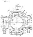
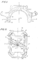
- FIG. 1 and 2 there is shown a complete segmented coupling for pipes in an assembled condition of the coupling, and, in the form it will be supplied for subsequent disassembly and assembly onto the grooved ends of the pipes (not shown).
- the segmented coupling is comprised of an upper coupling segment 10, a lower coupling segment 12, and a flow controller sub-assembly in the form of a butterfly valve which is indicated generally at 14.
- the respective coupling segments each are provided with keys 16 at their end faces for reception in grooves formed in the ends of pipes, the respective coupling segments being secured to each other by traction bolts 18 that are employed for tightening down the assembled coupling.
- sealing gaskets 20 Located within the assembled coupling are sealing gaskets 20 formed from an elastomeric material, the sealing gaskets each having axially directed portions for sealing engagement, respectively, with the exterior surface of a pipe, and, with the contained flow-controller sub-assembly 14.
- the flow-controller sub-assembly 14 in this embodiment is in the form of a butterfly valve, and, is comprised of a circular valve body 22 having bosses 24 extending diametrically thereof.
- the bosses 24 are to be received in socket openings 26 in the respective gasket segments 10 and 12, the respective bosses 22 providing a support for a rotatable spindle comprised of spindle portions 28 which are rigidly fixed to a butterfly valve 30.
- the butterfly valve is illustrated in a "closed” position, and is rotatable by the spindle 28 into an "open” position by rotating the butterfly valve about the Y-Y axis and towards or into coincidence with the Y,Z plane.
- Suitable bearings 32 and seals 34 are provided for the butterfly valves.
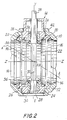
- the butterfly valve providing the flow-control sub-assembly 14 is shown separate from the coupling segments 10 and 12 in Figures 3-5.
- the cylindrical valve body 22 is formed by casting or forging as two body portions 22A, 22B, which are assembled to each other on opposite sides of the butterfly valve 30, which itself is provided as a casting or forging integral with the spindle portions 28.
- the body portions 22A, 22B of the cylindrical valve body 22 are then rigidly secured to each other by rivets 36, the required bearings 32 and seals 34 having been pre-assembled onto the spindle portions 28.
- the flow-control sub-assembly can provide different types of valves, such as a plug valve, or a ball valve by employing the same manner of construction.
- a standard configuration of the outer surfaces of the flow-control sub-assembly can be provided.
- interchangeability of any desired form of valve and the replacement of such valves can be accomplished using standard coupling segments that are identical in all respects one with the other.
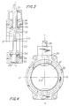
- the coupling segments 10 and 12 each have a semi-circular inner periphery adapting that coupling segment to be passed over the end of a pipe in a direction radially of the pipe axis.
- Tie respective coupling segments have bolting pads 40 having bolting faces for cooperation with either the head or the nut of a traction bolt 18, the bolting faces extending in a plane parallel to the X,Z plane of the coupling segment.
- Centrally of the coupling segment and arranged symmetrically around the Y-Y axis is a housing 42, which has internal surfaces configured to contain and locate a boss 24 of the flow-controller sub-assembly 14, the housing 42 providing the socket opening previously discussed.
- the respective opposite ends 44, 46 of the coupling segment are of identical configuration one with the other, but, reversed through 180° as viewed along the X-X axis. In this manner, any one end of any corresponding coupling segment will interfit with either end of an identical coupling segment.
- an end view of the coupling segment will be identical in all respects with that shown in Figure 8, and, the coupling segment will interfit with an identical coupling segment without regard to which of the end faces 44 and 46 of one of the coupling segments is presented to an end face 44 or an end face 46 of the other coupling segment.
- the respective end faces each include two end face portions 44A and 44B, or, 46A and 46B.
- the end face portions 44A and 44B extend in planes parallel to each other, and similarly, the end face portions 46A and 46B extend in planes parallel to each other but reversed in direction with respect to the X,Z plane of the coupling segment. If the coupling segments are to be symmetrical and identical in all respects, this relationship has to be preserved.
- the respective end face portions 44A, 44B and 46A, 46B are interconnected at their adjacent ends by a further end face portion 44C or 46C, thus providing a sawtooth formation of the end faces as viewed along the X-X axis.
- the intermediate end face portions 44C and 46C must be positioned either coincident with the X,Y plane, or, as is preferable, displaced to opposite sides of the X,Y plane. This arrangement of the intermediate end face portions must be duplicated in reverse at the opposite end of the coupling segment, for otherwise the coupling segment will become asymmetrical.
- the intermediate end face portions 44C and 46C can extend parallel to the X,Y plane, but preferably are arranged at an angle to that plane converging towards that plane in the direction of the Y+ axis.
- the respective end faces 44A, 44B and 46A, 46B must be linear in the direction of the Z-Z axis. They do not necessarily need to be linear in the direction of the X-X axis but preferably are so. Similar considerations apply to the intermediate end face portions 44C and 46C as related to the X,Y plane of the coupling segment.
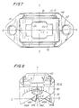
- this Figure shows the ends of two coupling segments when arranged in interfitted relation, this interfitted relation having been produced by rotating the coupling segment 10 180° about the Z-Z axis for it then to become the coupling segment 12.
- the end face portions 44A and 46A have become juxtaposed, and, the end face portions 44B and 46B have become juxtaposed, and, the intermediate end face portions 44C and 46C have become positioned in spaced parallel relation.
- the end face portions 44A, 44B and 46A,46B restrain the coupling segment 10 from movement in the Z- direction, and also restrain the coupling segment 12 from movement in the Z+ direction, any such movements producing interengagement of the respective end face portions 44A, 46A and 44B, 46B.
- the coupling segments 10 and 12 can only move in the opposite direction by the distance B existing between the intermediate end face portions 44C and 46C.
- the coupling segments when assembled to each other are limited in the extent of their permitted movement about the Y-Y axis.
- the respective coupling segments Upon tightening down of the traction bolts, the respective coupling segments are drawn towards each other into approximate coincidence with the X, Y plane, and, over-swinging of the respective ends of the coupling segments about the Y-Y axis is prevented.
- Such over-swinging of the ends of the respective coupling segments is to be avoided in that it can cause scuffing, distortion and dislocation of the seals 34 contained within the respective coupling segments, with consequential leakage at those seals in the finally assembled condition of the coupling.
- the coupling of the present invention can accommodate all deviations within the range of manufacturing tolerances in the pipe and the consequential variations in the dimensions of the grooves.
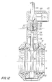
- That actuator includes a housing 50 provided with a cover 52.
- the housing 50 is secured to the boss 24 of the flow-controller sub-assembly in any convenient manner in encircling relation with the spindle 28.
- the actuator includes a shaft 54, that can be rotated by a hand wheel, electric motor or any other convenient means, the shaft 54 having a threaded stem 56 which extends through the threaded bore of a travelling nut 58.
- the travelling nut 58 has oppositely extending bails or trunnions 60 that respectively extend into axially straight grooves 62 formed within the housing 50.
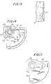
- a sleeve 64 Surrounding the nut 58 and rotatably supported within the housing 50 is a sleeve 64, the sleeve 64 having circumferentially extending slots providing scroll cams 66, as illustrated in Figure 13.
- the bales or trunnions will travel upwardly within the scroll cam slots 66, and in so doing, will cause the sleeve 64 to rotate.
- an indicator in the form of a pointer 68 is rigidly secured to the sleeve 64 and is journalled for rotation about the shaft 54.
- the indicator 68 slowly displaced between open and shut indications provided on the cover 52.
- this rotation of the sleeve 64 also can be utilized to actuate microswitiches 70 contained within the cover 52, the microswitches being operated by cam surfaces 72 on the sleeve 64. In this manner, an electrical signal can be provided to an indicator indicating the open or closed position of the butterfly valve 30.
Abstract
Description
- This invention relates to a segmented pipe coupling flow controller assembly assembled from coupling segments. Optionally, the coupling provides a "rigid" pipe coupling in the fully assembled condition of the coupling, or, a flexible pipe coupling.
- A "rigid" pipe coupling is one in which the segments of the pipe coupling are capable of moving relative to each other during tightening down of a coupling assembled from such coupling segments, to permit keys of the segments to come into rigid clamping engagement with grooves formed in the ends of pipes or the like.
- A "flexible" pipe coupling is one in which the end faces of the coupling segments engage each other prior to the coupling segments clamping down on the pipe exterior. This provides for limited movement of the pipe ends relative to each other.
- Throughout the discussion of this invention, reference is made to pipes, it being understood that one or other of the pipes, or both, can be provided by a nipple, a flanged coupling, or any other fitting incorporating a nipple construction.
- The invention finds particular utility in providing a segmented pipe coupling that incorporates a flow controller in the form of a butterfly valve, plug valve, ball valve or the like, as a sub-assembly insertable into the coupling segments prior to assembly of the pipe coupling.
- A flow controller assembly according to the features defined in the preamble of
claim 1 is known from FR-A-1581092. This teaches a pipe coupling comprising two pipe members, with inclined flanges and a groove at one end face of the pipe, a tubular rubber sleeve and two coupling segments. The rubber sleeve fits into the grooves of two mutually presented end faces of the pipes. The coupling segments are mounted on the rubber sleeve/pipe assembly with complementary grooves in the coupling segments fitting onto the inclined flanges of the pipes. Tightening of traction members in the coupling segments pushes the pipes together to form a sealing relationship with the rubber sleeve. Flow control means are provided by a valve within the coupling assembly made accessible via a spindle member extending through the rubber sleeve and a coupling segment. - According to the invention we provide a flow controller assembly in the form of a segmented pipe coupling, comprising
a complete flow-controller sub-assembly having a valve body, a valve seat provided within said valve body for cooperation with a rotatable valve member, a rotatable valve member supported within said body for rotation relative to said valve seat and into seating relation therewith, and means for rotating said valve member relative to said valve seat;
at least two coupling segments arranged in encircling relation with said valve body, said coupling segments having keys for reception in grooves in the ends of pipes; and
traction means for securing said coupling segments to each other in encircling relation with said pipe ends and said valve body;
at least one of said couplings segments providing access to said valve member rotating means from a position exterior of that coupling segment
characterised by a first gasket member axially separable from the valve body for forming a seal between the valve body and one pipe and a second separable gasket member also axially separable from the valve body, for forming a seal between the valve body and a second pipe at the opposite side of the valve body. - It would also be desirable to provide such a flow-controller in which the respective coupling segments retain their ability to rotate about the Y-Y axis of that coupling segment, but, to only a determined angular extent in order to provide either a rigid pipe coupling, or, a flexible pipe coupling.
- A further, preferred, aim is to provide a flow-controller that is insertable into the respective coupling segments at the time they are assembled into the segmented pipe coupling in order to provide an in-coupling flow-controller, which preferably is in the form of a butterfly valve, but which equally well could be in the form of a plug valve or ball valve, a butterfly valve being a hybrid form or a plug valve.
- Other preferred aspects of the present invention are set out in the sub claims.
- A preferred segmented pipe coupling of the present invention comprises coupling segments each having an end face at the opposite ends thereof the respective end faces of the coupling segments being oppositely inclined with respect to the X,Z plane of that coupling segment.
- The respective end faces each are comprised of first and second end face portions each inclined in the same direction relative to the X,Z plane, and, a third end face portion extending between the adjacent edges of the first and second end face portions at an angle to said first and second end face portions to provide a saw tooth configuration of the respective end faces in the direction of the Z-Z axis but inclined relative thereto.
- The third end face portion can extend in the X,Y plane of the coupling segment, but preferably is arranged at an acute positive angle relative thereto.
- In this manner, a pair of coupling segments when assembled into a segmented coupling are capable of moving in opposite directions relative to each other during tightening down of the segmented pipe coupling about the Y-Y axis of the respective coupling segments.
- Movement of the ends of the coupling segments and rotation of the coupling segments about their respective Y-Y axis will proceed under the influence of forces exerted during the tightening down of the coupling segment. Those forces will include a camming action between the respective juxtaposed end face portions as the respective coupling segments move towards each other in the radial direction of the pipe, and will include various other forces produced by traction bolts employed for securing the ends of the coupling segments to each other as produced during the tightening down of those traction bolts.
- The extent to which the coupling segments can move about the Y-Y axis will depend on the accuracy of formation of the pipe groove itself.
- Pipes vary in external diameter within a determined range of manufacturing tolerances, and, unless the pipe groove is lathe turned, the actual diameter of the axial wall of the pipe groove also will vary in dependence on those manufacturing tolerances. As the grooving of pipe ends commonly is performed in the field as opposed to a workshop, which renders lathe turning impractical, the common manner of grooving pipe ends is by the use of a grooving tool that employs the external surface of the pipe as the reference for the radial position of the axial wall of the pipe groove. Thus, due to the manner of formation of the groove, the radius of the axial wall of the groove will vary in direct relation to the manufacturing tolerances in the pipe itself.
- This raises limitations on the extent to which the X,Y plane of the respective coupling segments can be brought into coincidence with the X,Y plane of the pipe. Coincidence can be obtained at only one diameter of pipe groove. However, unless the pipe groove is lathe turned, the diameter of the pipe groove cannot be guaranteed and will vary within the range of manufacturing tolerances. As the disparity between the minimum and the maximum range of manufacturing tolerances is quite small, in all instances, the coupling segments will be moved into very closely approximate coincidence of their respective X,Y planes upon tightening down of the coupling, the coincidence being so closely approximate that it is of little consequence in the finally assembled segmented pipe coupling.
- It is particularly desired to ensure that any divergence of the X,Y plane of the coupling segments from the X,Y plane of the pipe is maintained within a determined range and that the Y-Y axis of the respective coupling segment remain in the X,Y plane of the pipe.
- Typically the respective coupling segments are configured for them to receive and contain a sub-assembly including a flow-controller that can be rotated between an open and a closed position by means of an actuating shaft assembly extending though the aperture of one of the coupling segments, the shaft being journalled at its other end in a bearing assembly that is received in the aperture of the diametrically opposite coupling segment.
- For all but the largest sizes of segmented pipe couplings, the pipe coupling usually comprises two coupling segments that interfit to provide a complete coupling. For larger sizes of coupling, the coupling can comprise more than two coupling segments. In such a coupling comprised of multiple coupling segments, the coupling segments each can remain identical one with the other. However, in such a construction it is more practical to provide identical diametrically opposite coupling segments an intermediate coupling segments in which the apertures do not exist.
- The flow-controller is in the form of a complete sub-assembly comprised of a body adapted to be received within and securely held by the coupling segments. The interior of the body can be configured in any manner compatible with its intended function. In the case of a butterfly valve, the body will be provided with a central aperture in which the butterfly valve is positioned and rotatable about the axis of the actuating shaft. The central aperture can be appropriately configured to accept either a plug valve or a ball valve, and, for it to provide the required seatings for those valves.
- Conveniently, an actuating mechanism is provided for the valve, the actuating mechanism being connected to the valve sub-assembly exteriorly of the assembled coupling either prior to or subsequent to tightening down of the coupling. Also, the above-mentioned sealing members (formed e.g from an elastomeric material) may be provided internally of the assembled coupling, and cooperate both with the coupling segments and with the contained valve flow-controller as well as with the pipe ends.
- As will be appreciated, the addition of the flow-controller sub-assembly to the segmented coupling will result in an increase in the width of the coupling in the direction of the Z,Z axis.
- In the absence of the saw tooth formation of the end faces of the coupling segments, this would limit the couplings to large diameter couplings, for example, of 100 mm [4 inches] I.D. or more.
- This is due to the fact that a planar surface passing through the X,Y,Z center of the coupling and which is inclined to the X,Z plane will emerge from the end faces of the coupling at a distance from the X,Z plane that progressively increases as the Z-Z length of the coupling is increased. However, as the arcuate extent of the coupling segments cannot exceed 180° if they are to pass onto a pipe, those portions of the coupling segments that extend beyond the pipe diameter must be formed as perpendiculars to the X,Z plane including the pipe axis.
- On the other hand, the angle of the end faces relative to the X,Z plane is required to be larger than the critical angle of frictional repose, which usually is in the order of 20°. If a coupling of only 25 mm [one inch] I.D. is to be provided, then, the coupling would then have to be considerably less than 45 mm [1.75 inches] in the Z-Z length, and, of approximately only 12.5 mm [0.5 inch] in the Z-Z length if the plane of separation of the coupling segments is to emerge at an acceptable position on the end faces of the coupling segments in which it is closely proximate to the X,Z plane.
- An added advantage of the saw tooth formation of the end faces is that by "folding" those faces by providing dual end face portions and an intermediate portion inclined thereto, they can be caused to exit the coupling at any desired position on the end face of the coupling, including the diametral X,Z plane of the coupling.
- Further, the saw tooth formation of the end faces may give an additional advantage in correcting the orientation of the respective coupling segments as they are assembled onto a pipe.
- Initially, the required seals are assembled onto the pipe. Then, one of the coupling segments and the flow-control sub-assembly is assembled onto the pipe. The other of the coupling segments is then assembled onto the pipe, this involving passing the said other coupling segment over the seals and over the flow-control sub-assembly.
- If misalignment of the seals or of the flow-control sub-assembly has occurred, this will cause mis-orientation of the said other coupling segment acting to force the said other coupling segment out of the X,Y plane of the coupling. However, the intermediate third end face portions then act to move the said other coupling segment into its required orientation, and, in turn move the seals and the flow-control sub-assembly into correct orientation with respect to the X,Y plane of the coupling.
- The invention will now be described with reference to the accompanying drawings which illustrates preferred embodiments thereof, and in which:
- Figure 1 is a front elevation of an assembled segmented pipe coupling with a flow-controller sub-assembly contained within the coupling;
- Figure 2 is a transverse cross-section taken on the line Z-Z of Figure 1;
- Figure 3 is a traverse cross-section corresponding with Figure 2 and showing the flow-controller sub-assembly alone;
- Figure 4 is a view corresponding with Figure 1 and showing the flow-controller sub-assembly alone;
- Figure 5 is a plan view of Figure 4;
- Figure 6 is a plan view of one of the coupling segments of Figure 1;
- Figure 7 is an underside plan view of the coupling segment of Figure 6;
- Figure 8 is an end elevation of the coupling segment of Figure 6;
- Figure 9 is a front elevation, partially in section, of the coupling section of Figure 6;
- Figure 10 is a cross-sectional view corresponding with Figure 2 showing the coupling segments in assembled condition, and, with the flow-controller sub-assembly removed;
- Figure 12 is a view corresponding with Figure 2, but showing a control mechanism attached to the flow-control sub-assembly;
- Figure 13 is a front elevation of a scroll cam incorporated into the control mechanism of Figure 11;
- Figure 14 is a plan view of the control mechanism of Figure 11 with a cover of that control removed; and,
- Figure 15 is a plan view of the control mechanism of Figure 11 with the cover in situ.
- Referring firstly to Figures 1 and 2, there is shown a complete segmented coupling for pipes in an assembled condition of the coupling, and, in the form it will be supplied for subsequent disassembly and assembly onto the grooved ends of the pipes (not shown).
- The segmented coupling is comprised of an
upper coupling segment 10, alower coupling segment 12, and a flow controller sub-assembly in the form of a butterfly valve which is indicated generally at 14. - The respective coupling segments each are provided with
keys 16 at their end faces for reception in grooves formed in the ends of pipes, the respective coupling segments being secured to each other bytraction bolts 18 that are employed for tightening down the assembled coupling. - Located within the assembled coupling are sealing
gaskets 20 formed from an elastomeric material, the sealing gaskets each having axially directed portions for sealing engagement, respectively, with the exterior surface of a pipe, and, with the contained flow-controller sub-assembly 14. - The flow-
controller sub-assembly 14 in this embodiment is in the form of a butterfly valve, and, is comprised of acircular valve body 22 havingbosses 24 extending diametrically thereof. Thebosses 24 are to be received insocket openings 26 in therespective gasket segments respective bosses 22 providing a support for a rotatable spindle comprised ofspindle portions 28 which are rigidly fixed to abutterfly valve 30. The butterfly valve is illustrated in a "closed" position, and is rotatable by thespindle 28 into an "open" position by rotating the butterfly valve about the Y-Y axis and towards or into coincidence with the Y,Z plane. Suitable bearings 32 and seals 34 are provided for the butterfly valves. - The butterfly valve providing the flow-
control sub-assembly 14 is shown separate from thecoupling segments - As a matter of convenience, the
cylindrical valve body 22 is formed by casting or forging as twobody portions butterfly valve 30, which itself is provided as a casting or forging integral with thespindle portions 28. Thebody portions cylindrical valve body 22 are then rigidly secured to each other byrivets 36, the required bearings 32 and seals 34 having been pre-assembled onto thespindle portions 28. - In this manner, a compact and relatively inexpensive butterfly valve construction is provided which readily can be removed from the coupling and replaced should servicing be necessary.
- As will be readily apparent, instead of providing a butterfly valve, the flow-control sub-assembly can provide different types of valves, such as a plug valve, or a ball valve by employing the same manner of construction.
- Without regard to the manner of configuration of the sealing surfaces of the flow-controller sub-assembly, a standard configuration of the outer surfaces of the flow-control sub-assembly can be provided. In this manner, interchangeability of any desired form of valve and the replacement of such valves can be accomplished using standard coupling segments that are identical in all respects one with the other.
- The formation of the coupling from identical coupling segments greatly reduces the manufacturing and warehousing costs, and also, eliminates the possibility of dissimilar coupling segments being incorrectly assembled one to the other.
- Referring now to Figures 6-10, a preferred configuration of the
respective coupling segments - As will be more clearly apparent from Figure 9, the
coupling segments bolting pads 40 having bolting faces for cooperation with either the head or the nut of atraction bolt 18, the bolting faces extending in a plane parallel to the X,Z plane of the coupling segment. Centrally of the coupling segment and arranged symmetrically around the Y-Y axis is ahousing 42, which has internal surfaces configured to contain and locate aboss 24 of the flow-controller sub-assembly 14, thehousing 42 providing the socket opening previously discussed. - The respective opposite ends 44, 46 of the coupling segment are of identical configuration one with the other, but, reversed through 180° as viewed along the X-X axis. In this manner, any one end of any corresponding coupling segment will interfit with either end of an identical coupling segment.
- The respective end faces each are inclined with respect to the X,Z plane of the coupling segment, but, in opposite directions relative to the X,Y plane as illustrated in Figure 8.
- Thus, upon rotation of the coupling segment about the Y-Y axis through 180°, an end view of the coupling segment will be identical in all respects with that shown in Figure 8, and, the coupling segment will interfit with an identical coupling segment without regard to which of the end faces 44 and 46 of one of the coupling segments is presented to an
end face 44 or an end face 46 of the other coupling segment. - As will be observed from Figure 8, if the coupling segment is rotated 180° about the Y-Y axis, then, the end face 46 becomes the
end face 44, and vice versa. - In a preferred embodiment of the invention, and for purposes that will be discussed later with respect to Figure 10, the respective end faces each include two
end face portions end face portions end face portions end face portions end face portion - The intermediate
end face portions end face portions - The respective end faces 44A, 44B and 46A, 46B must be linear in the direction of the Z-Z axis. They do not necessarily need to be linear in the direction of the X-X axis but preferably are so. Similar considerations apply to the intermediate
end face portions - Referring now to Figure 10, this Figure shows the ends of two coupling segments when arranged in interfitted relation, this interfitted relation having been produced by rotating the
coupling segment 10 180° about the Z-Z axis for it then to become thecoupling segment 12. In this interfitted relation of the end face portions, theend face portions end face portions end face portions - In this relationship, the
end face portions coupling segment 10 from movement in the Z- direction, and also restrain thecoupling segment 12 from movement in the Z+ direction, any such movements producing interengagement of the respectiveend face portions coupling segments end face portions end face portions - Upon tightening down of the traction bolts, the respective coupling segments are drawn towards each other into approximate coincidence with the X, Y plane, and, over-swinging of the respective ends of the coupling segments about the Y-Y axis is prevented. Such over-swinging of the ends of the respective coupling segments is to be avoided in that it can cause scuffing, distortion and dislocation of the
seals 34 contained within the respective coupling segments, with consequential leakage at those seals in the finally assembled condition of the coupling. The more the respective coupling segments are drawn towards each other, the greater will be the compressive stresses exerted on the contained gaskets, which are then highly susceptible to scuffing, distortion and dislocation in the event that over-swinging of the ends of the coupling segments should occur. - Over-swinging of the ends of the coupling segments is prevented by interengagement of the intermediate
end face portions end face portions - Referring now to Figures 12-15 an actuator for the flow-controller is illustrated. That actuator includes a
housing 50 provided with acover 52. Thehousing 50 is secured to theboss 24 of the flow-controller sub-assembly in any convenient manner in encircling relation with thespindle 28. - The actuator includes a
shaft 54, that can be rotated by a hand wheel, electric motor or any other convenient means, theshaft 54 having a threadedstem 56 which extends through the threaded bore of a travellingnut 58. The travellingnut 58 has oppositely extending bails ortrunnions 60 that respectively extend into axiallystraight grooves 62 formed within thehousing 50. Thus, on rotation of thespindle 54, thenut 58 will be caused to travel upwardly or downwardly within the axiallystraight grooves 62, depending on the direction of rotation of theshaft 54, in the absence of rotation of the nut. - Surrounding the
nut 58 and rotatably supported within thehousing 50 is asleeve 64, thesleeve 64 having circumferentially extending slots providingscroll cams 66, as illustrated in Figure 13. Thus, upon axial movement of thenut 58, the bales or trunnions will travel upwardly within thescroll cam slots 66, and in so doing, will cause thesleeve 64 to rotate. - In this manner, a slow-motion drive is provided to the
sleeve 64 requiring multiple turns of thespindle 54 to produce a 90° rotation of thesleeve 64. - As shown in Figures 12 and 15, an indicator in the form of a
pointer 68 is rigidly secured to thesleeve 64 and is journalled for rotation about theshaft 54. Thus, as thesleeve 64 slowly rotates, so will theindicator 68 slowly displaced between open and shut indications provided on thecover 52. - As illustrated in Figure 14, this rotation of the
sleeve 64 also can be utilized to actuatemicroswitiches 70 contained within thecover 52, the microswitches being operated bycam surfaces 72 on thesleeve 64. In this manner, an electrical signal can be provided to an indicator indicating the open or closed position of thebutterfly valve 30.
Claims (11)
- A flow-controller assembly in the form of a segmented pipe coupling, comprising
a complete flow-controller sub-assembly (14) having a valve body (22), a valve seat provided within said valve body (22) for co-operation with a rotatable valve member (30), a rotatable valve member (30) supported within said body (22) for rotation relative to said valve seat and into seating relation therewith, and means (28) for rotating said valve member (30) relative to said valve seat;
at least two coupling segments (10,12) arranged in encircling relation with said valve body (22), said coupling segments (10, 12) having keys (16) for reception in grooves in the ends of pipes; and
traction means (18) for securing said coupling segments (10,12) to each other in encircling relation with said pipe ends and said valve body (22);
at least one of said coupling segments (10,12) providing access to said valve member rotating means (28) from a position exterior of that coupling segment
characterised by a first gasket member (20) axially separable from the valve body (22) for forming a seal between the valve body (22) and one pipe and a second separable gasket member (20) also axially separable from the valve body (22), for forming a seal between the valve body (22) and a second pipe at the opposite side of the valve body (22). - The assembly of claim 1, in which said valve body (22) is a ring shaped member having bosses (24) extending diametrically thereof, said coupling segments each providing a housing for one of said bosses.
- The assembly of claim 2, in which said rotatable valve member (30) is supported for rotation by coaxially aligned shaft portions journalled for rotation within said bosses, at least one of said shaft portions extending to the exterior of the associated coupling segment and providing for rotation of said valve member.
- The assembly of claim 3, in which said valve member (30) is one of a butterfly valve, a plug valve, and a ball valve.
- The assembly of claim 1, including sealing members (34) interposed between said valve member and said valve body.
- The assembly of claim 1, in which said coupling segments (10,12) each include an end face at the respective opposite ends (44A,44B;46A,46B) of said coupling members, the end faces of each said coupling member being oppositely inclined with respect to an X,Z plane of that coupling member.
- The assembly of claim 6, in which said oppositely inclined end faces are each comprised of end face portions extending in parallel relation, and, an intermediate end face portion (44C,46C) interconnecting the adjacent ends of said respective end face portions.
- The assembly of claim 7, in which said intermediate end face portions are arranged at an acute angle to an X,Y plane of said coupling segment.
- The assembly of claim 1, including an actuator mechanism (50,52,54,58,62,64,66) connected to said valve body exteriorly of said coupling segments.
- The assembly of claim 9, in which said actuator mechanism includes a slow-motion rotary drive between said valve member rotating means and a drive shaft (54).
- The assembly of claim 10, in which said slow-motion rotary drive includes a rotatable sleeve (64) having circumferentially extending scroll cam slots (66), a drive nut (58) contained within said sleeve and having trunnions extending through said scroll cam slots and into axially straight guideways in a housing surrounding said sleeve, and, an axially fixed threaded shaft threadedly received within said notch, whereby rotation of said threaded shaft will produce axial movement of said nut, and in turn produce a slow motion rotary movement of said sleeve.
Applications Claiming Priority (2)
| Application Number | Priority Date | Filing Date | Title |
|---|---|---|---|
| US07/465,908 US5018704A (en) | 1990-01-12 | 1990-01-12 | Pipe coupling with in-coupling flow controller |
| US465908 | 1990-01-12 |
Publications (2)
| Publication Number | Publication Date |
|---|---|
| EP0437366A1 EP0437366A1 (en) | 1991-07-17 |
| EP0437366B1 true EP0437366B1 (en) | 1994-11-30 |
Family
ID=23849655
Family Applications (1)
| Application Number | Title | Priority Date | Filing Date |
|---|---|---|---|
| EP91300178A Expired - Lifetime EP0437366B1 (en) | 1990-01-12 | 1991-01-10 | Pipe coupling flow controller |
Country Status (9)
| Country | Link |
|---|---|
| US (1) | US5018704A (en) |
| EP (1) | EP0437366B1 (en) |
| AT (1) | ATE114795T1 (en) |
| AU (1) | AU652547B2 (en) |
| CA (1) | CA2033842C (en) |
| DE (1) | DE69105281T2 (en) |
| DK (1) | DK0437366T3 (en) |
| ES (1) | ES2068494T3 (en) |
| GR (1) | GR3014934T3 (en) |
Cited By (1)
| Publication number | Priority date | Publication date | Assignee | Title |
|---|---|---|---|---|
| CN102144116A (en) * | 2008-09-09 | 2011-08-03 | Nok株式会社 | Sealing device and method of mounting same |
Families Citing this family (10)
| Publication number | Priority date | Publication date | Assignee | Title |
|---|---|---|---|---|
| JP2651124B2 (en) * | 1994-10-14 | 1997-09-10 | 株式会社巴技術研究所 | Seat ring and butterfly valve fitted with the seat ring |
| IT236441Y1 (en) * | 1997-02-04 | 2000-08-17 | Tassalini Officina Meccanica S | THROTTLE |
| JP2006017005A (en) * | 2004-06-30 | 2006-01-19 | Denso Corp | Throttle device for internal combustion engine |
| US8403346B2 (en) * | 2005-01-20 | 2013-03-26 | Watson & Chalin Manufacturring, Inc. | Adjustable run height lift axle suspension system |
| US20080223450A1 (en) * | 2007-03-15 | 2008-09-18 | Aisan Kogyo Kabushiki Kaisha | Flow control valves |
| WO2010106369A2 (en) * | 2009-03-19 | 2010-09-23 | Coupling Technology Limited | Pipe coupling |
| SG10201604797QA (en) * | 2011-06-15 | 2016-08-30 | Amiad Water Systems Ltd | Tubular elements coupling |
| DK3350489T3 (en) * | 2015-09-18 | 2021-06-14 | Victaulic Co Of America | VALVE |
| BR112018008072B1 (en) * | 2015-11-23 | 2021-10-19 | Victaulic Company | VALVE, VALVE COUPLING, E, METHOD OF ASSEMBLY OF A VALVE |
| CA3197242A1 (en) | 2020-11-06 | 2022-05-12 | Victaulic Company | Coupling having rotation limited segments |
Family Cites Families (15)
| Publication number | Priority date | Publication date | Assignee | Title |
|---|---|---|---|---|
| US1978453A (en) * | 1933-06-05 | 1934-10-30 | Bernard C Flynn | Variable diameter gripping device |
| US2086001A (en) * | 1935-08-02 | 1937-07-06 | Wesley F Shaw | Valve |
| US2809011A (en) * | 1951-09-10 | 1957-10-08 | Davis David Goldberg | Valve structure having spherical seats |
| US2869221A (en) * | 1952-10-21 | 1959-01-20 | Stabl Armaturen G M B H | Method of producing valve housings |
| US3129920A (en) * | 1961-07-31 | 1964-04-21 | Crawford K Stillwagon | Conduit connection and valve |
| US3290003A (en) * | 1962-10-29 | 1966-12-06 | G & H Products Corp | Valve construction facilitating removal of parts |
| US3408096A (en) * | 1966-06-20 | 1968-10-29 | Inglis & Macinnes Ltd | Pipe coupling |
| GB1167375A (en) * | 1967-03-10 | 1969-10-15 | Frank Clifton | Improvements relating to Fluid Valves |
| GB1248734A (en) * | 1967-12-20 | 1971-10-06 | United Gas Industries Ltd | Improved shut-off valve |
| FR1581092A (en) * | 1968-07-17 | 1969-09-12 | ||
| US3722855A (en) * | 1971-07-14 | 1973-03-27 | Parker & Harper Mfg Co | Between flange valve assembly and clamping member |
| DE2324353A1 (en) * | 1973-05-14 | 1974-11-28 | Zero Manufacturing Co | THROTTLE FLAP VALVE |
| IT1145955B (en) * | 1981-03-20 | 1986-11-12 | Fip Formatura Inienzione Poli | MODULAR VALVE ACCORDING TO TWO ORTHOGONAL REACTIONS |
| US4350322A (en) * | 1981-08-31 | 1982-09-21 | Grove Truseal Valve Company | High torque plug valve actuator |
| DE3302159A1 (en) * | 1983-01-22 | 1984-07-26 | NEUMO Apparatebau, Metallgießerei GmbH, 7134 Knittlingen | THROTTLE VALVE |
-
1990
- 1990-01-12 US US07/465,908 patent/US5018704A/en not_active Expired - Fee Related
-
1991
- 1991-01-09 CA CA002033842A patent/CA2033842C/en not_active Expired - Fee Related
- 1991-01-10 AT AT91300178T patent/ATE114795T1/en not_active IP Right Cessation
- 1991-01-10 EP EP91300178A patent/EP0437366B1/en not_active Expired - Lifetime
- 1991-01-10 DK DK91300178.0T patent/DK0437366T3/en active
- 1991-01-10 ES ES91300178T patent/ES2068494T3/en not_active Expired - Lifetime
- 1991-01-10 DE DE69105281T patent/DE69105281T2/en not_active Expired - Fee Related
- 1991-01-14 AU AU69348/91A patent/AU652547B2/en not_active Ceased
-
1995
- 1995-02-01 GR GR950400198T patent/GR3014934T3/en unknown
Cited By (2)
| Publication number | Priority date | Publication date | Assignee | Title |
|---|---|---|---|---|
| CN102144116A (en) * | 2008-09-09 | 2011-08-03 | Nok株式会社 | Sealing device and method of mounting same |
| CN102144116B (en) * | 2008-09-09 | 2014-05-21 | Nok株式会社 | Sealing device and method of mounting same |
Also Published As
| Publication number | Publication date |
|---|---|
| AU652547B2 (en) | 1994-09-01 |
| CA2033842C (en) | 1994-10-04 |
| GR3014934T3 (en) | 1995-05-31 |
| AU6934891A (en) | 1991-07-18 |
| DE69105281D1 (en) | 1995-01-12 |
| DK0437366T3 (en) | 1995-04-03 |
| ES2068494T3 (en) | 1995-04-16 |
| CA2033842A1 (en) | 1991-07-13 |
| US5018704A (en) | 1991-05-28 |
| ATE114795T1 (en) | 1994-12-15 |
| DE69105281T2 (en) | 1995-06-01 |
| EP0437366A1 (en) | 1991-07-17 |
Similar Documents
| Publication | Publication Date | Title |
|---|---|---|
| US5018548A (en) | Segmented coupling for pipes | |
| EP0437366B1 (en) | Pipe coupling flow controller | |
| EP0888509B1 (en) | Rotary valve actuator and linkage | |
| GB2087517A (en) | Ball valve assembly | |
| US4586693A (en) | Shut-off apparatus | |
| EP0063857B1 (en) | Multi-component valve which can be assembled in a straight line or in an elbow configuration | |
| EP0774090B1 (en) | Valve assembly having improved valve seat | |
| JPH0445709B2 (en) | ||
| US4260129A (en) | Rotary spherical plug valve | |
| EP0786611B1 (en) | Ball segment valve | |
| US5333834A (en) | Valve driver | |
| US5388807A (en) | Modular butterfly valve | |
| CA1059495A (en) | Plug cock | |
| US4559843A (en) | Coupling member for mechanism for converting linear to rotary motion | |
| US4389037A (en) | Double disc gate vale with replaceable spacer ring | |
| US4683906A (en) | Trunnion type ball valve | |
| US3767162A (en) | Resilient connection between stem and plug of plug valve | |
| US4150694A (en) | Rotary plug valve | |
| GB2344152A (en) | Cylindrical plug valve seat | |
| US4621790A (en) | Butterfly valve | |
| CA1066259A (en) | Double disc gate valve with replaceable spacer ring | |
| US20070023727A1 (en) | Butterfly valve | |
| EP0461294B1 (en) | Stop valve | |
| KR100613882B1 (en) | Butterfly valve | |
| US4964435A (en) | Shuttle valve |
Legal Events
| Date | Code | Title | Description |
|---|---|---|---|
| PUAI | Public reference made under article 153(3) epc to a published international application that has entered the european phase |
Free format text: ORIGINAL CODE: 0009012 |
|
| AK | Designated contracting states |
Kind code of ref document: A1 Designated state(s): AT BE CH DE DK ES FR GB GR IT LI LU NL SE |
|
| 17P | Request for examination filed |
Effective date: 19911216 |
|
| 17Q | First examination report despatched |
Effective date: 19930819 |
|
| GRAA | (expected) grant |
Free format text: ORIGINAL CODE: 0009210 |
|
| AK | Designated contracting states |
Kind code of ref document: B1 Designated state(s): AT BE CH DE DK ES FR GB GR IT LI LU NL SE |
|
| REF | Corresponds to: |
Ref document number: 114795 Country of ref document: AT Date of ref document: 19941215 Kind code of ref document: T |
|
| REF | Corresponds to: |
Ref document number: 69105281 Country of ref document: DE Date of ref document: 19950112 |
|
| ITF | It: translation for a ep patent filed |
Owner name: MODIANO & ASSOCIATI S.R.L. |
|
| ET | Fr: translation filed | ||
| REG | Reference to a national code |
Ref country code: DK Ref legal event code: T3 |
|
| REG | Reference to a national code |
Ref country code: ES Ref legal event code: FG2A Ref document number: 2068494 Country of ref document: ES Kind code of ref document: T3 |
|
| REG | Reference to a national code |
Ref country code: GR Ref legal event code: FG4A Free format text: 3014934 |
|
| PLBE | No opposition filed within time limit |
Free format text: ORIGINAL CODE: 0009261 |
|
| STAA | Information on the status of an ep patent application or granted ep patent |
Free format text: STATUS: NO OPPOSITION FILED WITHIN TIME LIMIT |
|
| 26N | No opposition filed | ||
| PGFP | Annual fee paid to national office [announced via postgrant information from national office to epo] |
Ref country code: GB Payment date: 19981230 Year of fee payment: 9 |
|
| PGFP | Annual fee paid to national office [announced via postgrant information from national office to epo] |
Ref country code: ES Payment date: 19990108 Year of fee payment: 9 |
|
| PGFP | Annual fee paid to national office [announced via postgrant information from national office to epo] |
Ref country code: GR Payment date: 19990113 Year of fee payment: 9 |
|
| PGFP | Annual fee paid to national office [announced via postgrant information from national office to epo] |
Ref country code: FR Payment date: 19990115 Year of fee payment: 9 |
|
| PGFP | Annual fee paid to national office [announced via postgrant information from national office to epo] |
Ref country code: SE Payment date: 19990118 Year of fee payment: 9 |
|
| PGFP | Annual fee paid to national office [announced via postgrant information from national office to epo] |
Ref country code: LU Payment date: 19990121 Year of fee payment: 9 Ref country code: DE Payment date: 19990121 Year of fee payment: 9 Ref country code: AT Payment date: 19990121 Year of fee payment: 9 |
|
| PGFP | Annual fee paid to national office [announced via postgrant information from national office to epo] |
Ref country code: NL Payment date: 19990122 Year of fee payment: 9 |
|
| PGFP | Annual fee paid to national office [announced via postgrant information from national office to epo] |
Ref country code: DK Payment date: 19990125 Year of fee payment: 9 Ref country code: CH Payment date: 19990125 Year of fee payment: 9 |
|
| PGFP | Annual fee paid to national office [announced via postgrant information from national office to epo] |
Ref country code: BE Payment date: 19990127 Year of fee payment: 9 |
|
| PG25 | Lapsed in a contracting state [announced via postgrant information from national office to epo] |
Ref country code: LU Free format text: LAPSE BECAUSE OF NON-PAYMENT OF DUE FEES Effective date: 20000110 Ref country code: GB Free format text: LAPSE BECAUSE OF NON-PAYMENT OF DUE FEES Effective date: 20000110 Ref country code: DK Free format text: LAPSE BECAUSE OF NON-PAYMENT OF DUE FEES Effective date: 20000110 Ref country code: AT Free format text: LAPSE BECAUSE OF NON-PAYMENT OF DUE FEES Effective date: 20000110 |
|
| PG25 | Lapsed in a contracting state [announced via postgrant information from national office to epo] |
Ref country code: SE Free format text: LAPSE BECAUSE OF NON-PAYMENT OF DUE FEES Effective date: 20000111 Ref country code: ES Free format text: LAPSE BECAUSE OF NON-PAYMENT OF DUE FEES Effective date: 20000111 |
|
| PG25 | Lapsed in a contracting state [announced via postgrant information from national office to epo] |
Ref country code: LI Free format text: LAPSE BECAUSE OF NON-PAYMENT OF DUE FEES Effective date: 20000131 Ref country code: GR Free format text: LAPSE BECAUSE OF NON-PAYMENT OF DUE FEES Effective date: 20000131 Ref country code: CH Free format text: LAPSE BECAUSE OF NON-PAYMENT OF DUE FEES Effective date: 20000131 Ref country code: BE Free format text: LAPSE BECAUSE OF NON-PAYMENT OF DUE FEES Effective date: 20000131 |
|
| BERE | Be: lapsed |
Owner name: VICTAULIC CY OF AMERICA Effective date: 20000131 |
|
| PG25 | Lapsed in a contracting state [announced via postgrant information from national office to epo] |
Ref country code: NL Free format text: LAPSE BECAUSE OF NON-PAYMENT OF DUE FEES Effective date: 20000801 |
|
| GBPC | Gb: european patent ceased through non-payment of renewal fee |
Effective date: 20000110 |
|
| EUG | Se: european patent has lapsed |
Ref document number: 91300178.0 |
|
| REG | Reference to a national code |
Ref country code: CH Ref legal event code: PL |
|
| PG25 | Lapsed in a contracting state [announced via postgrant information from national office to epo] |
Ref country code: FR Free format text: LAPSE BECAUSE OF NON-PAYMENT OF DUE FEES Effective date: 20000929 |
|
| NLV4 | Nl: lapsed or anulled due to non-payment of the annual fee |
Effective date: 20000801 |
|
| REG | Reference to a national code |
Ref country code: DK Ref legal event code: EBP |
|
| PG25 | Lapsed in a contracting state [announced via postgrant information from national office to epo] |
Ref country code: DE Free format text: LAPSE BECAUSE OF NON-PAYMENT OF DUE FEES Effective date: 20001101 |
|
| REG | Reference to a national code |
Ref country code: FR Ref legal event code: ST |
|
| REG | Reference to a national code |
Ref country code: ES Ref legal event code: FD2A Effective date: 20011010 |
|
| PG25 | Lapsed in a contracting state [announced via postgrant information from national office to epo] |
Ref country code: IT Free format text: LAPSE BECAUSE OF NON-PAYMENT OF DUE FEES;WARNING: LAPSES OF ITALIAN PATENTS WITH EFFECTIVE DATE BEFORE 2007 MAY HAVE OCCURRED AT ANY TIME BEFORE 2007. THE CORRECT EFFECTIVE DATE MAY BE DIFFERENT FROM THE ONE RECORDED. Effective date: 20050110 |