EP0437261A2 - Pump with multi-port discharge - Google Patents
Pump with multi-port discharge Download PDFInfo
- Publication number
- EP0437261A2 EP0437261A2 EP91100262A EP91100262A EP0437261A2 EP 0437261 A2 EP0437261 A2 EP 0437261A2 EP 91100262 A EP91100262 A EP 91100262A EP 91100262 A EP91100262 A EP 91100262A EP 0437261 A2 EP0437261 A2 EP 0437261A2
- Authority
- EP
- European Patent Office
- Prior art keywords
- piston
- working chamber
- passages
- duct
- passage
- Prior art date
- Legal status (The legal status is an assumption and is not a legal conclusion. Google has not performed a legal analysis and makes no representation as to the accuracy of the status listed.)
- Granted
Links
Images


Classifications
-
- F—MECHANICAL ENGINEERING; LIGHTING; HEATING; WEAPONS; BLASTING
- F04—POSITIVE - DISPLACEMENT MACHINES FOR LIQUIDS; PUMPS FOR LIQUIDS OR ELASTIC FLUIDS
- F04B—POSITIVE-DISPLACEMENT MACHINES FOR LIQUIDS; PUMPS
- F04B7/00—Piston machines or pumps characterised by having positively-driven valving
- F04B7/04—Piston machines or pumps characterised by having positively-driven valving in which the valving is performed by pistons and cylinders coacting to open and close intake or outlet ports
- F04B7/06—Piston machines or pumps characterised by having positively-driven valving in which the valving is performed by pistons and cylinders coacting to open and close intake or outlet ports the pistons and cylinders being relatively reciprocated and rotated
-
- F—MECHANICAL ENGINEERING; LIGHTING; HEATING; WEAPONS; BLASTING
- F04—POSITIVE - DISPLACEMENT MACHINES FOR LIQUIDS; PUMPS FOR LIQUIDS OR ELASTIC FLUIDS
- F04B—POSITIVE-DISPLACEMENT MACHINES FOR LIQUIDS; PUMPS
- F04B13/00—Pumps specially modified to deliver fixed or variable measured quantities
- F04B13/02—Pumps specially modified to deliver fixed or variable measured quantities of two or more fluids at the same time
Definitions
- the field of the invention relates to metering pumps for pumping relatively precise volumes of fluid.
- Valveless, positive displacement metering pumps have been successfully employed in many applications where safe and accurate handling of fluids is required.
- the valveless pumping function is accomplished by the synchronous rotation and reciprocation of a piston in a precisely mated cylinder bore. One pressure and one suction stroke are completed per cycle.
- a duct (flat portion) on the piston connects a pair of cylinder ports alternately with the pumping chamber, i.e. one port on the pressure portion of the pumping cycle and the other on the suction cycle.
- the mechanically precise, free of random closure variation valving is performed by the piston duct motion.
- a pump head module containing the piston and cylinder is mounted in a manner that permits it to be swiveled angularly with respect to the rotating drive member. The degree of angle controls stroke length and in turn flow rate. The direction of the angle controls flow direction. This type of pump has been found to perform accurate transfers of both gaseous and liquid fluids.
- a valveless positive displacement pump including multiple ports is disclosed in U.S. Patent No. 4,008,003.
- the pump includes a cylinder divided into a pair of working chambers, each of the chambers communicating with two ports. In essence, the disclosed pump operates as two separate pumps.
- a valveless, positive displacement metering pump which includes a housing; a working chamber within the housing; first, second and third passages extending through the housing and adjoining the working chamber at first, second and third radial positions, respectively, a piston within the working chamber, the piston including a duct defined by its outer surface; means for oscillating the piston back and forth within the working chamber; and means for rotating the piston, the piston being positioned such that the duct is in sequential fluid communication with the first, second and third passages, respectively, as the piston is oscillated and rotated within the working chamber.
- the piston is also driven such that it is moving in a first axial direction when the duct is in fluid communication with one of the passages and the opposite axial direction when in fluid communication with each of the other two passages.
- a valveless, positive displacement metering pump 10 which includes at least three ports, two of which are used at any one time either as inlet or outlet ports while the other is used in an opposite manner.
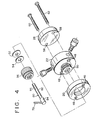
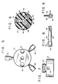
- the pump 10 includes a motor 12 including a drive shaft 14, an integral, hinged block 16, a flat, metal plate 18 secured to the motor housing and the block 16, a cylindrical spacer 20 adjoining the block 16, a cylindrical housing 22 which includes a cylindrical working chamber 24, and a cylindrical closure 26.
- the hinged block 16 is made from any suitable ductile material, such as DELRIN, an acetyl copolymer.
- the block includes a front portion 28 and a rear portion 30 connected by an integral hinge 32.
- the rear portion 30 includes a pair of threaded bores, while the front portion 28 includes a pair of unthreaded holes aligned with the threaded bores.
- First and second screws 34 extend through the respective holes and bores. By turning the screws, the angular orientation of the front portion 28 of the block may be changed with respect to the rear portion 30 as it moves about the integral hinge 32.
- the block 16 includes a large, cylindrical bore which extends completely through the rear portion 30 and terminates at a front wall 36 of a cylindrical projection 38 extending from the front portion 28.
- a smaller bore 40 extends through this wall 36.
- Two small, threaded bores 42 extend at least partially through the projection 38.
- the spacer 20 includes an axial bore 44 having about the same diameter as the above-mentioned bore 40, and a pair of unthreaded bores 46 extending therethrough.
- the axial bore 44 is aligned with the bore 40 through the front wall 36 of the projection 38 while the two smaller bores 46 are aligned, respectively, with the two small, threaded bores 42 within the projection 38.
- the housing 22 for the working chamber 24 includes a pair of bores 48 aligned with the bores 46 extending through the spacer. It is preferably made from a ceramic material such as carbon fiber reinforced polyphenylinesulfide, which is sold, for example, under the trade name RYTON.
- a threaded, cylindrical projection 50 formed integrally with the housing 22, extends rearwardly therefrom.
- the closure 26 includes a pair of bores 58 extending therethrough. These bores 58 are aligned with the bores 48 extending through the housing 22 of the working chamber 24.
- the closure includes a flat rear surface which adjoins the flat front surface of the housing 22. It accordingly seals one end of the working chamber 24.
- the housing and closure could be constructed as one piece, thereby obviating the need for a separate closure.
- a pair of screws 60,62 extend through the pairs of bores 58,48,46, respectively, and are threadably secured to the block 16 by means of the threaded bores 42.
- the closure 26, housing 22, spacer 20 and block 16 are secured, respectively, to each other by this pair of screws 60,62.
- Each of these elements is shown as having substantially the same outside diameters.
- the flat plate 18 is secured to the motor housing.
- a pair of screws 64 secure the plate 18 to the block 16.
- the front portion of the motor drive shaft 14 is secured to a cylindrical enclosure 66.
- the enclosure includes a cylindrical chamber 68 having an open front end. The rear end of the chamber is closed by a wall (not shown) through which the front portion of the drive shaft 14 extends.
- a lock screw 70 extends through a threaded bore 72 which extends through this wall, and bears against the drive shaft 14. The enclosure 66 accordingly rotates with the drive shaft when the motor 12 is actuated.
- a second, relatively larger bore 74 extends through the cylindrical enclosure 66 and communicates with the chamber 68 therein.
- a ball and socket fitting 76 is positioned within the bore 74.
- the ball member of this fitting includes a passage extending therethrough for receiving a connecting rod 78 of a piston assembly 80.
- the piston assembly which is best shown in Figs. 4,8 and 9, includes a cylindrical piston member 82, a cap 84 secured to the rear end of the piston member, the connecting rod 78 extending through the cap and piston member.
- the front end of the piston member 82 includes a longitudinal duct 86 extending from the end surface thereof to a selected point behind this end surface.
- the duct is preferably in the form of a channel including a flat bottom wall and a pair of side walls extending perpendicularly therefrom.
- a v-shaped channel would provide generally equivalent operating results, while a duct in the form of a flat might not allow adequate fluid flow in some instances.
- the housing 22 for the working chamber 24 is constructed so that the piston member 82 can rotate and reciprocate freely within the working chamber 24.
- the front end of the piston member is accordingly chamfered to facilitate such reciprocation.
- the clearance between the piston member and wall of the working chamber may be about one ten thousandth of an inch.
- the maximum length of the stroke of the piston member is such that the duct 86 is always entirely within the working chamber 24, and is substantially always in fluid communication with at least one of the three passages 88,90 communicating with the working chamber.
- one relatively large diameter passage 88 extends along a reference axis which is substantially vertical.
- Two smaller diameter passages 90 each extend at a forty-five degree angle with respect to the reference axis, and are therefore ninety degrees apart.
- the diameter of the relatively large passage 88 is twice the diameter of each smaller passage 90. The diameters of the passages would, of course, be adjusted if additional passages were employed.
- a piston member 82 having a quarter inch diameter is employed.
- the duct 86 within the piston member has a length of about three eights of an inch.
- the depth and width of the duct are about 0.093 inches.
- the channel accordingly traverses an axial distance of about forty-five degrees.
- the relatively large passage 88 has a diameter of about 0.177 inches while each of the smaller passages 90 in fluid communication with the working chamber 24 have diameters of about 0.089 inches.
- the axes of the three passages are substantially coplanar so that each will communicate with the duct 86 for a selected length of time as the piston assembly is rotated.
- Each passage communicates with a threaded bore 92 which extends between the outer surface of the housing 22 and an angular seating surface 94.
- a tube (not shown) having a conical fitting (not shown) secured to its end may be inserted with one of the threaded bores until the conical fitting contacts the seating surface 94.
- the conical fitting is maintained in place by a lock screw 96 which is engaged by the threaded bore. The lock screw presses the conical fitting against the seating surface 94 to provide a fluid-tight seal.
- the stroke of the piston assembly is adjusted by turning screws 34 to a position where the front portion 28 of the block 16 is at a selected angular orientation with respect to the second portion 30 thereof.
- the piston assembly will be caused to reciprocate upon rotation of the motor shaft 14 unless the front and rear portions of the block 16 are parallel to each other.
- the rotation of the motor shaft causes rotation of the cylinder 66 secured thereto.
- the piston assembly 80 being connected to the cylinder 66 by the fitting 76 and connecting rod 78, rotates about its axis at the same time it is caused to reciprocate.
- the housing 22 is oriented with respect to the block such that the piston member 82 will be moving in a first axial direction as the duct 86 communicates with the largest of the three passages and in an opposite direction as it moves into communication with the smaller passages 90.
- the piston assembly would move inwardly as the duct communicates with the larger passage. Suction would be created, and fluid would be drawn into the channel and working chamber.
- the smaller passages 90 would be sealed by the cylindrical outer surface of the piston member 82 during this phase. As the piston assembly would continue to rotate, it would eventually start moving in the opposite axial direction, i.e. towards the closure 26.
- the duct would communicate with one of the smaller passages, and then the other, during this pumping phase, thereby moving fluid from the working chamber, through the duct, and into the respective passages.
- the larger passage 88 would be closed at this time.
- the front portion 28 of the block 16 would simply have to be pivoted about the hinge 32 to an opposite angular orientation.
- the length and width of the duct 86, and the diameters and positions of the three passages 88,90 are constructed such that the duct is substantially always in fluid communication with one of the three passages regardless of the axial or rotational position of the piston assembly 80.
- the stroke of the piston assembly should be less than the length of the duct.
- While the pump shown in the figures includes only three passages which communicate with the duct and working chamber, it will be appreciated that additional passages may be provided at different radial positions to provide additional inflow or outflow capability. The diameters of the respective passages may also be modified if unequal flows are desired.
- the relatively large passage 88 is in fluid communication with the duct over about one hundred eighty degrees of rotation of the piston assembly 80.
- the second and third passages which have the same diameter, each communicate with the duct over about ninety degrees of rotation apiece.
- the piston member 82 moves in one axial direction as the duct communicates with the first passage 88. It moves in the opposite axial direction when communicating with the other two passages 90. Both the passages and the duct form relatively sharp corners with respect to the working chamber to insure the precise control of fluid flow within the pump.
Abstract
Description
- The field of the invention relates to metering pumps for pumping relatively precise volumes of fluid.
- Valveless, positive displacement metering pumps have been successfully employed in many applications where safe and accurate handling of fluids is required. The valveless pumping function is accomplished by the synchronous rotation and reciprocation of a piston in a precisely mated cylinder bore. One pressure and one suction stroke are completed per cycle. A duct (flat portion) on the piston connects a pair of cylinder ports alternately with the pumping chamber, i.e. one port on the pressure portion of the pumping cycle and the other on the suction cycle. The mechanically precise, free of random closure variation valving is performed by the piston duct motion. A pump head module containing the piston and cylinder is mounted in a manner that permits it to be swiveled angularly with respect to the rotating drive member. The degree of angle controls stroke length and in turn flow rate. The direction of the angle controls flow direction. This type of pump has been found to perform accurate transfers of both gaseous and liquid fluids.
- In some applications, it is necessary to provide two or more discharges of a fluid in selected proportions. This has typically been accomplished by using two separate pumps, or one pump and a multi-position flow diverter such as a solenoid valve.
- A valveless positive displacement pump including multiple ports is disclosed in U.S. Patent No. 4,008,003. The pump includes a cylinder divided into a pair of working chambers, each of the chambers communicating with two ports. In essence, the disclosed pump operates as two separate pumps.
- It is an object of the invention to provide a valveless, positive displacement metering pump including means for dividing the intake and/or discharge stroke into two or more parts.
- It is another object of the invention to provide a valveless, positive displacement metering pump capable of dispensing fluids at precise flow rates.
- In accordance with these and other objects of the invention, a valveless, positive displacement metering pump is provided which includes a housing; a working chamber within the housing; first, second and third passages extending through the housing and adjoining the working chamber at first, second and third radial positions, respectively, a piston within the working chamber, the piston including a duct defined by its outer surface; means for oscillating the piston back and forth within the working chamber; and means for rotating the piston, the piston being positioned such that the duct is in sequential fluid communication with the first, second and third passages, respectively, as the piston is oscillated and rotated within the working chamber. The piston is also driven such that it is moving in a first axial direction when the duct is in fluid communication with one of the passages and the opposite axial direction when in fluid communication with each of the other two passages.
-
- Fig. 1 is a front perspective view of a valveless, positive displacement metering pump according to the invention;
- Fig. 2 is a top plan view thereof;
- Fig. 3 is an exploded, front perspective view thereof;
- Fig. 4 is an exploded, rear perspective view of several elements of said pump;
- Fig. 5 is a front perspective view of a housing for a pump working chamber;
- Fig. 6 is a sectional, front elevation view thereof;
- Fig. 7 is a top plan view thereof;
- Fig. 8 is a side elevation view of a piston; and
- Fig. 9 is a front elevation view thereof.
- A valveless, positive
displacement metering pump 10 is provided which includes at least three ports, two of which are used at any one time either as inlet or outlet ports while the other is used in an opposite manner. - Referring to Figs. 1-3, the
pump 10 includes amotor 12 including adrive shaft 14, an integral, hingedblock 16, a flat,metal plate 18 secured to the motor housing and theblock 16, acylindrical spacer 20 adjoining theblock 16, acylindrical housing 22 which includes acylindrical working chamber 24, and acylindrical closure 26. - The hinged
block 16 is made from any suitable ductile material, such as DELRIN, an acetyl copolymer. The block includes afront portion 28 and arear portion 30 connected by anintegral hinge 32. Therear portion 30 includes a pair of threaded bores, while thefront portion 28 includes a pair of unthreaded holes aligned with the threaded bores. First andsecond screws 34 extend through the respective holes and bores. By turning the screws, the angular orientation of thefront portion 28 of the block may be changed with respect to therear portion 30 as it moves about theintegral hinge 32. - The
block 16 includes a large, cylindrical bore which extends completely through therear portion 30 and terminates at afront wall 36 of acylindrical projection 38 extending from thefront portion 28. Asmaller bore 40 extends through thiswall 36. Two small, threadedbores 42 extend at least partially through theprojection 38. - The
spacer 20 includes anaxial bore 44 having about the same diameter as the above-mentionedbore 40, and a pair ofunthreaded bores 46 extending therethrough. Theaxial bore 44 is aligned with thebore 40 through thefront wall 36 of theprojection 38 while the twosmaller bores 46 are aligned, respectively, with the two small, threadedbores 42 within theprojection 38. - The
housing 22 for theworking chamber 24 includes a pair ofbores 48 aligned with thebores 46 extending through the spacer. It is preferably made from a ceramic material such as carbon fiber reinforced polyphenylinesulfide, which is sold, for example, under the trade name RYTON. A threaded,cylindrical projection 50, formed integrally with thehousing 22, extends rearwardly therefrom. A pair ofwashers projection 50, and are maintained in place by agland nut 56. - The
closure 26 includes a pair ofbores 58 extending therethrough. Thesebores 58 are aligned with thebores 48 extending through thehousing 22 of theworking chamber 24. The closure includes a flat rear surface which adjoins the flat front surface of thehousing 22. It accordingly seals one end of theworking chamber 24. As an alternative, the housing and closure could be constructed as one piece, thereby obviating the need for a separate closure. A pair ofscrews bores block 16 by means of the threadedbores 42. Theclosure 26,housing 22,spacer 20 andblock 16 are secured, respectively, to each other by this pair ofscrews - As discussed above, the
flat plate 18 is secured to the motor housing. A pair ofscrews 64 secure theplate 18 to theblock 16. As shown in Fig. 3, the front portion of themotor drive shaft 14 is secured to acylindrical enclosure 66. The enclosure includes acylindrical chamber 68 having an open front end. The rear end of the chamber is closed by a wall (not shown) through which the front portion of thedrive shaft 14 extends. A lock screw 70 extends through a threadedbore 72 which extends through this wall, and bears against thedrive shaft 14. Theenclosure 66 accordingly rotates with the drive shaft when themotor 12 is actuated. - A second, relatively
larger bore 74 extends through thecylindrical enclosure 66 and communicates with thechamber 68 therein. A ball and socket fitting 76 is positioned within thebore 74. The ball member of this fitting includes a passage extending therethrough for receiving a connectingrod 78 of apiston assembly 80. The piston assembly, which is best shown in Figs. 4,8 and 9, includes acylindrical piston member 82, acap 84 secured to the rear end of the piston member, the connectingrod 78 extending through the cap and piston member. The front end of thepiston member 82 includes alongitudinal duct 86 extending from the end surface thereof to a selected point behind this end surface. The duct is preferably in the form of a channel including a flat bottom wall and a pair of side walls extending perpendicularly therefrom. A v-shaped channel would provide generally equivalent operating results, while a duct in the form of a flat might not allow adequate fluid flow in some instances. - Referring now to Figs. 4-7, the
housing 22 for the workingchamber 24 is constructed so that thepiston member 82 can rotate and reciprocate freely within the workingchamber 24. The front end of the piston member is accordingly chamfered to facilitate such reciprocation. The clearance between the piston member and wall of the working chamber may be about one ten thousandth of an inch. The maximum length of the stroke of the piston member is such that theduct 86 is always entirely within the workingchamber 24, and is substantially always in fluid communication with at least one of the threepassages - In the embodiment of the invention depicted in the drawings, three passages adjoin the working chamber. The diameters of the passages, axial position of the passages, and the width of the
duct 86 are all important in insuring that the proper flow rates into and out of the passages will be obtained. - As best shown in Fig. 6, one relatively
large diameter passage 88 extends along a reference axis which is substantially vertical. Twosmaller diameter passages 90 each extend at a forty-five degree angle with respect to the reference axis, and are therefore ninety degrees apart. The diameter of the relativelylarge passage 88 is twice the diameter of eachsmaller passage 90. The diameters of the passages would, of course, be adjusted if additional passages were employed. - In a particular embodiment of the invention, discussed here solely for explanatory purposes, a
piston member 82 having a quarter inch diameter is employed. Theduct 86 within the piston member has a length of about three eights of an inch. The depth and width of the duct are about 0.093 inches. The channel accordingly traverses an axial distance of about forty-five degrees. The relativelylarge passage 88 has a diameter of about 0.177 inches while each of thesmaller passages 90 in fluid communication with the workingchamber 24 have diameters of about 0.089 inches. The axes of the three passages are substantially coplanar so that each will communicate with theduct 86 for a selected length of time as the piston assembly is rotated. - Each passage communicates with a threaded
bore 92 which extends between the outer surface of thehousing 22 and anangular seating surface 94. A tube (not shown) having a conical fitting (not shown) secured to its end may be inserted with one of the threaded bores until the conical fitting contacts theseating surface 94. The conical fitting is maintained in place by alock screw 96 which is engaged by the threaded bore. The lock screw presses the conical fitting against theseating surface 94 to provide a fluid-tight seal. - In operation, the stroke of the piston assembly is adjusted by turning
screws 34 to a position where thefront portion 28 of theblock 16 is at a selected angular orientation with respect to thesecond portion 30 thereof. The piston assembly will be caused to reciprocate upon rotation of themotor shaft 14 unless the front and rear portions of theblock 16 are parallel to each other. When in the pumping mode, the rotation of the motor shaft causes rotation of thecylinder 66 secured thereto. Thepiston assembly 80, being connected to thecylinder 66 by the fitting 76 and connectingrod 78, rotates about its axis at the same time it is caused to reciprocate. The angular orientation of thefront portion 28 of the block, and therefore the workingchamber 24, with respect to therear portion 30 of the block, causes the rotation of the fitting 76, and therefore the piston assembly to be eccentric with respect to the working chamber. This causes the combined rotational and reciprocal motion of thepiston member 82 within the workingchamber 24. - The
housing 22 is oriented with respect to the block such that thepiston member 82 will be moving in a first axial direction as theduct 86 communicates with the largest of the three passages and in an opposite direction as it moves into communication with thesmaller passages 90. For example, if the relativelylarge passage 88 were to be used as an inflow passage, and the smaller passages were to be used for fluid outflow, the piston assembly would move inwardly as the duct communicates with the larger passage. Suction would be created, and fluid would be drawn into the channel and working chamber. Thesmaller passages 90 would be sealed by the cylindrical outer surface of thepiston member 82 during this phase. As the piston assembly would continue to rotate, it would eventually start moving in the opposite axial direction, i.e. towards theclosure 26. The duct would communicate with one of the smaller passages, and then the other, during this pumping phase, thereby moving fluid from the working chamber, through the duct, and into the respective passages. Thelarger passage 88 would be closed at this time. To reverse the action of the pump, thefront portion 28 of theblock 16 would simply have to be pivoted about thehinge 32 to an opposite angular orientation. - In order to avoid undue strain upon the pump, the length and width of the
duct 86, and the diameters and positions of the threepassages piston assembly 80. The stroke of the piston assembly should be less than the length of the duct. - While the pump shown in the figures includes only three passages which communicate with the duct and working chamber, it will be appreciated that additional passages may be provided at different radial positions to provide additional inflow or outflow capability. The diameters of the respective passages may also be modified if unequal flows are desired.
- In accordance with the pump as illustrated, the relatively
large passage 88 is in fluid communication with the duct over about one hundred eighty degrees of rotation of thepiston assembly 80. The second and third passages, which have the same diameter, each communicate with the duct over about ninety degrees of rotation apiece. Thepiston member 82 moves in one axial direction as the duct communicates with thefirst passage 88. It moves in the opposite axial direction when communicating with the other twopassages 90. Both the passages and the duct form relatively sharp corners with respect to the working chamber to insure the precise control of fluid flow within the pump. - Although illustrative embodiments of the present invention have been described herein with reference to the accompanying drawings, it is to be understood that the invention is not limited to those precise embodiments, and that various other changes and modifications may be effected therein by one skilled in the art without departing from the scope or spirit of the invention.
Claims (10)
- A valveless, positive displacement metering pump (10) comprising:
a housing (22);
a cylindrical working chamber (24) positioned within said housing;
a first passage (88) in fluid communication with said working chamber and extending through said housing;
a second passage (90) in fluid communication with said working chamber and extending through said housing;
a third passage (90) in fluid communication with said working chamber and extending through said housing;
said first, second and third passages adjoining said working chamber at first, second and third radial positions, respectively, with respect to the longitudinal axis of said working chamber;
a piston (80) positioned within said working chamber, said piston including a substantially cylindrical outer surface and a duct (86) defined by said outer surface;
means (66,78) for reciprocating said piston back and forth within said working chamber;
means (66,78) for rotating said piston as it is reciprocated such that said duct communicates sequentially with said second and third passages (90) while said piston is moving in a first axial direction and communicates with said first passage (88) while said piston is moving in a second axial direction opposite to said first axial direction. - A pump as described in claim 1 wherein said duct is in fluid communication with only one of said passages in substantially all rotational positions of said piston, said piston closing all but one of said passages in substantially all rotational positions of said piston.
- A pump as described in any of the preceding claims wherein said first, second and third passages adjoin said working chamber in substantially the same plane.
- A pump as described in any of the preceding claims wherein said first passage communicates with said duct over a larger range of rotation of said piston than either of said second or third passages.
- A pump as described in claim 4 wherein said first passage communicates with said duct over about one hundred eighty degrees of rotation of said piston.
- A pump as described in claim 5 wherein said second and third passages are in sequential fluid communication with said duct over about one hundred eighty degrees of rotation of said piston.
- A pump as described in any of the preceding claims wherein said duct is a channel defined wtihin said outer surface of said piston, said channel including a pair of opposing side walls.
- A method of pumping fluid, comprising the steps of:
providing a valveless, positive displacement metering pump (10) including a cylindrical working chamber (24), first, second and third passages (88,90,90) adjoining said working chamber at first, second and third radial positions, respectively, with respect to the longitudinal axis of the working chamber, and a piston (80) positioned within the working chamber, said piston including a substantially cylindrical outer surface and a duct (86) defined by said outer surface;
causing said piston to reciprocate in back and forth strokes within said working chamber; and
causing said piston to rotate as it is reciprocated such that said duct communicates sequentially with said second and third passages while the piston is moving in a first axial direction and communicates with said first passage while said piston is moving in a second axial direction opposite to said first axial direction. - A method as described in claim 8 wherein fluid is drawn into said working chamber through said first passage while said piston moves in said second axial direction, said fluid being pushed out of said working chamber through said second and third passages while said piston is moved in said first axial direction.
- A method as described in claim 8 wherein fluid is drawn into said working chamber through said second and third passages, respectively, as said piston is moved in said first axial direction, said fluid drawn in through said second passage mixing with said fluid drawn in through said third passage, said mixed fluid being pumped out through said first passage while said piston is moved in said second axial direction.
Applications Claiming Priority (2)
| Application Number | Priority Date | Filing Date | Title |
|---|---|---|---|
| US463260 | 1990-01-10 | ||
| US07/463,260 US5015157A (en) | 1990-01-10 | 1990-01-10 | Pump with multi-port discharge |
Publications (3)
| Publication Number | Publication Date |
|---|---|
| EP0437261A2 true EP0437261A2 (en) | 1991-07-17 |
| EP0437261A3 EP0437261A3 (en) | 1991-09-11 |
| EP0437261B1 EP0437261B1 (en) | 1994-04-20 |
Family
ID=23839484
Family Applications (1)
| Application Number | Title | Priority Date | Filing Date |
|---|---|---|---|
| EP91100262A Expired - Lifetime EP0437261B1 (en) | 1990-01-10 | 1991-01-10 | Pump with multi-port discharge |
Country Status (10)
| Country | Link |
|---|---|
| US (1) | US5015157A (en) |
| EP (1) | EP0437261B1 (en) |
| JP (1) | JPH0819897B2 (en) |
| KR (1) | KR0160947B1 (en) |
| AT (1) | ATE104745T1 (en) |
| CA (1) | CA2032240C (en) |
| DE (1) | DE69101716T2 (en) |
| DK (1) | DK0437261T3 (en) |
| ES (1) | ES2055927T3 (en) |
| FI (1) | FI100735B (en) |
Families Citing this family (35)
| Publication number | Priority date | Publication date | Assignee | Title |
|---|---|---|---|---|
| AU1425292A (en) * | 1991-01-31 | 1993-09-01 | Abbott Laboratories | Valveless metering pump with reciprocating, rotating piston |
| US5246354A (en) * | 1991-01-31 | 1993-09-21 | Abbott Laboratories | Valveless metering pump with reciprocating, rotating piston |
| US5299446A (en) * | 1991-06-28 | 1994-04-05 | Abbott Laboratories | Method and apparatus for calibrating a multiple port pump |
| US5312233A (en) * | 1992-02-25 | 1994-05-17 | Ivek Corporation | Linear liquid dispensing pump for dispensing liquid in nanoliter volumes |
| US5482448A (en) * | 1994-06-10 | 1996-01-09 | Atwater; Richard G. | Positive displacement pump with concentrically arranged reciprocating-rotating pistons |
| US5656499A (en) * | 1994-08-01 | 1997-08-12 | Abbott Laboratories | Method for performing automated hematology and cytometry analysis |
| US5631165A (en) * | 1994-08-01 | 1997-05-20 | Abbott Laboratories | Method for performing automated hematology and cytometry analysis |
| US5891734A (en) * | 1994-08-01 | 1999-04-06 | Abbott Laboratories | Method for performing automated analysis |
| US5741126A (en) * | 1996-03-01 | 1998-04-21 | Stearns; Stanley D. | Valveless metering pump with crisscrossed passage ways in the piston |
| US5795784A (en) | 1996-09-19 | 1998-08-18 | Abbott Laboratories | Method of performing a process for determining an item of interest in a sample |
| US5856194A (en) | 1996-09-19 | 1999-01-05 | Abbott Laboratories | Method for determination of item of interest in a sample |
| US5961303A (en) * | 1997-11-18 | 1999-10-05 | King; Kenyon M. | Positive displacement dispensing pump system |
| US6203974B1 (en) | 1998-09-03 | 2001-03-20 | Abbott Laboratories | Chemiluminescent immunoassay for detection of antibodies to various viruses |
| US6358237B1 (en) | 1999-01-19 | 2002-03-19 | Assistive Technology Products, Inc. | Methods and apparatus for delivering fluids to a patient |
| US6224347B1 (en) | 1999-09-13 | 2001-05-01 | The Gorman-Rupp Company | Low volume, high precision, positive displacement pump |
| US6398513B1 (en) | 2000-09-20 | 2002-06-04 | Fluid Management, Inc. | Fluid dispensers |
| US20020107501A1 (en) * | 2001-02-02 | 2002-08-08 | Smith James E. | Weight dependent, automatic filling dosage system and method of using same |
| US7125520B2 (en) * | 2001-04-25 | 2006-10-24 | Oyster Bay Pump Works, Inc. | Reagent addition system and method |
| US20040241023A1 (en) * | 2003-05-27 | 2004-12-02 | Pinkerton Harry E. | Positive displacement pump having piston and/or liner with vapor deposited polymer surface |
| EP1557564B1 (en) * | 2004-01-23 | 2008-07-16 | Sraosha Consulting, Inc | Reversible pump for driving hydraulic cylinders |
| US7785084B1 (en) | 2004-09-16 | 2010-08-31 | Fluid Metering, Inc. | Method and apparatus for elimination of gases in pump feed/injection equipment |
| US7387502B1 (en) | 2004-09-16 | 2008-06-17 | Fluid Metering, Inc. | Method and apparatus for elimination of gases in pump feed/injection equipment |
| US8562310B1 (en) | 2004-09-16 | 2013-10-22 | Fluid Metering, Inc. | Chlorination system with corrosion minimizing components |
| US20080187449A1 (en) * | 2007-02-02 | 2008-08-07 | Tetra Laval Holdings & Finance Sa | Pump system with integrated piston-valve actuation |
| US20090157219A1 (en) * | 2007-05-03 | 2009-06-18 | Parker Jr Lance T | Intelligent Sleeve Container for Use in a Controlled Syringe System |
| EP2222957B1 (en) | 2007-12-10 | 2017-01-25 | Bayer Healthcare LLC | Continuous fluid delivery system and method |
| WO2009120692A2 (en) * | 2008-03-25 | 2009-10-01 | Animal Innovations, Inc. | Syringe mechanism for detecting syringe status |
| WO2010126622A1 (en) * | 2009-04-27 | 2010-11-04 | Animal Innovations, Inc. | Injection syringe plunger valve assembly |
| US8864475B2 (en) * | 2009-05-28 | 2014-10-21 | Ivek Corporation | Pump with wash flow path for washing displacement piston and seal |
| US9261085B2 (en) | 2011-06-10 | 2016-02-16 | Fluid Metering, Inc. | Fluid pump having liquid reservoir and modified pressure relief slot |
| US20140231549A1 (en) * | 2011-09-28 | 2014-08-21 | Sensile Pat Ag | Fluid dispensing system |
| US10935021B2 (en) | 2013-12-13 | 2021-03-02 | Fluid Metering, Inc. | Mechanism for coarse and fine adjustment of flows in fixed displacement pump |
| WO2015089355A1 (en) * | 2013-12-13 | 2015-06-18 | Fluid Metering, Inc. | Mechanism for fine adjustment of flows in fixed displacement pump |
| CN104391403A (en) * | 2014-12-05 | 2015-03-04 | 京东方科技集团股份有限公司 | Liquid crystal pump and dropping method thereof |
| AU2016205275B2 (en) | 2015-01-09 | 2020-11-12 | Bayer Healthcare Llc | Multiple fluid delivery system with multi-use disposable set and features thereof |
Citations (6)
| Publication number | Priority date | Publication date | Assignee | Title |
|---|---|---|---|---|
| US1843733A (en) * | 1929-07-13 | 1932-02-02 | Hudson Motor Car Co | Oil pump |
| US3172362A (en) * | 1962-11-21 | 1965-03-09 | Philip L Sawyer | Fuel injection pump |
| GB1375801A (en) * | 1972-01-07 | 1974-11-27 | ||
| US4008003A (en) * | 1975-06-27 | 1977-02-15 | Pinkerton Harry E | Valveless positive displacement pump |
| US4043711A (en) * | 1975-04-24 | 1977-08-23 | Mikuni Kogyo Kabushiki Kaisha | Lubricating oil pump |
| US4479759A (en) * | 1979-12-13 | 1984-10-30 | Vernon Zeitz | Valveless, positive displacement pump |
Family Cites Families (5)
| Publication number | Priority date | Publication date | Assignee | Title |
|---|---|---|---|---|
| US3083895A (en) * | 1961-02-28 | 1963-04-02 | Besly Welles Corp | Compressor |
| US3168872A (en) * | 1963-01-23 | 1965-02-09 | Harry E Pinkerton | Positive displacement piston pump |
| JPS5271702A (en) * | 1975-12-12 | 1977-06-15 | Hiroaki Hideyoshi | Fixed delivery pumps for mixing multiple liquid components |
| JPS52136182A (en) * | 1976-05-07 | 1977-11-14 | Ogawa Koryo Kk | Production of pyradine compound |
| JPS5687318A (en) * | 1979-12-18 | 1981-07-15 | Toshiba Corp | Finely movable table |
-
1990
- 1990-01-10 US US07/463,260 patent/US5015157A/en not_active Expired - Lifetime
- 1990-12-27 CA CA002032240A patent/CA2032240C/en not_active Expired - Fee Related
-
1991
- 1991-01-08 KR KR1019910000160A patent/KR0160947B1/en not_active IP Right Cessation
- 1991-01-09 JP JP3011638A patent/JPH0819897B2/en not_active Expired - Fee Related
- 1991-01-09 FI FI910104A patent/FI100735B/en active
- 1991-01-10 AT AT9191100262T patent/ATE104745T1/en not_active IP Right Cessation
- 1991-01-10 EP EP91100262A patent/EP0437261B1/en not_active Expired - Lifetime
- 1991-01-10 DK DK91100262.4T patent/DK0437261T3/en active
- 1991-01-10 ES ES91100262T patent/ES2055927T3/en not_active Expired - Lifetime
- 1991-01-10 DE DE69101716T patent/DE69101716T2/en not_active Expired - Fee Related
Patent Citations (6)
| Publication number | Priority date | Publication date | Assignee | Title |
|---|---|---|---|---|
| US1843733A (en) * | 1929-07-13 | 1932-02-02 | Hudson Motor Car Co | Oil pump |
| US3172362A (en) * | 1962-11-21 | 1965-03-09 | Philip L Sawyer | Fuel injection pump |
| GB1375801A (en) * | 1972-01-07 | 1974-11-27 | ||
| US4043711A (en) * | 1975-04-24 | 1977-08-23 | Mikuni Kogyo Kabushiki Kaisha | Lubricating oil pump |
| US4008003A (en) * | 1975-06-27 | 1977-02-15 | Pinkerton Harry E | Valveless positive displacement pump |
| US4479759A (en) * | 1979-12-13 | 1984-10-30 | Vernon Zeitz | Valveless, positive displacement pump |
Also Published As
| Publication number | Publication date |
|---|---|
| FI910104A0 (en) | 1991-01-09 |
| FI910104A (en) | 1991-07-11 |
| KR910014605A (en) | 1991-08-31 |
| US5015157A (en) | 1991-05-14 |
| CA2032240A1 (en) | 1991-07-11 |
| JPH04272485A (en) | 1992-09-29 |
| CA2032240C (en) | 1995-02-07 |
| DE69101716D1 (en) | 1994-05-26 |
| ATE104745T1 (en) | 1994-05-15 |
| JPH0819897B2 (en) | 1996-03-04 |
| ES2055927T3 (en) | 1994-09-01 |
| EP0437261B1 (en) | 1994-04-20 |
| FI100735B (en) | 1998-02-13 |
| EP0437261A3 (en) | 1991-09-11 |
| DE69101716T2 (en) | 1994-11-10 |
| DK0437261T3 (en) | 1994-05-16 |
| KR0160947B1 (en) | 1999-10-01 |
Similar Documents
| Publication | Publication Date | Title |
|---|---|---|
| EP0437261B1 (en) | Pump with multi-port discharge | |
| US5044889A (en) | Phase adjustable metering pump, and method of adjusting the flow rate thereof | |
| US5020980A (en) | Valveless, positive displacement pump including hinge for angular adjustment | |
| US5092037A (en) | Method of making a valveless positive displacement pump including a living hinge for angular adjustment | |
| US5863187A (en) | Two position rotary reciprocating pump with liquid displacement flow adjustment | |
| EP0248110A2 (en) | Valveless positive displacement metering pump | |
| EP2087239B1 (en) | Metering and pumping devices | |
| US4479759A (en) | Valveless, positive displacement pump | |
| US5741126A (en) | Valveless metering pump with crisscrossed passage ways in the piston | |
| JPH02230976A (en) | Double acting piston pump | |
| CA2213194A1 (en) | Multiple piston pump | |
| JP3314186B1 (en) | Fluid suction and discharge device | |
| US7217105B2 (en) | Integrated pump and wash pump | |
| US7080975B2 (en) | Integrated pump and ceramic valve | |
| US7214039B2 (en) | Integrated ratio pump and check valve apparatus | |
| US4946355A (en) | Orbital pump | |
| JPH07208325A (en) | No-valve reciprocation piston pump | |
| JP2006063850A (en) | Reversible valveless pump | |
| KR20020052143A (en) | The suction and discharging device of the flow mass | |
| PL161189B1 (en) | Metering pump |
Legal Events
| Date | Code | Title | Description |
|---|---|---|---|
| PUAI | Public reference made under article 153(3) epc to a published international application that has entered the european phase |
Free format text: ORIGINAL CODE: 0009012 |
|
| AK | Designated contracting states |
Kind code of ref document: A2 Designated state(s): AT BE CH DE DK ES FR GB GR IT LI LU NL SE |
|
| PUAL | Search report despatched |
Free format text: ORIGINAL CODE: 0009013 |
|
| AK | Designated contracting states |
Kind code of ref document: A3 Designated state(s): AT BE CH DE DK ES FR GB GR IT LI LU NL SE |
|
| 17P | Request for examination filed |
Effective date: 19920214 |
|
| 17Q | First examination report despatched |
Effective date: 19920722 |
|
| GRAA | (expected) grant |
Free format text: ORIGINAL CODE: 0009210 |
|
| AK | Designated contracting states |
Kind code of ref document: B1 Designated state(s): AT BE CH DE DK ES FR GB GR IT LI LU NL SE |
|
| PG25 | Lapsed in a contracting state [announced via postgrant information from national office to epo] |
Ref country code: GR Free format text: LAPSE BECAUSE OF FAILURE TO SUBMIT A TRANSLATION OF THE DESCRIPTION OR TO PAY THE FEE WITHIN THE PRESCRIBED TIME-LIMIT Effective date: 19940420 |
|
| REF | Corresponds to: |
Ref document number: 104745 Country of ref document: AT Date of ref document: 19940515 Kind code of ref document: T |
|
| REG | Reference to a national code |
Ref country code: DK Ref legal event code: T3 |
|
| REF | Corresponds to: |
Ref document number: 69101716 Country of ref document: DE Date of ref document: 19940526 |
|
| ET | Fr: translation filed | ||
| ITF | It: translation for a ep patent filed |
Owner name: UFFICIO BREVETTI RICCARDI & C. |
|
| REG | Reference to a national code |
Ref country code: ES Ref legal event code: FG2A Ref document number: 2055927 Country of ref document: ES Kind code of ref document: T3 |
|
| EAL | Se: european patent in force in sweden |
Ref document number: 91100262.4 |
|
| PG25 | Lapsed in a contracting state [announced via postgrant information from national office to epo] |
Ref country code: LU Free format text: LAPSE BECAUSE OF NON-PAYMENT OF DUE FEES Effective date: 19950131 |
|
| PLBE | No opposition filed within time limit |
Free format text: ORIGINAL CODE: 0009261 |
|
| STAA | Information on the status of an ep patent application or granted ep patent |
Free format text: STATUS: NO OPPOSITION FILED WITHIN TIME LIMIT |
|
| 26N | No opposition filed | ||
| REG | Reference to a national code |
Ref country code: FR Ref legal event code: TP |
|
| BECA | Be: change of holder's address |
Free format text: 980331 *ROPER HOLDINGS INC.;*JAEKEL ROBERT WILLIAM;*PARDINAS GUILLERMO PEDRO:300 DELAWARE AVENUE, SUITE 1704, WILMINGTON, DELAWARE 19801;1233 YORKSHIRE LANE, BARRINGTON ILLINOIS (US);11091 SW 61 TERR., MIAMI FLORIDA (US) |
|
| BECH | Be: change of holder |
Free format text: 980331 *ROPER HOLDINGS INC.;*JAEKEL ROBERT WILLIAM;*PARDINAS GUILLERMO PEDRO:300 DELAWARE AVENUE, SUITE 1704, WILMINGTON, DELAWARE 19801;1233 YORKSHIRE LANE, BARRINGTON ILLINOIS (US);11091 SW 61 TERR., MIAMI FLORIDA (US) |
|
| REG | Reference to a national code |
Ref country code: GB Ref legal event code: IF02 |
|
| PGFP | Annual fee paid to national office [announced via postgrant information from national office to epo] |
Ref country code: SE Payment date: 20020107 Year of fee payment: 12 |
|
| PGFP | Annual fee paid to national office [announced via postgrant information from national office to epo] |
Ref country code: GB Payment date: 20020109 Year of fee payment: 12 |
|
| PGFP | Annual fee paid to national office [announced via postgrant information from national office to epo] |
Ref country code: FR Payment date: 20020110 Year of fee payment: 12 |
|
| PGFP | Annual fee paid to national office [announced via postgrant information from national office to epo] |
Ref country code: DK Payment date: 20020111 Year of fee payment: 12 Ref country code: AT Payment date: 20020111 Year of fee payment: 12 |
|
| PGFP | Annual fee paid to national office [announced via postgrant information from national office to epo] |
Ref country code: ES Payment date: 20020130 Year of fee payment: 12 |
|
| PGFP | Annual fee paid to national office [announced via postgrant information from national office to epo] |
Ref country code: NL Payment date: 20020131 Year of fee payment: 12 Ref country code: CH Payment date: 20020131 Year of fee payment: 12 |
|
| PGFP | Annual fee paid to national office [announced via postgrant information from national office to epo] |
Ref country code: DE Payment date: 20020212 Year of fee payment: 12 |
|
| PGFP | Annual fee paid to national office [announced via postgrant information from national office to epo] |
Ref country code: BE Payment date: 20020320 Year of fee payment: 12 |
|
| PG25 | Lapsed in a contracting state [announced via postgrant information from national office to epo] |
Ref country code: GB Free format text: LAPSE BECAUSE OF NON-PAYMENT OF DUE FEES Effective date: 20030110 Ref country code: AT Free format text: LAPSE BECAUSE OF NON-PAYMENT OF DUE FEES Effective date: 20030110 |
|
| PG25 | Lapsed in a contracting state [announced via postgrant information from national office to epo] |
Ref country code: SE Free format text: LAPSE BECAUSE OF NON-PAYMENT OF DUE FEES Effective date: 20030111 Ref country code: ES Free format text: LAPSE BECAUSE OF NON-PAYMENT OF DUE FEES Effective date: 20030111 |
|
| PG25 | Lapsed in a contracting state [announced via postgrant information from national office to epo] |
Ref country code: LI Free format text: LAPSE BECAUSE OF NON-PAYMENT OF DUE FEES Effective date: 20030131 Ref country code: DK Free format text: LAPSE BECAUSE OF NON-PAYMENT OF DUE FEES Effective date: 20030131 Ref country code: CH Free format text: LAPSE BECAUSE OF NON-PAYMENT OF DUE FEES Effective date: 20030131 Ref country code: BE Free format text: LAPSE BECAUSE OF NON-PAYMENT OF DUE FEES Effective date: 20030131 |
|
| PG25 | Lapsed in a contracting state [announced via postgrant information from national office to epo] |
Ref country code: NL Free format text: LAPSE BECAUSE OF NON-PAYMENT OF DUE FEES Effective date: 20030801 Ref country code: DE Free format text: LAPSE BECAUSE OF NON-PAYMENT OF DUE FEES Effective date: 20030801 |
|
| GBPC | Gb: european patent ceased through non-payment of renewal fee |
Effective date: 20030110 |
|
| EUG | Se: european patent has lapsed | ||
| REG | Reference to a national code |
Ref country code: DK Ref legal event code: EBP |
|
| REG | Reference to a national code |
Ref country code: CH Ref legal event code: PL |
|
| PG25 | Lapsed in a contracting state [announced via postgrant information from national office to epo] |
Ref country code: FR Free format text: LAPSE BECAUSE OF NON-PAYMENT OF DUE FEES Effective date: 20030930 |
|
| NLV4 | Nl: lapsed or anulled due to non-payment of the annual fee |
Effective date: 20030801 |
|
| REG | Reference to a national code |
Ref country code: FR Ref legal event code: ST |
|
| REG | Reference to a national code |
Ref country code: ES Ref legal event code: FD2A Effective date: 20030111 |
|
| PG25 | Lapsed in a contracting state [announced via postgrant information from national office to epo] |
Ref country code: IT Free format text: LAPSE BECAUSE OF NON-PAYMENT OF DUE FEES;WARNING: LAPSES OF ITALIAN PATENTS WITH EFFECTIVE DATE BEFORE 2007 MAY HAVE OCCURRED AT ANY TIME BEFORE 2007. THE CORRECT EFFECTIVE DATE MAY BE DIFFERENT FROM THE ONE RECORDED. Effective date: 20050110 |