EP0436759A1 - A system for treating waste material in a molten state - Google Patents
A system for treating waste material in a molten state Download PDFInfo
- Publication number
- EP0436759A1 EP0436759A1 EP90100518A EP90100518A EP0436759A1 EP 0436759 A1 EP0436759 A1 EP 0436759A1 EP 90100518 A EP90100518 A EP 90100518A EP 90100518 A EP90100518 A EP 90100518A EP 0436759 A1 EP0436759 A1 EP 0436759A1
- Authority
- EP
- European Patent Office
- Prior art keywords
- combustion furnace
- waste gas
- removing unit
- molten
- dust removing
- Prior art date
- Legal status (The legal status is an assumption and is not a legal conclusion. Google has not performed a legal analysis and makes no representation as to the accuracy of the status listed.)
- Granted
Links
Images


Classifications
-
- F—MECHANICAL ENGINEERING; LIGHTING; HEATING; WEAPONS; BLASTING
- F23—COMBUSTION APPARATUS; COMBUSTION PROCESSES
- F23J—REMOVAL OR TREATMENT OF COMBUSTION PRODUCTS OR COMBUSTION RESIDUES; FLUES
- F23J15/00—Arrangements of devices for treating smoke or fumes
- F23J15/02—Arrangements of devices for treating smoke or fumes of purifiers, e.g. for removing noxious material
- F23J15/022—Arrangements of devices for treating smoke or fumes of purifiers, e.g. for removing noxious material for removing solid particulate material from the gasflow
- F23J15/027—Arrangements of devices for treating smoke or fumes of purifiers, e.g. for removing noxious material for removing solid particulate material from the gasflow using cyclone separators
-
- F—MECHANICAL ENGINEERING; LIGHTING; HEATING; WEAPONS; BLASTING
- F23—COMBUSTION APPARATUS; COMBUSTION PROCESSES
- F23C—METHODS OR APPARATUS FOR COMBUSTION USING FLUID FUEL OR SOLID FUEL SUSPENDED IN A CARRIER GAS OR AIR
- F23C3/00—Combustion apparatus characterised by the shape of the combustion chamber
- F23C3/006—Combustion apparatus characterised by the shape of the combustion chamber the chamber being arranged for cyclonic combustion
- F23C3/008—Combustion apparatus characterised by the shape of the combustion chamber the chamber being arranged for cyclonic combustion for pulverulent fuel
-
- F—MECHANICAL ENGINEERING; LIGHTING; HEATING; WEAPONS; BLASTING
- F23—COMBUSTION APPARATUS; COMBUSTION PROCESSES
- F23G—CREMATION FURNACES; CONSUMING WASTE PRODUCTS BY COMBUSTION
- F23G5/00—Incineration of waste; Incinerator constructions; Details, accessories or control therefor
- F23G5/006—General arrangement of incineration plant, e.g. flow sheets
-
- F—MECHANICAL ENGINEERING; LIGHTING; HEATING; WEAPONS; BLASTING
- F23—COMBUSTION APPARATUS; COMBUSTION PROCESSES
- F23G—CREMATION FURNACES; CONSUMING WASTE PRODUCTS BY COMBUSTION
- F23G5/00—Incineration of waste; Incinerator constructions; Details, accessories or control therefor
- F23G5/08—Incineration of waste; Incinerator constructions; Details, accessories or control therefor having supplementary heating
- F23G5/085—High-temperature heating means, e.g. plasma, for partly melting the waste
-
- F—MECHANICAL ENGINEERING; LIGHTING; HEATING; WEAPONS; BLASTING
- F23—COMBUSTION APPARATUS; COMBUSTION PROCESSES
- F23G—CREMATION FURNACES; CONSUMING WASTE PRODUCTS BY COMBUSTION
- F23G5/00—Incineration of waste; Incinerator constructions; Details, accessories or control therefor
- F23G5/08—Incineration of waste; Incinerator constructions; Details, accessories or control therefor having supplementary heating
- F23G5/14—Incineration of waste; Incinerator constructions; Details, accessories or control therefor having supplementary heating including secondary combustion
- F23G5/16—Incineration of waste; Incinerator constructions; Details, accessories or control therefor having supplementary heating including secondary combustion in a separate combustion chamber
-
- F—MECHANICAL ENGINEERING; LIGHTING; HEATING; WEAPONS; BLASTING
- F23—COMBUSTION APPARATUS; COMBUSTION PROCESSES
- F23G—CREMATION FURNACES; CONSUMING WASTE PRODUCTS BY COMBUSTION
- F23G5/00—Incineration of waste; Incinerator constructions; Details, accessories or control therefor
- F23G5/32—Incineration of waste; Incinerator constructions; Details, accessories or control therefor the waste being subjected to a whirling movement, e.g. cyclonic incinerators
-
- F—MECHANICAL ENGINEERING; LIGHTING; HEATING; WEAPONS; BLASTING
- F23—COMBUSTION APPARATUS; COMBUSTION PROCESSES
- F23G—CREMATION FURNACES; CONSUMING WASTE PRODUCTS BY COMBUSTION
- F23G5/00—Incineration of waste; Incinerator constructions; Details, accessories or control therefor
- F23G5/44—Details; Accessories
- F23G5/46—Recuperation of heat
-
- F—MECHANICAL ENGINEERING; LIGHTING; HEATING; WEAPONS; BLASTING
- F23—COMBUSTION APPARATUS; COMBUSTION PROCESSES
- F23J—REMOVAL OR TREATMENT OF COMBUSTION PRODUCTS OR COMBUSTION RESIDUES; FLUES
- F23J1/00—Removing ash, clinker, or slag from combustion chambers
- F23J1/08—Liquid slag removal
-
- F—MECHANICAL ENGINEERING; LIGHTING; HEATING; WEAPONS; BLASTING
- F23—COMBUSTION APPARATUS; COMBUSTION PROCESSES
- F23G—CREMATION FURNACES; CONSUMING WASTE PRODUCTS BY COMBUSTION
- F23G2209/00—Specific waste
- F23G2209/12—Sludge, slurries or mixtures of liquids
Definitions
- the present invention relates generally to a system for treating waste material in a molten state. More particularly, the present invention relates to a system for treating in a molten state waste material such as pulverized combustible material, e.g., dried sludge derived from sewerage, pulverized coal or the like material each including incombustible material in such a manner that the combustible material is burned, the incombustible material is molten in a swirling flow state in a combustion furnace installed in an inclined state with a horizontal attitude and then the molten slag is taken from the combustion furnace to the outside of the system.
- waste material such as pulverized combustible material, e.g., dried sludge derived from sewerage, pulverized coal or the like material each including incombustible material in such a manner that the combustible material is burned, the incombustible material is molten in a swirling flow state in a combustion furnace installed
- the present invention relates a system for treating in a molten state fluid waste material such as dried sludge, pulverized coal, industrial waste liquid or the like material each including incombustible material in such a manner that the combustible material is burned, the incombustible material is molten in a combustion furnace, floatable dust carried by combustion waste gas to be discharged to the outside of the system is collected and molten in the high temperature atmosphere of a swirling flow in a dust removing unit installed in an inclined state with a horizontal attitude and the molten slag is collected and then taken from the combustion furnace to the outside of the system.
- a molten state fluid waste material such as dried sludge, pulverized coal, industrial waste liquid or the like material each including incombustible material in such a manner that the combustible material is burned, the incombustible material is molten in a combustion furnace, floatable dust carried by combustion waste gas to be discharged to the outside of the system is collected and
- a swirling flow type combustion furnace which is constructed such that pulverized combustible material such as dried sludge, pulverized coal or the like material each including incombustible material is injected into the interior of the cylindrical combustion furnace together with combustion gas from the end wall or the side wall of the combustion furnace while generating an intense swirling flow, the incombustible material, i.e., combustion ash is molten under the influence of thermal energy derived from combustion and the molten slag is discharged through an outlet port of the combustion furnace has been hitherto known (refer to, e.g., an official gazette of Japanese Laid-Open Patent NO. 213408/1986 (hereinafter referred to as "Prior Invention 1") and a specification of Japanese Patent Application NO. 4489/1987 (hereinafter referred to as "Prior Invention 2").
- a swirling flow type combustion furnace as disclosed in the Prior Invention 1 is constructed such that a cylindrical housing of the combustion furnace is installed in an inclined state by a predetermined inclination angle, a plurality of auxiliary burner each including a heavy oil feed pipe and a combustion air feed pipe are arranged on one end wall (end surface on the upstream side) of the combustion furnace, a cylindrical member including a waste gas outlet port on the upper side and a molten slag discharge port at the lower side is coupled to the other end wall (end surface on the downstream side) of the combustion furnace and a pulverized combustible material feed port and a combustion air inlet port are arranged at the upper part of the outer surface of the combustion furnace at positions in the vicinity of the end surface on the upstream side.
- Each of the auxiliary burners is designated in a concentrical doubled-layer structure comprising a heavy oil feed pipe and an air feed pipe, and a plurality of guide blades for generating a swirling flow are attached to the foremost end of each auxiliary burner.
- the Prior Invention 2 discloses a swirling flow type combustion furnace installed in an inclined state with a horizontal attitude wherein the combustion furnace comprises a primary combustion furnace and a secondary combustion furnace.
- the secondary combustion furnace is formed with a combustion air feed port at an intermediate zone through which oxygen required for combustion can be introduced into the interior of the combustion furnace.
- the combustion furnace is provided with an orifice-shaped baffle plate so that a part of the interior of the combustion furnace upstream of the baffle plate is divided into three sections, i.e., an upstream zone, an intermediate zone and a downstream zone.
- a method and an apparatus for treating waste material in the form of fluid combustible material such as dried sludge, pulverized coal or the like material each including incombustible material by way of the steps of burning the waste material while generating an intense swirling flow along the inner wall surface of a combustion furnace in the presence of combustion air, melting the incombustible material and discharging the resultant molten slag to the outside of the combustion furnace have been hitherto known.
- floatable dust is generated in the swirling flow, while molten slag to be discharged out of the combustion furnace is deposited on the bottom of the combustion furnace.
- molten slag to be discharged out of the combustion furnace is deposited on the bottom of the combustion furnace.
- the floatable dust is transferred to a subsequent step, it is transformed into a liquid phase, a solid phase or an intermediate phase including the both liquid and solid phases depending on a manner of variation of temperature in the apparatus and physical properties of components included in the waste material, e.g., a melting point and others.
- Such floatable dust has a substantial effect on operations of essential units at a subsequent step, e.g., a heat exchanger, an electrical type dust collector or the like unit.
- a subsequent step e.g., a heat exchanger, an electrical type dust collector or the like unit.
- the aforementioned behaviors have been already known.
- this proposal has problems that a swirling flow in the combustion furnace is brought into a discharge passage 117 in which waste gas flows at a speed higher than that in the furnace and moreover the discharge passage 117 is opened above the surface of molten slag, whereby the floatable dust is unavoidably carried away directly into the discharge passage 117 without collision against the surface of molten slag.
- Another proposal is concerned with a cyclone as illustrated in Fig. 20.
- floatable dust can be collected at the highest efficiency but it has been found that this proposal has still problems that gas duct is complicated in structure, the temperature on the wall surface of the cyclone is largely lowered as heat is radiated therefrom because the wall surface of the cyclone is designed very large compared with a quantity of waste gas to be discharged and moreover there tend to occur such malfunctions that floatable dust is adhered to the wall surface of the cyclone due to the foregoing reduced temperature and the housing of the cyclone is liable to clogged with the floatable dust in an extreme case.
- a floatable dust removal efficiency in the atmosphere at a high temperature is usually not in excess of 90 %.
- An object of the present invention is to provide a system for treating waste material in a molten state wherein combustible material in the waste material can be burnt in a combustion furnace at a high efficiency, a temperature in a combustion furnace can be maintained constant at an elevated level, incombustible material in the waste material can completely be molten in the form of molten slag which can smoothly be removed from the combustion furnace.
- Another object of the present invention is to provide a system for treating waste material in a molten state wherein all units and components required for the system can effectively be controlled without fail.
- Another object of the present invention is to provide a system for treating waste material in a molten state wherein floatable dust in waste gas can be collected at a high efficiency and the collected floatable dust as well as the waste gas can be discharged in the form of molten slag from the combustion furnace to the outside of the system.
- Another object of the present invention is to provide a system for treating waste material in a molten state wherein there does not occur such a malfunction that essential units and components for the system become clogged with floatable dust as the system is continuously operated for a long period of time.
- a system for treating waste material in the form of sludge in a molten state wherein the sludge is first dried, the dried sludge is then treated at a high temperature in the swirling flow to generate molten slag and the molten slag is cooled later, the improvement wherein after the dried sludge is well mixed with combustion air at a temperature in the range of 400 to 600 °c, it is subjected to primary combustion in a primary combustion furnace at a temperature in the range of 1000 to 1200 °c while maintaining a swirling state, a fluidized mixture derived from the primary combustion in the primary combustion furnace is fed into the atmosphere for secondary combustion in a second combustion furnace at a temperature in the range of 1350 to 1450 °C while maintaining a swirling flow state, the secondary combustion being achieved by a plurality of temperature raising means arranged in a spaced relationship in a region extending from the upstream side to the downstream side of the secondary combustion
- a system for treating waste material in a molten state wherein the waste material including combustible material and incombustible material is burnt at a high temperature to produce molten slag and the resultant molten slag is cooled to receive final treating, the improvement wherein waste gas discharged from a combustion furnace is introduced into a floatable dust removing unit in which floatable dust in the waste gas is collected and agglomerated to produce molten slag in the atmosphere of a swirling flow having a high temperature which is determined at least within the range of allowing incombustible material in the waste material to be molten in the swirling flow, and the resultant molten slag flows down by its own dead weight to the discharging side of the combustion furnace against a counterflow of the upward flowing waste gas.
- a system for treating waste material in a molten state wherein the waste material including combustible material and incombustible material is burnt at a high temperature to produce molten combustion ash or molten slag and the resultant molten combustion ash or the molten slag is cooled to receive final treating, the improvement wherein waste gas discharged from a combustion furnace or a melting furnace is introduced into a floatable dust removing unit in which floatable dust in the waste gas is treated at a high temperature in the atmosphere of a swirling flow to be molten, the floatable dust which has not been molten is collected and agglomerated to produce a flow of molten slag and the resultant molten slag flows flows down by it own dead weight to the discharging side of the combustion furnace or the melting furnace against a counterflow of the upward flowing waste gas.
- Fig. 1 is a flow sheet schematically illustrating essential units and components for a system for treating waste material in a molten state in accordance with an embodiment of a first invention.
- Fig. 2 is an explanatory view, particularly illustrating how combustion air is introduced into the system.
- Fig. 3 is an explanatory view, particularly illustrating distribution of a temperature within the interior of a secondary combustion furnace in the system depending on operative states I and II.
- Fig. 4 is a sectional view schematically illustrating a primary combustion furnace, a secondary combustion furnace and a slag cooling section.
- Fig. 5 is a schematic sectional view illustrating a state of displacement of molten slag at a slag discharging section between the secondary combustion furnace and the slag cooling section.
- Fig. 6 is a cross-sectional view of the secondary combustion furnace taken in line A - A in Fig. 4, particularly illustrating the contour of a baffle plate which is formed with an inverted U-shaped opening.
- Fig. 7 is a perspective view, particularly illustrating a slag discharging passage projecting from the bottom of the secondary combustion furnace.
- Fig. 8(a) is a plan view illustrating a slag cooler adapted to be operated in cooperation with a slag scraper.
- Fig. 8(b) is a sectional side view of the slag cooler in Fig. 8(a).
- Fig. 9 is a schematic view illustrating items corresponding to claim 1.
- Fig. 10 is a schematic view illustrating items corresponding to claim 2.
- Fig. 11 is a schematic view illustrating items corresponding to claims 3 and 4.
- Fig. 12 is a schematic view illustrating items corresponding to claim 5, wherein Fig. 12(a) is a view of the secondary combustion furnace as seen in the A arrow-marked direction in Fig. 11 and Fig. 12(b) is a view of the secondary combustion furnace as seen in the B arrow-marked direction in Fig. 12(a).
- Fig. 13 is a schematic view illustrating items corresponding to claim 6.
- Fig. 14 is a cross-sectional view of a baffle plate having an inverted U-shaped opening formed thereon as seen in the C arrow-marked direction in Fig. 4, while schematically illustrating items corresponding to claim 6.
- Fig. 15 is a flow sheet schematically illustrating essential units and components for a system for treating waste material in a molten state in accordance with an embodiment of a second invention.
- Fig. 16 is a sectional view, particularly illustrating a floatable dust removing unit.
- Fig. 17 is a cross-sectional view of the dust removing unit taken in line a - a in Fig. 16, while schematically illustrating items corresponding to claim 15.
- Fig. 18 is a sectional view of the dust removing unit including a baffle plate, while schematically illustrating items corresponding to claim 16.
- Figs. 19 is a sectional view illustrating a conventional floatable dust removing unit.
- Fig. 20 is a sectional view illustrating a conventional cyclone.
- Fig. 21 is a schematic view illustrating items corresponding to claims 8 and 13.
- Fig. 22 is a schematic view illustrating items corresponding to claim 9.
- Fig. 23 is a schematic view illustrating items corresponding to claim 9.
- Fig. 24 is a schematic view illustrating items corresponding to claims 11 and 12.
- Fig. 1 is a flow sheet which illustrates essential units and components required for the system and Fig. 2 is an explanatory view which schematically illustrates how combustion air is fed into a secondary combustion furnace 3 for operating the system of the present invention.
- a waste material M in the form of sludge to be heat treated in the system (hereinafter referred to as sludge) is first dried in a drier 1.
- the dried sludge M is well mixed with a combustion air A in a mixer 13.
- the combustion air A is preheated to an elevated temperature of 400 to 600 °C by heat exchanging in a heat exchanger 7 between a combustion air A having a room temperature induced into the heat exchanger 7 by a blower 8 and a waste gas D from the secondary combustion furnace 3.
- the thus preheated sludge M is introduced into a primary combustion furnace 2 via a feed port 21.
- the sludge M is burnt by an auxiliary burner 22 within the atmosphere of a swirling flow.
- a fluidized mixture K comprising the dried sludge M and the preheated combustion air A and having a temperature of 1000 to 1200 °C is produced, operation of the auxiliary burner 22 is stopped.
- the sludge M to be mixed with a combustion air A in the mixer 13 is previously pulverized by operating adequate pulverizing means (not shown).
- the sludge M is partially burnt in the primary combustion furnace 2.
- the waste gas D leaving the secondary combustion furnace 3 has a temperature of 1000 to 1300 °C so that heat exchanging is achieved in the heat exchanger 7 at a temperature of about 1000 °C.
- the fluidized mixture K is fed from the primary combustion furnace 2 to the secondary combustion furnace 3 in such a manner as to generate a swirling flow in the secondary combustion furnace 3.
- the secondary combustion furnace 3 is installed in an inclined state having an inclination angle THETA in the range of 10 to 45 degrees relative to the horizontal plane.
- the secondary combustion furnace 3 includes a zone a having a feed port 23 on the upstream side through which the fluidized mixture is fed, a zone c having a baffle plate 33 on the downstream side and an intermediate zone b between the both zones a and c of which axial length is properly determined based on a size of the secondary combustion furnace 3.
- the intermediate zone b includes feed ports 31 and 32 spaced away from each other through which auxiliary combustion air is fed, in such a manner as to generate a swirling flow along the inner wall surface of the secondary combustion furnace 3.
- the intermediate zone b includes an auxiliary burner in the vicinity of the feed port 31.
- a combustion air A to be consumed in the secondary combustion furnace is provided through air supply lines branched from the same air supply line P as that for a combustion air to be consumed in the first combustion furnace 2, and a ratio of a quantity of air to be supplied for the primary combustion furnace 2 to a quantity of air to be supplied for the secondary combustion furnace 3 is set to 50 : 50. Then, in connection with a fraction of the foregoing distribution ratio represented by 50, a ratio of a quantity of air to be supplied to the feed port 31 to a quantity of air to be supplied to the feed port 32 is set to 25 : 25 (see Fig. 11).
- the above-noted ratios represent a fundamental rule of distribution. In practice, they may be adjusted case by case within a deviation of ⁇ 20 % .
- the total quantity of air to be supplied to the secondary combustion furnace 3 is distributed at rates of 40 to 60 % for the feed port 23 through which the fluidized mixture comprising tertiary air and dried sludge is fed and 20 to 30 % for the feed ports 31 and 32 in the zones b and c .
- Fig. 2 illustrates a case where the secondary combustion furnace 3 includes two feed ports through which combustion air A is fed into the interior of the secondary combustion furnace 3.
- the number of feed ports may be increased depending on a length of the intermediate zone b .
- the number of auxiliary burners may be increased, as required.
- the current ratio of distribution of combustion air A can be adjusted by fed air quantity controlling means (not shown) and moreover a quantity of generated thermal energy can be adjusted by temperature detecting means (not shown).
- the second combustion furnace 3 is controlled such that the fluidized mixture fed from the primary combustion furnace 2 is continuously burnt at a temperature of 1350 to 1450 °C.
- the fluidized mixture is separated to two phases, i.e., gas and molten slag that is a final product.
- the molten slag J gradually flows down by its own gravity force along the inclined inner wall surface of the secondary combustion furnace 3 while coming in close contact therewith.
- the molten slag is kept very hot at a temperature of about 1450 °C and has an excellent fluidity.
- the molten slag J produced in the secondary combustion furnace 3 overflows across the baffle plate 33 and reaches the downstream end of the secondary combustion furnace 3.
- the secondary combustion furnace 3 is provided with a tongue-shaped molten slag discharge passage 34 at the downstream end thereof.
- the discharge passage 34 has a concave contour as seen from the above which corresponds to that of the inner wall surface of the secondary combustion furnace 3, and it is projected inside of the furnace discharge section 4. Then, the molten slag J falls down directly in a slag cooling section 5 in which fluidity of the molten slag J is reduced by a cooling operation which will be described later.
- the molten slag J is converted into cooled slag G.
- a shape of the cooled slag G is controlled by adjusting a cooling speed so that the cooled slag J can easily be discharged outside of the secondary combustion furnace 3.
- the furnace discharge section 4 is equipped with an auxiliary burner 42 at a location above the slag discharge passage 34 in order to assure that the molten slag J maintains certain fluidity.
- the slag cooling section 5 includes a rotary slag cooler 18 which is cooled with a coolant H1 having a room temperature (about 15 °C).
- a coolant H1 having a room temperature (about 15 °C).
- the slag J thermally stuck to the slag cooler 18 is removed by a slag scraper 17 from the slag cooler 18 and it is then discharged to the outside via a slag outlet port 51.
- the coolant H2 coming back from the slag cooler 18 has a temperature of about 80 °C (see Fig. 4 and Figs. 8(a) and (b)).
- Waste gas from the secondary combustion furnace 3 is discharged outside of the furnace discharge section 4 via an exhaust gas outlet port 41 on the side wall of the furnace discharge section 4 at a position opposite to the slag discharge passage 34.
- the secondary combustion furnace 3 is surrounded by a condensed water heating jacket 36 having a certain pressure resistance.
- a condensed water F (having a temperature lower than about 90 °C) coming from the drier 1 reaches an inlet port 37 on the jacket 36 through which it is introduced into the interior of the jacket 36.
- the condensed water F is heated up to an elevated temperature (180 to 190 °C) by absorbing via the wall structure of the cylindrical furnace thermal energy generated in the interior of the secondary combustion chamber 3 and then it leaves the jacket 36 via an outlet port 38 in the form of high temperature/high pressure water.
- This high temperature/high pressure water is thermally processed in a boiler 9 in the presence of the waste gas D delivered to the boiler 9 via the heat exchanger 7 so that it is converted into high pressure steam.
- This high pressure steam is adjusted to a certain constant pressure by a pressure reducing valve 16 disposed midway of a steam supply line S so that it is delivered to the drier 1 to serve as a heating energy source.
- Process steam in the drier 1 has a temperature of about 140 °C.
- the baffle plate 33 in the secondary combustion furnace 3.
- the baffle plate 33 has an opening ratio of 20 to 40 % (25 to 30 % in terms of an average value) relative to a cross-sectional area of the secondary combustion furnace 3.
- the opening ratio is represented by the following equation.
- a width of the slag discharge passage 34 is dimensioned such that an elevation angle defined relative to the center of the secondary combustion furnace 3 is determined within the range of 120 °C (see Fig. 14).
- all the pipe lines each requiring sufficient thermal insulation e.g., a combustion air supply line, a secondary combustion furnace jacket water discharge line, a high pressure/high temperature water line etc. are lined with suitable thermal insulating material.
- a jacket constituting the outer wall of the secondary combustion furnace is designed and constructed in the form of a pressure resistant structure in which high pressure/high temperature water can be received.
- reference numeral 11 designates a feed port of raw material
- reference numeral 12 designates an outlet port of dried raw material
- reference numeral 13 designates a mixer of raw material and primary air
- reference numeral 14 designates a feed port of heated steam
- reference numeral 15 designates an outlet port of condensed air
- reference numeral 16 designates a pressure reducing valve
- reference numeral 17 designates a slag scraper for a slag cooler
- reference numeral 18 designates a slag cooler
- reference numeral 19 designates an auxiliary fuel inlet port
- reference numeral 21 designates a feed port of raw material and air for a primary combustion furnace
- reference numeral 23 designates a feed port of a fluidized mixture of tertiary air and raw material
- reference numeral 31 designates a feed port of air for a secondary combustion furnace (an auxiliary burner may additionally be provided)
- reference numeral 32 designates an inlet port of auxiliary air for the secondary combustion furnace
- reference numeral 33 designates a ba
- reference numeral 34 designates a tongue-shaped concave slag discharging passage extending to the downstream end of the secondary combustion furnace along the bottom of the latter as shown in Fig. 7
- reference numeral 35 designates a dividing unit of auxiliary air for the secondary combustion furnace
- reference numeral 36 designates a condensed water heating jacket mounted round the secondary combustion furnace
- reference numeral 37 designates an inlet port of condensed water for the secondary combustion furnace
- reference numeral 38 designates a outlet port of water having a high temperature
- reference numeral 4 designates a furnace discharge section
- reference numeral 41 designates an outlet port of waste gas from the furnace discharge section
- reference numeral 42 designates an auxiliary burner for the furnace discharge section
- reference numeral 51 designates an outlet port of cooled slag
- reference numeral 6 designates a floatable dust removing unit
- reference numeral 7 designates an air preheater
- reference numeral 8 designates a blower
- reference numeral 9 designates a boiler
- Table 1 shows results derived from operations which were performed under the above-noted conditions.
- Fig. 3 shows diagrams which represent a relationship between position and temperature in the combustion furnace in the upstream zone a, the intermediate zone b and the downstream zone c with respect to a state I where a temperature in the combustion furnace is controlled as well as a state II where a temperature in the combustion furnace is not controlled in connection with a position assumed by the baffle plate. It is obvious that the temperature is kept stable in the state I.
- the purport of the present invention consists in that waste material in the form of dust floatable in waste gas is treated in a molten state.
- waste material C to be heat treated is introduced into a drier 100 via a feeder 111 so that it is dried while reducing its own weight.
- the dried waste material C is well mixed with combustion air A having a temperature of 400 to 600 °C in a mixer 102 and thereafter the preheated waste material C is fed to a melting furnace 103.
- the melting furnace 103 is additionally fed with fuel B so that incombustible material in the raw material C is converted into molten slag HH at a high temperature of 1350 to 1450 °C in a swirling flow, while combustible material in the waste material is gasified and discharged to the outside as waste gas D.
- the molten slag H deposited in a flowing state on the bottom of the melting furnace 103 is discharged as cooled slag EE to the outside of the system via a slag discharging unit 105 which is equipped with a slag cooling device (not shown).
- gas in the melting furnace 103 includes floatable dust FF in the form of fine droplets of molten slag and then it leaves the melting furnace 103 as waste gas D having a temperature in the range of 1000 to 1300 °C.
- the waste gas enters in a floatable dust removing unit 104 via a waste gas passage 117 while assuming a swirling flow state. Since the molten slag J in the waste gas D is introduced into the dust removing unit 104 in the above-described swirl flowing state, centrifugal force is exerted on the molten slag J so that the latter comes in close contact with the inner wall surface of the slag removing unit 104.
- the molten slag J descends into the melting furnace 103 by its own dead weight against a counterflow of the waste gas D by way of the steps of agglomerating the molten slag J on the inner surface of the dust removing unit 104, displacing the molten slag J along the bottom surface of the dust removing unit 104, forming a flow of the molten slag J, displacing the slag flow on the inclined bottom surface of the dust removing unit 104 and displacing the slag flow into the melting furnace 103 via a waste gas inlet port 181.
- the molten slag J is heated by the counterflow of the waste gas D to resume a fluidity, whereby the molten slag J is admixed with the molten slag HH deposited on the bottom of the melting furnace 103 and the slag mixture is discharged to the outside of the system via a waste material discharging unit 105.
- the waste gas KK having a temperature of at least about 1000 °C is introduced into the heating side of an air preheater 107 in which its temperature is reduced to a level of about 200 °C or less so that thermal energy of the waste gas KK is utilized to preheat combustion air A. Then, the waste gas KK is delivered further to a boiler 109 in which the residual thermal energy of the waste gas KK is utilized.
- a dry type electric dust collector (not shown) is added to the scrubber 110.
- the air preheater 107 is utilized such that the combustion air A is preheated by thermal energy of the waste gas KK from a room temperature to a higher level in the range of 400 to 600 °C and the preheated air is finally utilized to heat the raw material which is dried in the drier 100.
- an auxiliary heating unit (not shown) for additionally heating the molten slag HH should preferably be arranged at the discharge portion (not shown) of the melting furnace 103 to satisfactorily maintain fluidity of the molten slag HH.
- the waste gas D having floatable dust included therein reaches from the melting furnace 103 via a waste gas passage 117 a waste gas inlet port 118 at the lower end of the cylindrical dust removing unit 104 which is installed in the horizontal direction with a certain uphill inclination angle of THETA, e.g., in the range of 2 to 40 degrees.
- a flow speed of the waste gas D to enter the dust removing unit 104 is controlled within the range of 15 to 60 m/sec, preferably higher than 30 m/sec. As is best seen in Fig.
- the waste gas inlet port 181 is designed such that its upper side extends tangential to the inner wall 183 of the dust removing unit 104 so as to create a swirling flow in the interior of the dust removing unit 104 so as to allow the waste gas D to flow along the cylindrical inner wall of the dust removing unit 104. Further, the lower side of the waste gas inlet port 181 is designed to include the lowest surface 182 of the cylindrical structure of the dust removing unit 104, whereby the molten slag J of floatable dust can easily be displaced from the dust removing unit 104 down to the melting furnace 103.
- the waste gas D having floatable dust included therein which has been introduced into the dust removing unit 104 is converted into a swirling flow to stay in the dust removing unit 104 for a predetermined period of time.
- the staying time can be adjusted by a baffle plate 141 on the downstream side of the dust removing unit 104.
- the floatable dust collected on the inner wall surface of the cylindrical structure of the dust removing unit 104 is displaced downwardly under the effect of centrifugal force and its own gravity force and increasingly agglomerated in the course of displacement until they are get together to become an agglomerated flow on the bottom surface of the cylindrical structure of the dust removing unit 104.
- a bottom flow of the molten slag J is produced along the bottom surface extending downward from the downstream side to the upstream side of the dust removing unit 104.
- the waste gas KK from which floatable dust has been completely removed is delivered to a subsequent stage, i.e., a waste gas treating section via a waste gas outlet port 119 on the downstream side of the dust removing unit 104.
- a jacket (not shown) is mounted round the outer wall surface of the dust removing unit 104 and it is filled with fluid medium so as to prevent the cylindrical structure of the dust removing unit 104 from becoming excessively hot.
- the heated fluid medium is extracted from the jacket so as to allow it to be delivered to thermal energy utilizing means which is arranged at a separate location where the extracted thermal energy is utilized.
- the dust removing unit 104 was constructed such that it had a diameter of 0.4 m and a length of 3.3 mm as measured along the inner wall surface as a reference for measurement, the outside wall was made of mild steel plate, the inner wall was lined with a thermal insulating silica board as an intermediate layer, the inner most wall adapted to come in contact with waste gas was lined with heat resistance castable ceramic material and the cylindrical structure of the dust removing unit 104 was installed in an inclined state having an inclination angle THETA of 3 degrees. In case where it is found that the molten slag includes molten components each having a higher viscosity, the inclination angle THETA is properly set to a larger value than that of the foregoing embodiment. Incidentally, dried sludge derived from treatment of sewerage was used as raw material.
- Results derived from operations performed with the system of the present invention are as shown in Table 3.
- Case I and Case II show results derived from operations performed with the system of the present invention.
- Case III shows results derived from operations performed with the same conventional system as that in Case I and Case II with the exception that units required for the system of the present invention were not employed.
- the floating material collection efficiency represents results derived measurements at the waste gas passage 117 of the melting furnace 103.
- reference numeral 106 designates an air preheater (heat absorbing side)
- reference numeral 112 designates a raw material inlet port
- reference numeral 113 designates an outlet port of dried raw material
- reference numeral 114 designates dried raw material conveyance passage
- reference numeral 115 designates an inlet port of dried raw material
- reference numeral 116 designates an outlet port of waste gas
- reference numeral 118 designates an inlet port of waste gas
- reference numeral 120 designates a dust-free waste gas passage
- reference numeral 121 designates a dust-free waste gas inlet port
- reference numeral 122 designates an outlet port of heat removed waste gas
- reference numeral 123 designates a heat removed waste gas passage
- reference numeral 124 designates a heat removed waste gas inlet port
- reference numeral 125 designates a reheated energy conveyance passage (steam or hot water or gas)
- reference numeral 126 designates an outlet port of unused waste gas
- reference numeral 127 design
Landscapes
- Engineering & Computer Science (AREA)
- Mechanical Engineering (AREA)
- General Engineering & Computer Science (AREA)
- Combustion & Propulsion (AREA)
- Plasma & Fusion (AREA)
- Chemical & Material Sciences (AREA)
- Physics & Mathematics (AREA)
- Gasification And Melting Of Waste (AREA)
- Processing Of Solid Wastes (AREA)
- Coating By Spraying Or Casting (AREA)
- Percussion Or Vibration Massage (AREA)
- Surgical Instruments (AREA)
- Incineration Of Waste (AREA)
Abstract
Description
- The present invention relates generally to a system for treating waste material in a molten state. More particularly, the present invention relates to a system for treating in a molten state waste material such as pulverized combustible material, e.g., dried sludge derived from sewerage, pulverized coal or the like material each including incombustible material in such a manner that the combustible material is burned, the incombustible material is molten in a swirling flow state in a combustion furnace installed in an inclined state with a horizontal attitude and then the molten slag is taken from the combustion furnace to the outside of the system. Further, the present invention relates a system for treating in a molten state fluid waste material such as dried sludge, pulverized coal, industrial waste liquid or the like material each including incombustible material in such a manner that the combustible material is burned, the incombustible material is molten in a combustion furnace, floatable dust carried by combustion waste gas to be discharged to the outside of the system is collected and molten in the high temperature atmosphere of a swirling flow in a dust removing unit installed in an inclined state with a horizontal attitude and the molten slag is collected and then taken from the combustion furnace to the outside of the system.
- A swirling flow type combustion furnace which is constructed such that pulverized combustible material such as dried sludge, pulverized coal or the like material each including incombustible material is injected into the interior of the cylindrical combustion furnace together with combustion gas from the end wall or the side wall of the combustion furnace while generating an intense swirling flow, the incombustible material, i.e., combustion ash is molten under the influence of thermal energy derived from combustion and the molten slag is discharged through an outlet port of the combustion furnace has been hitherto known (refer to, e.g., an official gazette of Japanese Laid-Open Patent NO. 213408/1986 (hereinafter referred to as "
Prior Invention 1") and a specification of Japanese Patent Application NO. 4489/1987 (hereinafter referred to as "Prior Invention 2"). - A swirling flow type combustion furnace as disclosed in the Prior Invention 1 is constructed such that a cylindrical housing of the combustion furnace is installed in an inclined state by a predetermined inclination angle, a plurality of auxiliary burner each including a heavy oil feed pipe and a combustion air feed pipe are arranged on one end wall (end surface on the upstream side) of the combustion furnace, a cylindrical member including a waste gas outlet port on the upper side and a molten slag discharge port at the lower side is coupled to the other end wall (end surface on the downstream side) of the combustion furnace and a pulverized combustible material feed port and a combustion air inlet port are arranged at the upper part of the outer surface of the combustion furnace at positions in the vicinity of the end surface on the upstream side. Each of the auxiliary burners is designated in a concentrical doubled-layer structure comprising a heavy oil feed pipe and an air feed pipe, and a plurality of guide blades for generating a swirling flow are attached to the foremost end of each auxiliary burner.
- On the other hand, the
Prior Invention 2 discloses a swirling flow type combustion furnace installed in an inclined state with a horizontal attitude wherein the combustion furnace comprises a primary combustion furnace and a secondary combustion furnace. The secondary combustion furnace is formed with a combustion air feed port at an intermediate zone through which oxygen required for combustion can be introduced into the interior of the combustion furnace. In addition, the combustion furnace is provided with an orifice-shaped baffle plate so that a part of the interior of the combustion furnace upstream of the baffle plate is divided into three sections, i.e., an upstream zone, an intermediate zone and a downstream zone. - Further, a method and an apparatus for treating waste material in the form of fluid combustible material such as dried sludge, pulverized coal or the like material each including incombustible material by way of the steps of burning the waste material while generating an intense swirling flow along the inner wall surface of a combustion furnace in the presence of combustion air, melting the incombustible material and discharging the resultant molten slag to the outside of the combustion furnace have been hitherto known.
- With the foregoing method and apparatus, floatable dust is generated in the swirling flow, while molten slag to be discharged out of the combustion furnace is deposited on the bottom of the combustion furnace. As the floatable dust is transferred to a subsequent step, it is transformed into a liquid phase, a solid phase or an intermediate phase including the both liquid and solid phases depending on a manner of variation of temperature in the apparatus and physical properties of components included in the waste material, e.g., a melting point and others.
- Such floatable dust has a substantial effect on operations of essential units at a subsequent step, e.g., a heat exchanger, an electrical type dust collector or the like unit. The aforementioned behaviors have been already known.
- When waste material is treated and incombustible material is molten, floatable dust to be discharged to the outside together with waste gas is generated under a condition that the waste gas flows at a high speed while swirling in the furnace atmosphere. Accordingly, it is required that a proper measure is taken such that the floatable dust is not transferred to the subsequent step. Otherwise, an operational load of various units in the waste gas processing system, e.g., a dry type electrical dust collector, a heat exchanger, a reheating boiler or the like unit is unavoidably increased at the subsequent step.
- To remove floatable dust generated in a combustion furnace, it has been proposed that the floatable dust is caused to collide against a bath of molten slag, as disclosed in an official gazette of Japanese Laid-Open Patent NO. 70015/1988 (see Fig. 19).
- However, this proposal has problems that a swirling flow in the combustion furnace is brought into a
discharge passage 117 in which waste gas flows at a speed higher than that in the furnace and moreover thedischarge passage 117 is opened above the surface of molten slag, whereby the floatable dust is unavoidably carried away directly into thedischarge passage 117 without collision against the surface of molten slag. - Other proposal for removal of floatable dust produced in a combustion furnace in which waste material is burnt and incombustible material is molten is such that an inner diameter at the free-board section of a combustion furnace is determined as large as possible in order to correctly match with a low free descending speed of the floatable dust. However, it has been found that this proposal has a problem that the furnace is fabricated at an excessively high cost because of the increased inner diameter.
- Another proposal is concerned with a cyclone as illustrated in Fig. 20. According to this proposal, floatable dust can be collected at the highest efficiency but it has been found that this proposal has still problems that gas duct is complicated in structure, the temperature on the wall surface of the cyclone is largely lowered as heat is radiated therefrom because the wall surface of the cyclone is designed very large compared with a quantity of waste gas to be discharged and moreover there tend to occur such malfunctions that floatable dust is adhered to the wall surface of the cyclone due to the foregoing reduced temperature and the housing of the cyclone is liable to clogged with the floatable dust in an extreme case.
- It should be added that according to the aforementioned prior inventions, a floatable dust removal efficiency in the atmosphere at a high temperature is usually not in excess of 90 %.
- The present invention has been made with the foregoing background in mind.
- An object of the present invention is to provide a system for treating waste material in a molten state wherein combustible material in the waste material can be burnt in a combustion furnace at a high efficiency, a temperature in a combustion furnace can be maintained constant at an elevated level, incombustible material in the waste material can completely be molten in the form of molten slag which can smoothly be removed from the combustion furnace.
- Other object of the present invention is to provide a system for treating waste material in a molten state wherein all units and components required for the system can effectively be controlled without fail.
- Another object of the present invention is to provide a system for treating waste material in a molten state wherein floatable dust in waste gas can be collected at a high efficiency and the collected floatable dust as well as the waste gas can be discharged in the form of molten slag from the combustion furnace to the outside of the system.
- Further another object of the present invention is to provide a system for treating waste material in a molten state wherein there does not occur such a malfunction that essential units and components for the system become clogged with floatable dust as the system is continuously operated for a long period of time.
- To accomplish the above objects, there is provided according to one aspect of the present invention a system for treating waste material in the form of sludge in a molten state wherein the sludge is first dried, the dried sludge is then treated at a high temperature in the swirling flow to generate molten slag and the molten slag is cooled later, the improvement wherein after the dried sludge is well mixed with combustion air at a temperature in the range of 400 to 600 °c, it is subjected to primary combustion in a primary combustion furnace at a temperature in the range of 1000 to 1200 °c while maintaining a swirling state, a fluidized mixture derived from the primary combustion in the primary combustion furnace is fed into the atmosphere for secondary combustion in a second combustion furnace at a temperature in the range of 1350 to 1450 °C while maintaining a swirling flow state, the secondary combustion being achieved by a plurality of temperature raising means arranged in a spaced relationship in a region extending from the upstream side to the downstream side of the secondary combustion furnace to feed combustion air in a divided state, after completely molten slag is displaced from the secondary combustion furnace to a slag discharging section, the molten slag is cooled to be taken from the system as cooled slag, on completion of combustion, floatable dust is removed from waste gas and thermal energy included in the waste gas is transferred to fresh air by heat exchanging between the waste gas and the fresh air, and the thus preheated air is distributed into the temperature raising means to be used as combustion air for combustion in the primary combustion furnace and the secondary combustion furnace.
- Further, according to other aspect of the present invention, there is provided a system for treating waste material in a molten state wherein the waste material including combustible material and incombustible material is burnt at a high temperature to produce molten slag and the resultant molten slag is cooled to receive final treating, the improvement wherein waste gas discharged from a combustion furnace is introduced into a floatable dust removing unit in which floatable dust in the waste gas is collected and agglomerated to produce molten slag in the atmosphere of a swirling flow having a high temperature which is determined at least within the range of allowing incombustible material in the waste material to be molten in the swirling flow, and the resultant molten slag flows down by its own dead weight to the discharging side of the combustion furnace against a counterflow of the upward flowing waste gas.
- Furthermore, according to another aspect of the present invention, there is provided a system for treating waste material in a molten state wherein the waste material including combustible material and incombustible material is burnt at a high temperature to produce molten combustion ash or molten slag and the resultant molten combustion ash or the molten slag is cooled to receive final treating, the improvement wherein waste gas discharged from a combustion furnace or a melting furnace is introduced into a floatable dust removing unit in which floatable dust in the waste gas is treated at a high temperature in the atmosphere of a swirling flow to be molten, the floatable dust which has not been molten is collected and agglomerated to produce a flow of molten slag and the resultant molten slag flows flows down by it own dead weight to the discharging side of the combustion furnace or the melting furnace against a counterflow of the upward flowing waste gas.
- Other objects, features and advantages of the present invention will be apparent from reading of the following description which has been made with reference to the accompanying drawings.
- Fig. 1 is a flow sheet schematically illustrating essential units and components for a system for treating waste material in a molten state in accordance with an embodiment of a first invention.
- Fig. 2 is an explanatory view, particularly illustrating how combustion air is introduced into the system.
- Fig. 3 is an explanatory view, particularly illustrating distribution of a temperature within the interior of a secondary combustion furnace in the system depending on operative states I and II.
- Fig. 4 is a sectional view schematically illustrating a primary combustion furnace, a secondary combustion furnace and a slag cooling section.
- Fig. 5 is a schematic sectional view illustrating a state of displacement of molten slag at a slag discharging section between the secondary combustion furnace and the slag cooling section.
- Fig. 6 is a cross-sectional view of the secondary combustion furnace taken in line A - A in Fig. 4, particularly illustrating the contour of a baffle plate which is formed with an inverted U-shaped opening.
- Fig. 7 is a perspective view, particularly illustrating a slag discharging passage projecting from the bottom of the secondary combustion furnace.
- Fig. 8(a) is a plan view illustrating a slag cooler adapted to be operated in cooperation with a slag scraper.
- Fig. 8(b) is a sectional side view of the slag cooler in Fig. 8(a).
- Fig. 9 is a schematic view illustrating items corresponding to
claim 1. - Fig. 10 is a schematic view illustrating items corresponding to
claim 2. - Fig. 11 is a schematic view illustrating items corresponding to
claims - Fig. 12 is a schematic view illustrating items corresponding to
claim 5, wherein Fig. 12(a) is a view of the secondary combustion furnace as seen in the A arrow-marked direction in Fig. 11 and Fig. 12(b) is a view of the secondary combustion furnace as seen in the B arrow-marked direction in Fig. 12(a). - Fig. 13 is a schematic view illustrating items corresponding to
claim 6. - Fig. 14 is a cross-sectional view of a baffle plate having an inverted U-shaped opening formed thereon as seen in the C arrow-marked direction in Fig. 4, while schematically illustrating items corresponding to claim 6.
- Fig. 15 is a flow sheet schematically illustrating essential units and components for a system for treating waste material in a molten state in accordance with an embodiment of a second invention.
- Fig. 16 is a sectional view, particularly illustrating a floatable dust removing unit.
- Fig. 17 is a cross-sectional view of the dust removing unit taken in line a - a in Fig. 16, while schematically illustrating items corresponding to
claim 15. - Fig. 18 is a sectional view of the dust removing unit including a baffle plate, while schematically illustrating items corresponding to claim 16.
- Figs. 19 is a sectional view illustrating a conventional floatable dust removing unit.
- Fig. 20 is a sectional view illustrating a conventional cyclone.
- Fig. 21 is a schematic view illustrating items corresponding to
claims 8 and 13. - Fig. 22 is a schematic view illustrating items corresponding to
claim 9. - Fig. 23 is a schematic view illustrating items corresponding to
claim 9. - Fig. 24 is a schematic view illustrating items corresponding to
claims 11 and 12. - Now, the present invention will be described in detail hereinafter with reference to the accompanying drawings which illustrate preferred embodiments thereof.
- First, description will be made below with reference to Figs. 1 to 14 as to a system for treating waste material in a molten state in accordance with an embodiment of a first invention.
- Fig. 1 is a flow sheet which illustrates essential units and components required for the system and Fig. 2 is an explanatory view which schematically illustrates how combustion air is fed into a
secondary combustion furnace 3 for operating the system of the present invention. - A waste material M in the form of sludge to be heat treated in the system (hereinafter referred to as sludge) is first dried in a
drier 1. The dried sludge M is well mixed with a combustion air A in amixer 13. It should be noted that the combustion air A is preheated to an elevated temperature of 400 to 600 °C by heat exchanging in aheat exchanger 7 between a combustion air A having a room temperature induced into theheat exchanger 7 by a blower 8 and a waste gas D from thesecondary combustion furnace 3. The thus preheated sludge M is introduced into aprimary combustion furnace 2 via afeed port 21. For an initial period of combustion, the sludge M is burnt by anauxiliary burner 22 within the atmosphere of a swirling flow. When a fluidized mixture K comprising the dried sludge M and the preheated combustion air A and having a temperature of 1000 to 1200 °C is produced, operation of theauxiliary burner 22 is stopped. - Here, it should be added that the sludge M to be mixed with a combustion air A in the
mixer 13 is previously pulverized by operating adequate pulverizing means (not shown). The sludge M is partially burnt in theprimary combustion furnace 2. - It is important that floatable dust in the waste gas D is removed from the latter in a floatable
dust removing unit 6 before the waste gas D is introduced into theheat exchanger 7 serving as an air preheater. Usually, the waste gas D leaving thesecondary combustion furnace 3 has a temperature of 1000 to 1300 °C so that heat exchanging is achieved in theheat exchanger 7 at a temperature of about 1000 °C. - The fluidized mixture K is fed from the
primary combustion furnace 2 to thesecondary combustion furnace 3 in such a manner as to generate a swirling flow in thesecondary combustion furnace 3. - Referring to Fig. 13, the
secondary combustion furnace 3 is installed in an inclined state having an inclination angle THETA in the range of 10 to 45 degrees relative to the horizontal plane. Specifically, thesecondary combustion furnace 3 includes a zone a having afeed port 23 on the upstream side through which the fluidized mixture is fed, a zone c having abaffle plate 33 on the downstream side and an intermediate zone b between the both zones a and c of which axial length is properly determined based on a size of thesecondary combustion furnace 3. The intermediate zone b includesfeed ports secondary combustion furnace 3. As required, the intermediate zone b includes an auxiliary burner in the vicinity of thefeed port 31. - A combustion air A to be consumed in the secondary combustion furnace is provided through air supply lines branched from the same air supply line P as that for a combustion air to be consumed in the
first combustion furnace 2, and a ratio of a quantity of air to be supplied for theprimary combustion furnace 2 to a quantity of air to be supplied for thesecondary combustion furnace 3 is set to 50 : 50. Then, in connection with a fraction of the foregoing distribution ratio represented by 50, a ratio of a quantity of air to be supplied to thefeed port 31 to a quantity of air to be supplied to thefeed port 32 is set to 25 : 25 (see Fig. 11). The above-noted ratios represent a fundamental rule of distribution. In practice, they may be adjusted case by case within a deviation of ± 20 % . The total quantity of air to be supplied to thesecondary combustion furnace 3 is distributed at rates of 40 to 60 % for thefeed port 23 through which the fluidized mixture comprising tertiary air and dried sludge is fed and 20 to 30 % for thefeed ports - Fig. 2 illustrates a case where the
secondary combustion furnace 3 includes two feed ports through which combustion air A is fed into the interior of thesecondary combustion furnace 3. Alternatively, the number of feed ports may be increased depending on a length of the intermediate zone b. Additionally, the number of auxiliary burners may be increased, as required. The current ratio of distribution of combustion air A can be adjusted by fed air quantity controlling means (not shown) and moreover a quantity of generated thermal energy can be adjusted by temperature detecting means (not shown). - Normally, the
second combustion furnace 3 is controlled such that the fluidized mixture fed from theprimary combustion furnace 2 is continuously burnt at a temperature of 1350 to 1450 °C. On completion of the combustion in thesecondary combustion furnace 3, the fluidized mixture is separated to two phases, i.e., gas and molten slag that is a final product. The molten slag J gradually flows down by its own gravity force along the inclined inner wall surface of thesecondary combustion furnace 3 while coming in close contact therewith. Usually, the molten slag is kept very hot at a temperature of about 1450 °C and has an excellent fluidity. - The molten slag J produced in the
secondary combustion furnace 3 overflows across thebaffle plate 33 and reaches the downstream end of thesecondary combustion furnace 3. To easily discharge the molten slag J into afurnace discharge section 4, thesecondary combustion furnace 3 is provided with a tongue-shaped moltenslag discharge passage 34 at the downstream end thereof. Thedischarge passage 34 has a concave contour as seen from the above which corresponds to that of the inner wall surface of thesecondary combustion furnace 3, and it is projected inside of thefurnace discharge section 4. Then, the molten slag J falls down directly in aslag cooling section 5 in which fluidity of the molten slag J is reduced by a cooling operation which will be described later. Thus, the molten slag J is converted into cooled slag G. A shape of the cooled slag G is controlled by adjusting a cooling speed so that the cooled slag J can easily be discharged outside of thesecondary combustion furnace 3. Additionally, thefurnace discharge section 4 is equipped with anauxiliary burner 42 at a location above theslag discharge passage 34 in order to assure that the molten slag J maintains certain fluidity. - The
slag cooling section 5 includes arotary slag cooler 18 which is cooled with a coolant H₁ having a room temperature (about 15 °C). The slag J thermally stuck to theslag cooler 18 is removed by aslag scraper 17 from theslag cooler 18 and it is then discharged to the outside via aslag outlet port 51. Usually, the coolant H₂ coming back from theslag cooler 18 has a temperature of about 80 °C (see Fig. 4 and Figs. 8(a) and (b)). - Waste gas from the
secondary combustion furnace 3 is discharged outside of thefurnace discharge section 4 via an exhaustgas outlet port 41 on the side wall of thefurnace discharge section 4 at a position opposite to theslag discharge passage 34. - The
secondary combustion furnace 3 is surrounded by a condensedwater heating jacket 36 having a certain pressure resistance. A condensed water F (having a temperature lower than about 90 °C) coming from the drier 1 reaches aninlet port 37 on thejacket 36 through which it is introduced into the interior of thejacket 36. The condensed water F is heated up to an elevated temperature (180 to 190 °C) by absorbing via the wall structure of the cylindrical furnace thermal energy generated in the interior of thesecondary combustion chamber 3 and then it leaves thejacket 36 via anoutlet port 38 in the form of high temperature/high pressure water. This high temperature/high pressure water is thermally processed in aboiler 9 in the presence of the waste gas D delivered to theboiler 9 via theheat exchanger 7 so that it is converted into high pressure steam. This high pressure steam is adjusted to a certain constant pressure by apressure reducing valve 16 disposed midway of a steam supply line S so that it is delivered to the drier 1 to serve as a heating energy source. Process steam in the drier 1 has a temperature of about 140 °C. - Next, description will be made below as to the
baffle plate 33 in thesecondary combustion furnace 3. Specifically, thebaffle plate 33 has an opening ratio of 20 to 40 % (25 to 30 % in terms of an average value) relative to a cross-sectional area of thesecondary combustion furnace 3. Here, the opening ratio is represented by the following equation.
- Once the opening ratio is determined and the kind of raw material to be heat treated is selected, the above-described treatment can be carried out with the thus determined opening ratio without any particular problem. A width of the
slag discharge passage 34 is dimensioned such that an elevation angle defined relative to the center of thesecondary combustion furnace 3 is determined within the range of 120 °C (see Fig. 14). - In addition. all the pipe lines each requiring sufficient thermal insulation, e.g., a combustion air supply line, a secondary combustion furnace jacket water discharge line, a high pressure/high temperature water line etc. are lined with suitable thermal insulating material.
- It should be added that a jacket constituting the outer wall of the secondary combustion furnace is designed and constructed in the form of a pressure resistant structure in which high pressure/high temperature water can be received.
- To facilitate understanding of the first invention, it will be helpful that units and mediums required for the system of the present invention are again represented by reference numeral and reference characters in the following manner.
- In the drawings, reference numeral 11 designates a feed port of raw material, reference numeral 12 designates an outlet port of dried raw material, reference numeral 13 designates a mixer of raw material and primary air, reference numeral 14 designates a feed port of heated steam, reference numeral 15 designates an outlet port of condensed air, reference numeral 16 designates a pressure reducing valve, reference numeral 17 designates a slag scraper for a slag cooler, reference numeral 18 designates a slag cooler, reference numeral 19 designates an auxiliary fuel inlet port, reference numeral 21 designates a feed port of raw material and air for a primary combustion furnace, reference numeral 23 designates a feed port of a fluidized mixture of tertiary air and raw material, reference numeral 31 designates a feed port of air for a secondary combustion furnace (an auxiliary burner may additionally be provided), reference numeral 32 designates an inlet port of auxiliary air for the secondary combustion furnace, reference numeral 33 designates a baffle plate having an inverted U-shaped opening formed thereon as shown in Fig. 6, reference numeral 34 designates a tongue-shaped concave slag discharging passage extending to the downstream end of the secondary combustion furnace along the bottom of the latter as shown in Fig. 7, reference numeral 35 designates a dividing unit of auxiliary air for the secondary combustion furnace, reference numeral 36 designates a condensed water heating jacket mounted round the secondary combustion furnace, reference numeral 37 designates an inlet port of condensed water for the secondary combustion furnace, reference numeral 38 designates a outlet port of water having a high temperature, reference numeral 4 designates a furnace discharge section, reference numeral 41 designates an outlet port of waste gas from the furnace discharge section, reference numeral 42 designates an auxiliary burner for the furnace discharge section, reference numeral 51 designates an outlet port of cooled slag, reference numeral 6 designates a floatable dust removing unit, reference numeral 7 designates an air preheater, reference numeral 8 designates a blower, reference numeral 9 designates a boiler, reference numeral 10 designates a scrubber, reference character A designates combustion air (O₂), reference character B designates fuel (oil), reference numeral C designates sludge (raw material to be heat treated), reference character D designates waste gas, reference character E designates a pipe line for discharged hot water (hot water mixed with steam), reference character F designates a pipe line for condensed water, reference character G designates cooled slag, reference character H₁ designates coolant, reference character H₂ designates discharged coolant, reference character J designates molten slag, reference character K designates fluidized mixture, reference numeral L designates a pipe line for raw material to be heat treated (sludge), reference character M designates a pipe line for dried raw material, reference numeral N designates a pipe line for combustion air (having a room temperature), reference character P designates a pipe line for combustion air (preheated), reference character Q designates a pipe line for fuel (oil), reference character S designates a pipe line for heated steam, reference character T designates a pipe line for waste gas, reference character U designates a pipe line for (cooled) slag and reference character V designates a pipe line for coolant.
- Next, results derived from operations of the swirling flow slag melting furnace (secondary combustion furnace) as constructed in the above-described manner will be described below in connection with results derived from operations of the conventional swirling flow type slag melting furnace (as disclosed in the Prior Invention 2).
- Physical properties of used dry sludge and operation conditions are as noted below.

Table 1 shows results derived from operations which were performed under the above-noted conditions.
- Physical properties of used dry sludge and operation conditions are as noted below. dry sludge (used in common for the both furnaces)

(The auxiliary combustion air feeding pipes were disposed in the intermediate zone of the secondary combustion furnace. An auxiliary burner was disposed in the vicinity of the air feeding pipe on the upstream side of the intermediate zone.)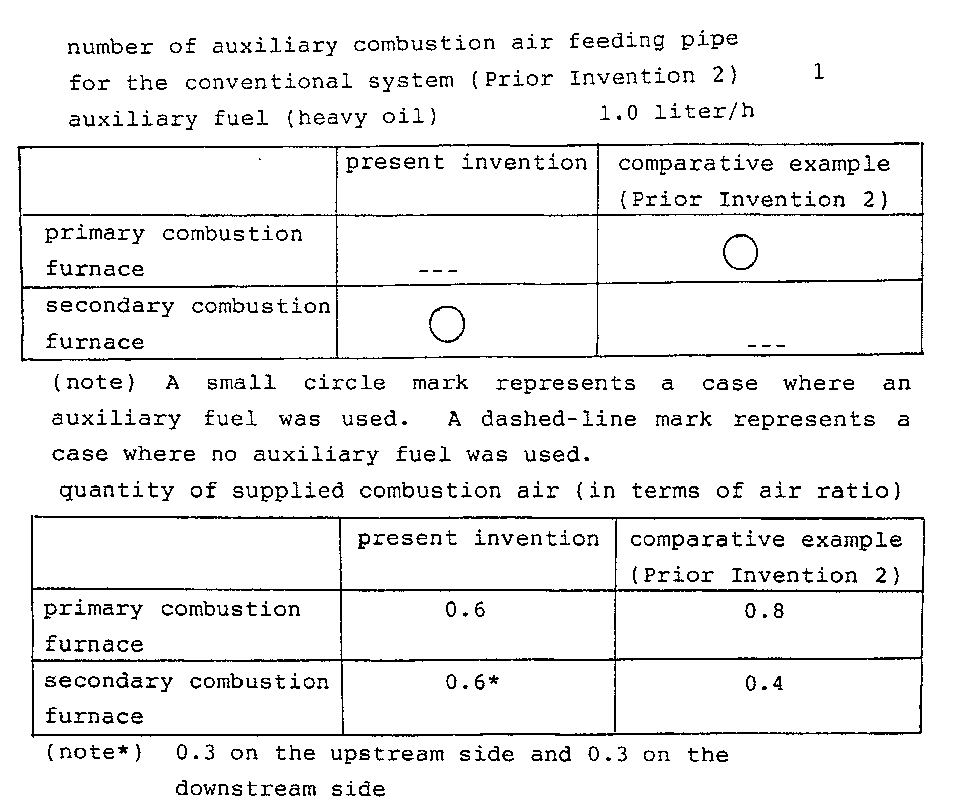
Table 2 shows results derived from operations under the above-noted conditions.
As will be apparent from the above two examples, the swirling flow type melting furnace (i.e., secondary combustion furnace) of the present invention makes it possible to continuously achieve combustion at a high operational efficiency under a high load for a long period of time. - Incidentally, Fig. 3 shows diagrams which represent a relationship between position and temperature in the combustion furnace in the upstream zone a, the intermediate zone b and the downstream zone c with respect to a state I where a temperature in the combustion furnace is controlled as well as a state II where a temperature in the combustion furnace is not controlled in connection with a position assumed by the baffle plate. It is obvious that the temperature is kept stable in the state I.
- As will be readily apparent from the above description, the system of the first invention offers the following advantageous effects.
- (1) Since waste material to be heat treated is heated up to a sufficiently high level of temperature in a region between the primary combustion furnace and the mixer by thermal energy included in the combustion air, there is few factor of degrading the high temperature atmosphere when the waste material is introduced into the primary combustion furnace.
- (2) Since high pressure/high temperature water is employed as a medium for extracting thermal energy from the furnace jacket, a castable refractory material for the second combustion furnace has a temperature which is sufficiently lower than a predetermined temperature at which the castable refractory material is not deteriorated, a frequency of exchanging the castable refractory material with new one can be reduced to one-fourth compared with the conventional system.
- (3) The baffle plate in the secondary combustion furnace is formed with an inverted U-shaped opening so as to allow a molten slag itself to provide a weir effect in the presence of the inverted U-shaped opening. Arrangement of the baffle plate assures that a staying time of waste gas in a swirling state in the secondary combustion furnace can be elongated to maintain fluidity of the molten slag.
- (4) The number of inlet ports for auxiliary combustion air to be introduced into the secondary combustion furnace can freely be selected while a quantity of combustion air to be consumed in the stable region in the secondary combustion furnace is totally controlled. Thus, an operation of the secondary combustion furnace can easily and automatically be performed corresponding to the current designing of the furnace.
- (5) There does not occur such a malfunction that the slag discharging passage is clogged with cooled/solidified slag.
- (6) Combustion air is fed to each combustion furnace in a swirling state while flowing along the inner wall surface of the combustion furnace in the tangential direction. Combustible components in waste material to be heat treated can completely be burnt with an ample quantity of oxygen fed into the combustion furnace.
- (7) Extracting of thermal energy from the combustion furnace, cooling of the cylindrical structure of the combustion furnace and feeding of thermal energy to the mixer can correctly be controlled using a water jacket and a heat exchanger. Additionally, flow rate, pressure and temperature of thermal mediums flowing through the water jacket and the heat exchanger can freely be adjusted without any particular necessity for maintenance.
- Next, a system for treating waste material in a molten state in accordance with an embodiment of a second invention will be described in detail hereinafter with reference to Figs. 15 to 18 and Figs. 21 to 24.
- As will be apparent from the following description, the purport of the present invention consists in that waste material in the form of dust floatable in waste gas is treated in a molten state.
- Referring to Fig. 15, waste material C to be heat treated is introduced into a drier 100 via a
feeder 111 so that it is dried while reducing its own weight. The dried waste material C is well mixed with combustion air A having a temperature of 400 to 600 °C in amixer 102 and thereafter the preheated waste material C is fed to amelting furnace 103. As required, themelting furnace 103 is additionally fed with fuel B so that incombustible material in the raw material C is converted into molten slag HH at a high temperature of 1350 to 1450 °C in a swirling flow, while combustible material in the waste material is gasified and discharged to the outside as waste gas D. The molten slag H deposited in a flowing state on the bottom of themelting furnace 103 is discharged as cooled slag EE to the outside of the system via aslag discharging unit 105 which is equipped with a slag cooling device (not shown). - On the other hand, gas in the
melting furnace 103 includes floatable dust FF in the form of fine droplets of molten slag and then it leaves themelting furnace 103 as waste gas D having a temperature in the range of 1000 to 1300 °C. The waste gas enters in a floatabledust removing unit 104 via awaste gas passage 117 while assuming a swirling flow state. Since the molten slag J in the waste gas D is introduced into thedust removing unit 104 in the above-described swirl flowing state, centrifugal force is exerted on the molten slag J so that the latter comes in close contact with the inner wall surface of theslag removing unit 104. Then, the molten slag J descends into themelting furnace 103 by its own dead weight against a counterflow of the waste gas D by way of the steps of agglomerating the molten slag J on the inner surface of thedust removing unit 104, displacing the molten slag J along the bottom surface of thedust removing unit 104, forming a flow of the molten slag J, displacing the slag flow on the inclined bottom surface of thedust removing unit 104 and displacing the slag flow into themelting furnace 103 via a wastegas inlet port 181. Consequently, the molten slag J is heated by the counterflow of the waste gas D to resume a fluidity, whereby the molten slag J is admixed with the molten slag HH deposited on the bottom of themelting furnace 103 and the slag mixture is discharged to the outside of the system via a wastematerial discharging unit 105. - After a number of floatable fine droplets of molten dust are removed from the waste gas KK in the
dust removing unit 104, the waste gas KK having a temperature of at least about 1000 °C is introduced into the heating side of anair preheater 107 in which its temperature is reduced to a level of about 200 °C or less so that thermal energy of the waste gas KK is utilized to preheat combustion air A. Then, the waste gas KK is delivered further to aboiler 109 in which the residual thermal energy of the waste gas KK is utilized. - After the waste gas leaves the
boiler 109, residual dust in the waste gas is removed in ascrubber 110 and it is finally discharged to the outside of the system by ablower 108. In case where it is required that dust in the waste gas is more completely removed in thescrubber 110, a dry type electric dust collector (not shown) is added to thescrubber 110. - The
air preheater 107 is utilized such that the combustion air A is preheated by thermal energy of the waste gas KK from a room temperature to a higher level in the range of 400 to 600 °C and the preheated air is finally utilized to heat the raw material which is dried in the drier 100. To prevent the wastematerial discharge passage 136 from being clogged with the molten slag KK until it reaches the wastematerial discharging unit 105, an auxiliary heating unit (not shown) for additionally heating the molten slag HH should preferably be arranged at the discharge portion (not shown) of themelting furnace 103 to satisfactorily maintain fluidity of the molten slag HH. - Next, the
dust removing unit 104 will be described in more details below with reference to Figs. 16 to 18. - As shown in the drawings, the waste gas D having floatable dust included therein reaches from the
melting furnace 103 via a waste gas passage 117 a wastegas inlet port 118 at the lower end of the cylindricaldust removing unit 104 which is installed in the horizontal direction with a certain uphill inclination angle of THETA, e.g., in the range of 2 to 40 degrees. A flow speed of the waste gas D to enter thedust removing unit 104 is controlled within the range of 15 to 60 m/sec, preferably higher than 30 m/sec. As is best seen in Fig. 17, the wastegas inlet port 181 is designed such that its upper side extends tangential to theinner wall 183 of thedust removing unit 104 so as to create a swirling flow in the interior of thedust removing unit 104 so as to allow the waste gas D to flow along the cylindrical inner wall of thedust removing unit 104. Further, the lower side of the wastegas inlet port 181 is designed to include thelowest surface 182 of the cylindrical structure of thedust removing unit 104, whereby the molten slag J of floatable dust can easily be displaced from thedust removing unit 104 down to themelting furnace 103. - The waste gas D having floatable dust included therein which has been introduced into the
dust removing unit 104 is converted into a swirling flow to stay in thedust removing unit 104 for a predetermined period of time. As required, the staying time can be adjusted by abaffle plate 141 on the downstream side of thedust removing unit 104. - Due to introduction of the waste gas D into the interior of the cylindrical structure of the
dust removing unit 104 in that way, centrifugal force is always exerted on the waste gas D staying within the atmosphere of thedust removing unit 141. Thus, molten slag droplets of floatable dust are collected on the cylindrical inner wall surface of thedust removing unit 104 under the effect of the aforementioned centrifugal force. In case where it is found that floating material includes non-molten floatable dust in the form of solid phase material or powder material, heating means, i.e., secondary combustionair feeding units dust removing unit 104 so as to liquidize all collected floating materials. - In this manner, the floatable dust collected on the inner wall surface of the cylindrical structure of the
dust removing unit 104 is displaced downwardly under the effect of centrifugal force and its own gravity force and increasingly agglomerated in the course of displacement until they are get together to become an agglomerated flow on the bottom surface of the cylindrical structure of thedust removing unit 104. As a result, a bottom flow of the molten slag J is produced along the bottom surface extending downward from the downstream side to the upstream side of thedust removing unit 104. - On the other hand, the waste gas KK from which floatable dust has been completely removed is delivered to a subsequent stage, i.e., a waste gas treating section via a waste
gas outlet port 119 on the downstream side of thedust removing unit 104. - According to the present invention, a jacket (not shown) is mounted round the outer wall surface of the
dust removing unit 104 and it is filled with fluid medium so as to prevent the cylindrical structure of thedust removing unit 104 from becoming excessively hot. The heated fluid medium is extracted from the jacket so as to allow it to be delivered to thermal energy utilizing means which is arranged at a separate location where the extracted thermal energy is utilized. - Here, description will be made below as to an embodiment of the present invention wherein no jacket is mounted round the outer wall surface of the
dust removing unit 104 to utilize thermal energy. - The
dust removing unit 104 was constructed such that it had a diameter of 0.4 m and a length of 3.3 mm as measured along the inner wall surface as a reference for measurement, the outside wall was made of mild steel plate, the inner wall was lined with a thermal insulating silica board as an intermediate layer, the inner most wall adapted to come in contact with waste gas was lined with heat resistance castable ceramic material and the cylindrical structure of thedust removing unit 104 was installed in an inclined state having an inclination angle THETA of 3 degrees. In case where it is found that the molten slag includes molten components each having a higher viscosity, the inclination angle THETA is properly set to a larger value than that of the foregoing embodiment. Incidentally, dried sludge derived from treatment of sewerage was used as raw material. - Results derived from operations performed with the system of the present invention are as shown in Table 3. Case I and Case II show results derived from operations performed with the system of the present invention. Case III shows results derived from operations performed with the same conventional system as that in Case I and Case II with the exception that units required for the system of the present invention were not employed. In the table, the floating material collection efficiency represents results derived measurements at the
waste gas passage 117 of themelting furnace 103.

- To facilitate understanding of the present invention, it will be helpful that essential components and mediums required for the system of the second invention are represented by reference numerals and reference characters in the following manner.
- In the drawings, reference numeral 106 designates an air preheater (heat absorbing side), reference numeral 112 designates a raw material inlet port, reference numeral 113 designates an outlet port of dried raw material, reference numeral 114 designates dried raw material conveyance passage, reference numeral 115 designates an inlet port of dried raw material, reference numeral 116 designates an outlet port of waste gas, reference numeral 118 designates an inlet port of waste gas, reference numeral 120 designates a dust-free waste gas passage, reference numeral 121 designates a dust-free waste gas inlet port, reference numeral 122 designates an outlet port of heat removed waste gas, reference numeral 123 designates a heat removed waste gas passage, reference numeral 124 designates a heat removed waste gas inlet port, reference numeral 125 designates a reheated energy conveyance passage (steam or hot water or gas), reference numeral 126 designates an outlet port of unused waste gas, reference numeral 127 designates a passage of unused waste gas, reference numeral 128 designates an inlet port of scrubber waste gas, reference numeral 129 designates an outlet of scrubber waste gas, reference numerals 131 and 132 designate a secondary combustion air feeding unit, respectively, reference numeral 133 designates an outlet port of heated primary air, reference numeral 134 designates a passage of heated primary air, reference numeral 135 designates a furnace outlet port of heated waste material, reference numeral 137 designates an inlet port of heated waste material, reference numeral 138 designates an outlet port of cooled waste material, reference numeral 139 designates a passage of cooled waste material, reference numeral 140 designates a cyclone, reference numeral 141 designates a baffle plate, reference numeral 142 designates a waste material storage, reference numeral 143 designates a lower outlet port of waste gas, reference numeral 150 designates an unused waste gas controlling passage, reference numeral 151 designates a primary air passage, reference numeral 152 designates an inlet port of primary air to be heated, reference numeral 160 designates an outlet port of floatable waste material, reference numeral 182 designates the lower side of an inlet port of waste gas, reference numeral 183 designates the upper side of an inlet port of waste gas, reference character RR designates a floatable dust, reference character GG designates a mixture of air and raw material to be heat treated and reference character LL designates a waste gas from the lower part of a cyclone.
- As will be apparent from the above description, the system in accordance with the second invention will offer the following advantageous effects.
- (1) Since a cost is required only for an operation in the waste material combustion furnace, the system can be designed at an inexpensive cost.
- (2) With the system of the present invention, floatable dust can easily be removed at a high efficiency in the atmosphere having a high temperature without any danger of causing a malfunction that relevant units are clogged with the waste material.
- (3) Heat generated by the dust removal can effectively be utilized for other technical systems rather than the system of the present invention.
- (4) A subsequent process or a subsequent step associated with the system of the present invention can be operated at a substantially improved efficiency. Thus, the whole system can be controlled and maintained at a reduced cost.
- While a system for treating waste material in a molten state in accordance with first and second inventions has been described above with respect to two typical embodiments, it should of course be understood that these systems should not be limited only to them but various changes and modifications may be made without departure from the scope of the both inventions as defined in the appended claims.
- Reference signs in the claims are intended for better understanding and shall not limit the scope.
Claims (17)
- A system for treating waste material in the form of sludge in a molten state wherein the sludge is first dried, the dried sludge is then treated at a high temperature in the atmosphere of a swirling flow to generate molten slag and the molten slag is cooled later, characterized in that after the dried sludge is well mixed with combustion air at a temperature in a primary combustion furnace (2) in the range of 400 to 600 °C, it is subjected to primary combustion at a temperature in the range of 1000 to 1200 °C while maintaining a swirling flow state, that a fluidized mixture derived from the primary combustion is fed into the atmosphere for secondary combustion in a secondary combustion furnace (3) at a temperature in the range of 1350 to 1450 °C while maintaining a swirling flow state, the secondary combustion being achieved by a plurality of temperature raising means (31, 32) arranged in a spaced relationship in a region extending from the upstream side to the downstream side of the secondary combustion furnace (3) to feed combustion air in a divided state, that after completely molten slag is displaced from the secondary combustion furnace (3) to a slag discharging section (4), the molten slag is cooled to be taken from the system as cooled slag, that on completion of the combustion, floatable dust is removed from waste gas and thermal energy included in the waste gas is transferred to fresh air by heat exchanging between the waste gas and the fresh air, and that the thus preheated air is distributed into the temperature raising means (22, 31. 32) to be used as combustion air for combustion in the primary combustion furnace (2) and the secondary combustion furnace (3).
- A system for treating waste material in the form of sludge in a molten state as claimed in claim 1, characterized in that a condensed water heating jacket (36) is mounted round the secondary combustion furnace (3) in which secondary combustion is achieved in a swirling flow state to heat condensed water having a temperature lower than about 90 °C coming from a drier (1) up to a temperature in the range of 180 to 190 °C and the resultant hot water is delivered to a boiler (9) together with the waste gas discharged from the second combustion furnace (3) to generate steam in the boiler (9), thermal energy included in the waste gas being transferred to fresh air by heat exchanging between the waste gas and the fresh air, pressure of the steam being reduced to a certain level so as to allow the pressure reduced steam to be used in the drier (1) as heating medium.
- A system for treating waste material in the form of sludge in a molten state as claimed in claim 1, characterized in that the preheated combustion air is substantially equally distributed into the primary combustion furnace (2) and the secondary combustion furnace (3).
- A system for treating waste material in the form of sludge in a molten state as claimed in claim 1 or 3, characterized in that the preheated air for combustion in the secondary combustion furnace (3) is equally distributed depending on the number of temperature raising means (31, 32) provided for combustion in the second combustion furnace (3).
- A system for treating waste material in the form of sludge in a molten state as claimed in claim 1 or 3, characterized in that the preheated combustion air is fed into the primary combustion furnace (2) and the secondary combustion furnace (3) in the tangential direction relative to the inner wall surface of each combustion furnace (2, 3) to generate a swirling flow of combustion gas.
- A system for treating waste material in the form of sludge in a molten state as claimed in claim 1, characterized in that the primary combustion furnace (2) is connected to the secondary combustion furnace (3) in a tangential relationship relative to the inner wall surface of the secondary combustion furnace (3) to generate a swirling flow of combustion gas in the interior of the secondary combustion furnace (3), the secondary combustion furnace (3) is mounted in a substantially horizontal direction such that the upstream side is raised up relative to the downstream side so as to allow the secondary combustion furnace (3) to assume an inclined attitude, a baffle plate (33) having an inverted U-shaped opening formed thereon is disposed in the vicinity of the downstream end of the secondary combustion furnace (3), and each temperature raising means (31, 32) is provided with a combustion air feeding port or an auxiliary burner in addition to said combustion air feeding port.
- A system for treating waste material in the form of sludge in a molten state as claimed in claim 6, characterized in that the secondary combustion furnace (3) is provided with a tongue-shaped concave slag discharging passage (34) at the downstream end thereof, the slag discharging passage (34) being protruded from the bottom of the secondary combustion furnace (3) toward the slag discharging section (4).
- A system for treating waste material in a molten state wherein the waste material including combustible material and incombustible material is burnt at a high temperature to produce molten slag and the resultant molten slag is cooled to receive final treating, characterized in that waste gas discharged from a combustion furnace (103) is introduced into a floatable dust removing unit (104) in which floatable dust in the waste gas is collected and agglomerated to produce molten slag in the atmosphere of a swirling flow having a high temperature which is determined at least within a range of allowing incombustible material in the waste material to be molten in the swirling flow, and that the resultant molten slag flows down by its own dead weight to the discharging side of thed combustion furnace (103) against a counterflow of the upwardly flowing waste gas.
- A system for treating waste material in a molten state as claimed in claim 8, characterized in that collecting and agglomerating of floatable dust in the waste gas coming from the combustion furnace (103) are achieved by introducing the waste gas into the dust removing unit (104) in the atmosphere of a swirling flow in the tangential direction relative to the inner wall surface of the dust removing unit (104).
- A system for treating waste material in a molten state wherein the waste material including combustible material and incombustible material is burnt at a high temperature to produce molten combustion ash or molten slag and said molten combustion ash or the molten slag is cooled to receive final treating, characterized in that waste gas discharged from a combustion furnace (103) or a melting furnace (103) is introduced into a floatable dust removing unit (104) in which floatable dust in the waste gas is treated at a high temperature in the atmosphere of a swirling flow so as to allow the incombustible material to be molten, that tha floatable dust which has not been molten is collected and agglomerated to produce a flow of molten slag, and that the resultant molten slag flows down by its own dead weight to the discharging side of the combustion furnace (103) or the melting furnace (103) against a counterflow of the upward flowing waste gas.
- A system for treating waste material in a molten state as claimed in claim 10, characterized in that treatment of the waste gas from the combustion furnace (103) or the melting furnace (103) in the atmosphere of a swirling flow at a high temperature is achieved by introducing the waste gas into the atmosphere of a swirling flow in the tangential direction relative to the inner wall surface of the dust removing unit (104).
- A system for treating waste material in a molten state as claimed in claim 10, characterized in that treatment of the waste gas from the combustion furnace (103) or the melting furnace (103) in the atmosphere of a swirling flow at a high temperature is achieved by additionally introducing auxiliary heating gas comprising combustion air and auxiliary fuel through temperature raising means (131, 132) in the tangential direction relative to the inner wall surface of the dust removing unit (104), thed temperature raising means (131, 132) being disposed at properly determined locations in the atmosphere of the swirling flow in the dust removing unit (104).
- A system for treating waste material in a molten state as claimed in claim 10, characterized in that the dust removing unit (104) includes a waste gas inlet port (118) on the upstream side of the cylindrical structure and a dust-free waste gas outlet port (119) on the downstream side of the cylindrical structure thereof, the inlet port (118) extending into the dust removing unit (104) in the substantially tangential direction relative to the inner wall surface of the cylindrical structure thereof, and that the dust removing unit (104) is mounted in the substantially horizontal direction such that the upstream side is located below the downstream side so as to allow the dust removing unit (104) to assume an inclined attitude.
- A system for treating waste material in a molten state as claimed in claim 10, characterized in that the dust removing unit (104) includes a waste gas inlet port (118) on the upstream side of the cylindrical structure and a dust-free waste gas outlet port (119) on the downstream side of the cylindrical structure thereof, the inlet port (118) extending into the dust removing unit (104) in the substantially tangential direction relative to the inner wall surface of the cylindrical structure thereof, that a properly determined number of auxiliary heating gas feeding means (131. 132) are arranged in an intermediate zone between the upstream side and the downstream side of the dust removing unit (104), and that the dust removing unit (104) is mounted in the substantially horizontal direction such that the upstream side is located below the downstream side so as to allow the dust removing unit (104) to assume an inclined attitude.
- A system for treating waste material in a molten state as claimed in claim 13 or 14, characterized in that the cylindrical structure of the dust removing unit (104) is formed with a waste gas inlet port (118) the upper part of which (183) extends in the substantially tangential direction relative to the inner wall surface of the cylindrical structure, the waste gas inlet port being opened while assuming an elongated circle as seen from the above, the lower part (182) of the waste gas inlet port (118) being located to include the lowest part (182) of the inner wall surface of the cylindrical structure of the dust removing unit (104).
- A system for treating waste material in a molten state as claimed in claim 13 or 14, characterized in that the dust removing unit (104) is provided with a baffle plate (141) in the vicinity of the downstream end of the cylindrical structure thereof so that the dust-free waste gas flows through an opening which is formed on said baffle plate (141).
- A system for treating waste material in a molten state as claimed in claim 13 or 14, characterized in that a jacket is mounted round the cylindrical structure of the dust removing unit (104) so that a thermal energy carrying medium is introduced into and extracted from the jacket to receive thermal energy from the interior of the dust removing unit (104).
Priority Applications (6)
| Application Number | Priority Date | Filing Date | Title |
|---|---|---|---|
| US07/460,579 US5020455A (en) | 1990-01-11 | 1990-01-03 | System for treating waste material in a molten state |
| ES90100518T ES2050279T3 (en) | 1990-01-11 | 1990-01-11 | A SYSTEM FOR THE TREATMENT OF RESIDUAL MATERIAL IN A CAST STATE. |
| DE90100518T DE69002605T2 (en) | 1990-01-11 | 1990-01-11 | System for the treatment of waste in the molten state. |
| AT90100518T ATE92603T1 (en) | 1990-01-11 | 1990-01-11 | SYSTEM FOR TREATMENT OF WASTE IN MOLTEN STATE. |
| EP90100518A EP0436759B1 (en) | 1990-01-11 | 1990-01-11 | A system for treating waste material in a molten state |
| US07/560,110 US5081937A (en) | 1990-01-11 | 1990-07-31 | System for treating waste material in a molten state |
Applications Claiming Priority (1)
| Application Number | Priority Date | Filing Date | Title |
|---|---|---|---|
| EP90100518A EP0436759B1 (en) | 1990-01-11 | 1990-01-11 | A system for treating waste material in a molten state |
Publications (2)
| Publication Number | Publication Date |
|---|---|
| EP0436759A1 true EP0436759A1 (en) | 1991-07-17 |
| EP0436759B1 EP0436759B1 (en) | 1993-08-04 |
Family
ID=8203478
Family Applications (1)
| Application Number | Title | Priority Date | Filing Date |
|---|---|---|---|
| EP90100518A Expired - Lifetime EP0436759B1 (en) | 1990-01-11 | 1990-01-11 | A system for treating waste material in a molten state |
Country Status (5)
| Country | Link |
|---|---|
| US (2) | US5020455A (en) |
| EP (1) | EP0436759B1 (en) |
| AT (1) | ATE92603T1 (en) |
| DE (1) | DE69002605T2 (en) |
| ES (1) | ES2050279T3 (en) |
Cited By (6)
| Publication number | Priority date | Publication date | Assignee | Title |
|---|---|---|---|---|
| EP0570949A1 (en) * | 1992-05-20 | 1993-11-24 | Ebara Corporation | Dried sludge melting furnace |
| EP0726231A1 (en) * | 1995-02-08 | 1996-08-14 | Klöckner-Humboldt-Deutz Aktiengesellschaft | Process and apparatus for the thermic treatment of solid materials |
| EP0777838A1 (en) * | 1994-08-26 | 1997-06-11 | Minergy Corp. | Converting paper mill sludge or the like |
| FR2795161A1 (en) * | 1999-06-18 | 2000-12-22 | Francis Morra | Generator of heat and thermal energy, comprises combustion chamber into which particles of waste products are injected with hot combustion supporting gas |
| CN102798130A (en) * | 2012-09-07 | 2012-11-28 | 中国东方电气集团有限公司 | System for relieving scorification of convection heated surface of boiler |
| CN103591596A (en) * | 2013-10-29 | 2014-02-19 | 七台河宝泰隆煤化工股份有限公司 | Dust removing system of boiler slag tapping equipment |
Families Citing this family (17)
| Publication number | Priority date | Publication date | Assignee | Title |
|---|---|---|---|---|
| JPH0826974B2 (en) * | 1993-04-26 | 1996-03-21 | 高茂産業株式会社 | Incinerator |
| US5476990A (en) * | 1993-06-29 | 1995-12-19 | Aluminum Company Of America | Waste management facility |
| US5473998A (en) * | 1994-04-25 | 1995-12-12 | Holnam, Inc. | Cement kiln having tire injection system |
| US8083787B2 (en) | 2005-07-18 | 2011-12-27 | Tearscience, Inc. | Method and apparatus for treating meibomian gland dysfunction |
| US7981145B2 (en) | 2005-07-18 | 2011-07-19 | Tearscience Inc. | Treatment of meibomian glands |
| US20090043365A1 (en) | 2005-07-18 | 2009-02-12 | Kolis Scientific, Inc. | Methods, apparatuses, and systems for reducing intraocular pressure as a means of preventing or treating open-angle glaucoma |
| US20080114423A1 (en) | 2006-05-15 | 2008-05-15 | Grenon Stephen M | Apparatus for inner eyelid treatment of meibomian gland dysfunction |
| US20070060988A1 (en) | 2005-07-18 | 2007-03-15 | Grenon Stephen M | Melting meibomian gland obstructions |
| US7520743B1 (en) | 2007-01-02 | 2009-04-21 | Chemical Applications And Engineering, Inc. | Method and apparatus to reduce a venting of raw natural gas emissions |
| CN101980973B (en) * | 2008-03-25 | 2016-05-11 | 旭硝子欧洲玻璃公司 | Glass melting furnace |
| US9221703B2 (en) * | 2008-03-25 | 2015-12-29 | Agc Glass Europe | Glass melting furnace |
| CN102425797A (en) * | 2011-11-08 | 2012-04-25 | 东南大学 | Combined cyclone boiler combustion device and device for flying ash fusion |
| CN102620299A (en) * | 2012-04-13 | 2012-08-01 | 南京信业能源科技有限公司 | Cyclone melting device and method for fly ash preheating |
| CN104534456A (en) * | 2014-12-24 | 2015-04-22 | 山西蓝天环保设备有限公司 | Low-ash-fusion coal fired boiler adopting horizontal extended furnace |
| CN107504492B (en) * | 2017-09-25 | 2023-06-27 | 马钢集团设计研究院有限责任公司 | Industrial sludge, waste emulsion residue and metallurgical ash combined treatment system and power generation process thereof |
| CN110068020B (en) * | 2019-05-22 | 2020-07-28 | 中国神华能源股份有限公司 | Slag storehouse dust pelletizing system |
| CN114307033B (en) * | 2021-12-21 | 2022-12-02 | 山东天力能源股份有限公司 | Waste salt drying and pyrolysis system and method |
Citations (8)
| Publication number | Priority date | Publication date | Assignee | Title |
|---|---|---|---|---|
| DE1087742B (en) * | 1952-04-30 | 1960-08-25 | Stadt Duesseldorf Stadtwerke V | Cyclone firing |
| FR1296150A (en) * | 1961-06-13 | 1962-06-15 | Steam & Power Dev Company Ltd | Process for the separation of solid and liquid particles in suspension from fluid media |
| CH470207A (en) * | 1966-04-26 | 1969-03-31 | Babcock & Wilcox France | High temperature gas purification device |
| US3457883A (en) * | 1967-05-08 | 1969-07-29 | Borge Richard Ankersen | Incinerators and methods of incineration |
| US3543700A (en) * | 1969-07-07 | 1970-12-01 | Environmental Control Products | Air purifying incinerator apparatus |
| US4015546A (en) * | 1975-10-09 | 1977-04-05 | Paules Eugene H | Apparatus and method for converting refuse to useful energy |
| DE2654428A1 (en) * | 1976-12-01 | 1978-06-08 | Kurt Gaidies | Refuse incinerator system with high heat output - has vertical furnace and adjacent after burner and tangential air supply nozzles |
| FR2518525A1 (en) * | 1981-12-21 | 1983-06-24 | Nippon Furnace Kogyo Kk | DEVICE FOR RECOVERING PRODUCTS AND ENERGY FROM SLUDGE |
Family Cites Families (17)
| Publication number | Priority date | Publication date | Assignee | Title |
|---|---|---|---|---|
| US2881720A (en) * | 1950-06-21 | 1959-04-14 | Babcock & Wilcox Co | Cyclone furnaces |
| US2800091A (en) * | 1952-02-06 | 1957-07-23 | Babcock & Wilcox Co | Cyclone furnace |
| US2891493A (en) * | 1954-09-07 | 1959-06-23 | Babcock & Wilcox Co | Method of and apparatus for burning particle-form fuel |
| JPS5822881A (en) * | 1981-08-03 | 1983-02-10 | 川崎重工業株式会社 | Rotary kiln and direct reduction method of metallic oxide using said kiln |
| DE3212009A1 (en) * | 1982-03-31 | 1983-10-06 | Krupp Polysius Ag | METHOD AND DEVICE FOR THE HEAT TREATMENT OF FINE GRAIN GOODS |
| US4546711A (en) * | 1983-10-24 | 1985-10-15 | Marblehead Lime Company | Apparatus and method for incinerating waste material with a converted preheater-type lime kiln |
| US4599955A (en) * | 1984-10-24 | 1986-07-15 | Amax Inc. | Coal slagging burner for producing clean low-sulfur fuel gas |
| US4685404A (en) * | 1984-11-13 | 1987-08-11 | Trw Inc. | Slagging combustion system |
| JPH0650172B2 (en) * | 1985-03-19 | 1994-06-29 | 月島機械株式会社 | Combustion method for solid substances containing incombustibles in swirl flow melting equipment |
| DE3520058A1 (en) * | 1985-06-04 | 1986-12-04 | O & K Orenstein & Koppel Ag, 1000 Berlin | METHOD FOR THE HEAT TREATMENT OF FINE GRAIN GOODS |
| US4794871A (en) * | 1985-08-19 | 1989-01-03 | Environment Protection Engineers, Inc. | Method and installation for the treatment of material contaminated with toxic organic compounds |
| JPS6370015A (en) * | 1986-09-09 | 1988-03-30 | Daido Steel Co Ltd | Combustion-melting furnace of cyclone type for sewer sewage |
| JPH0833190B2 (en) * | 1987-01-12 | 1996-03-29 | 月島機械株式会社 | Swirl melting furnace |
| US4734166A (en) * | 1987-02-05 | 1988-03-29 | Angelo Ii James F | Furnace for the selective incineration or carbonization of waste materials |
| DE3725512A1 (en) * | 1987-07-29 | 1989-02-09 | Kettenbauer Gmbh & Co Verfahre | FLOATING GAS REACTOR |
| US4751887A (en) * | 1987-09-15 | 1988-06-21 | Environmental Pyrogenics Services, Inc. | Treatment of oil field wastes |
| US4834648A (en) * | 1987-09-17 | 1989-05-30 | Angelo Ii James F | Rotary calcining kiln |
-
1990
- 1990-01-03 US US07/460,579 patent/US5020455A/en not_active Expired - Lifetime
- 1990-01-11 DE DE90100518T patent/DE69002605T2/en not_active Expired - Lifetime
- 1990-01-11 ES ES90100518T patent/ES2050279T3/en not_active Expired - Lifetime
- 1990-01-11 EP EP90100518A patent/EP0436759B1/en not_active Expired - Lifetime
- 1990-01-11 AT AT90100518T patent/ATE92603T1/en not_active IP Right Cessation
- 1990-07-31 US US07/560,110 patent/US5081937A/en not_active Expired - Fee Related
Patent Citations (8)
| Publication number | Priority date | Publication date | Assignee | Title |
|---|---|---|---|---|
| DE1087742B (en) * | 1952-04-30 | 1960-08-25 | Stadt Duesseldorf Stadtwerke V | Cyclone firing |
| FR1296150A (en) * | 1961-06-13 | 1962-06-15 | Steam & Power Dev Company Ltd | Process for the separation of solid and liquid particles in suspension from fluid media |
| CH470207A (en) * | 1966-04-26 | 1969-03-31 | Babcock & Wilcox France | High temperature gas purification device |
| US3457883A (en) * | 1967-05-08 | 1969-07-29 | Borge Richard Ankersen | Incinerators and methods of incineration |
| US3543700A (en) * | 1969-07-07 | 1970-12-01 | Environmental Control Products | Air purifying incinerator apparatus |
| US4015546A (en) * | 1975-10-09 | 1977-04-05 | Paules Eugene H | Apparatus and method for converting refuse to useful energy |
| DE2654428A1 (en) * | 1976-12-01 | 1978-06-08 | Kurt Gaidies | Refuse incinerator system with high heat output - has vertical furnace and adjacent after burner and tangential air supply nozzles |
| FR2518525A1 (en) * | 1981-12-21 | 1983-06-24 | Nippon Furnace Kogyo Kk | DEVICE FOR RECOVERING PRODUCTS AND ENERGY FROM SLUDGE |
Non-Patent Citations (4)
| Title |
|---|
| PATENT ABSTRACTS OF JAPAN, vol. 10, no. 238 (M-508)[2294], 16th August 1986; & JP,A,61 070 314 (NGK INSULATORS LTD) 11-04-1986, abstract. * |
| PATENT ABSTRACTS OF JAPAN, vol. 11, no. 50 (M-562)[2497], 17th February 1987, page 97 M 562; & JP,A,61 213 408 (TSUKISHIMA KIKAI CO., LTD) 22-09-1986, abstarct. * |
| PATENT ABSTRACTS OF JAPAN, vol. 14, no. 186 (M-962)[4129], 16th April 1990; & JP,A,2 033 511 (TSUKISHIMA KIKAI) 02-02-1990. * |
| PATENT ABSTRACTS OF JAPAN, vol. 14, no. 206 (M-967)[4149], 26th April 1990; & JP,A,2 044 113 (TSUKISHIMA KIKAI) 14-02-1990. * |
Cited By (9)
| Publication number | Priority date | Publication date | Assignee | Title |
|---|---|---|---|---|
| EP0570949A1 (en) * | 1992-05-20 | 1993-11-24 | Ebara Corporation | Dried sludge melting furnace |
| US5357879A (en) * | 1992-05-20 | 1994-10-25 | Ebara-Infilco Co., Ltd. | Dried sludge melting furnace |
| EP0683359A3 (en) * | 1992-05-20 | 1996-05-01 | Ebara Infilco | Dried sludge melting furnace. |
| EP0777838A1 (en) * | 1994-08-26 | 1997-06-11 | Minergy Corp. | Converting paper mill sludge or the like |
| EP0777838A4 (en) * | 1994-08-26 | 1998-04-22 | Minergy Corp | Converting paper mill sludge or the like |
| EP0726231A1 (en) * | 1995-02-08 | 1996-08-14 | Klöckner-Humboldt-Deutz Aktiengesellschaft | Process and apparatus for the thermic treatment of solid materials |
| FR2795161A1 (en) * | 1999-06-18 | 2000-12-22 | Francis Morra | Generator of heat and thermal energy, comprises combustion chamber into which particles of waste products are injected with hot combustion supporting gas |
| CN102798130A (en) * | 2012-09-07 | 2012-11-28 | 中国东方电气集团有限公司 | System for relieving scorification of convection heated surface of boiler |
| CN103591596A (en) * | 2013-10-29 | 2014-02-19 | 七台河宝泰隆煤化工股份有限公司 | Dust removing system of boiler slag tapping equipment |
Also Published As
| Publication number | Publication date |
|---|---|
| ES2050279T3 (en) | 1994-05-16 |
| DE69002605T2 (en) | 1993-12-16 |
| US5081937A (en) | 1992-01-21 |
| ATE92603T1 (en) | 1993-08-15 |
| US5020455A (en) | 1991-06-04 |
| EP0436759B1 (en) | 1993-08-04 |
| DE69002605D1 (en) | 1993-09-09 |
Similar Documents
| Publication | Publication Date | Title |
|---|---|---|
| EP0436759B1 (en) | A system for treating waste material in a molten state | |
| US4253409A (en) | Coal burning arrangement | |
| KR100325282B1 (en) | Fuel and sorbent feed for circulating fluidized bed steam generator | |
| EP0005965B1 (en) | Method and boiler for the disposal of waste products by combustion | |
| US4583468A (en) | Method and apparatus for combustion of diverse materials and heat utilization | |
| JPS59112113A (en) | Waste incinerator | |
| CA2013010C (en) | Sludge incineration in single-stage combustor with gas scrubbing followed by afterburning and heat recovery | |
| JPH0133722B2 (en) | ||
| JPS63274642A (en) | Cement manufacturing apparatus | |
| US4724777A (en) | Apparatus for combustion of diverse materials and heat utilization | |
| US4969404A (en) | Ash classifier-cooler-combustor | |
| EP0687855B1 (en) | Circulating fluidized bed reactor for low grade fuels | |
| US3970011A (en) | Combustion with fluidizable bed | |
| EP0431163A1 (en) | Composite circulation fluidized bed boiler | |
| DK166694B1 (en) | PROCEDURE FOR MANAGING A FLUID BED BOILER AND FLUID BED BOILER FOR USE IN EXERCISING THE PROCEDURE | |
| EP0577759B1 (en) | Concurrent-flow multiple hearth furnace for the incineration of sewage sludge filter-cake | |
| JPS62236891A (en) | Method and apparatus for gasification in coal gasification oven | |
| US4301747A (en) | High temperature furnace with improved slag tap | |
| JPH054565B2 (en) | ||
| JP2722079B2 (en) | Method and apparatus for removing suspended dust in high-temperature atmosphere | |
| US3888632A (en) | Combustion chamber | |
| JP3886311B2 (en) | Burner ash melting equipment | |
| JP2901752B2 (en) | Fluidized bed combustion device | |
| JPS62196522A (en) | Heat recovery method from fluidized bed and its equipment | |
| US3666248A (en) | Afterburners for cupola furnaces |
Legal Events
| Date | Code | Title | Description |
|---|---|---|---|
| PUAI | Public reference made under article 153(3) epc to a published international application that has entered the european phase |
Free format text: ORIGINAL CODE: 0009012 |
|
| 17P | Request for examination filed |
Effective date: 19900111 |
|
| AK | Designated contracting states |
Kind code of ref document: A1 Designated state(s): AT BE CH DE DK ES FR GB GR IT LI LU NL SE |
|
| 17Q | First examination report despatched |
Effective date: 19920206 |
|
| RAP1 | Party data changed (applicant data changed or rights of an application transferred) |
Owner name: CHIBA CITY Owner name: TSUKISHIMA KIKAI KABUSHIKI KAISHA |
|
| GRAA | (expected) grant |
Free format text: ORIGINAL CODE: 0009210 |
|
| AK | Designated contracting states |
Kind code of ref document: B1 Designated state(s): AT BE CH DE DK ES FR GB GR IT LI LU NL SE |
|
| PG25 | Lapsed in a contracting state [announced via postgrant information from national office to epo] |
Ref country code: DK Effective date: 19930804 Ref country code: GR Free format text: LAPSE BECAUSE OF FAILURE TO SUBMIT A TRANSLATION OF THE DESCRIPTION OR TO PAY THE FEE WITHIN THE PRESCRIBED TIME-LIMIT Effective date: 19930804 |
|
| REF | Corresponds to: |
Ref document number: 92603 Country of ref document: AT Date of ref document: 19930815 Kind code of ref document: T |
|
| REF | Corresponds to: |
Ref document number: 69002605 Country of ref document: DE Date of ref document: 19930909 |
|
| ITF | It: translation for a ep patent filed |
Owner name: ST. DR. CAVATTONI ING. A. RAIMONDI |
|
| ET | Fr: translation filed | ||
| EPTA | Lu: last paid annual fee | ||
| REG | Reference to a national code |
Ref country code: ES Ref legal event code: FG2A Ref document number: 2050279 Country of ref document: ES Kind code of ref document: T3 |
|
| PLBE | No opposition filed within time limit |
Free format text: ORIGINAL CODE: 0009261 |
|
| STAA | Information on the status of an ep patent application or granted ep patent |
Free format text: STATUS: NO OPPOSITION FILED WITHIN TIME LIMIT |
|
| 26N | No opposition filed | ||
| EAL | Se: european patent in force in sweden |
Ref document number: 90100518.1 |
|
| ITTA | It: last paid annual fee | ||
| PGFP | Annual fee paid to national office [announced via postgrant information from national office to epo] |
Ref country code: SE Payment date: 19990210 Year of fee payment: 10 |
|
| PGFP | Annual fee paid to national office [announced via postgrant information from national office to epo] |
Ref country code: CH Payment date: 19990225 Year of fee payment: 10 |
|
| PGFP | Annual fee paid to national office [announced via postgrant information from national office to epo] |
Ref country code: LU Payment date: 19990331 Year of fee payment: 10 |
|
| PG25 | Lapsed in a contracting state [announced via postgrant information from national office to epo] |
Ref country code: LU Free format text: LAPSE BECAUSE OF NON-PAYMENT OF DUE FEES Effective date: 20000111 |
|
| PG25 | Lapsed in a contracting state [announced via postgrant information from national office to epo] |
Ref country code: SE Free format text: LAPSE BECAUSE OF NON-PAYMENT OF DUE FEES Effective date: 20000112 |
|
| PG25 | Lapsed in a contracting state [announced via postgrant information from national office to epo] |
Ref country code: CH Free format text: LAPSE BECAUSE OF NON-PAYMENT OF DUE FEES Effective date: 20000131 Ref country code: LI Free format text: LAPSE BECAUSE OF NON-PAYMENT OF DUE FEES Effective date: 20000131 |
|
| EUG | Se: european patent has lapsed |
Ref document number: 90100518.1 |
|
| REG | Reference to a national code |
Ref country code: CH Ref legal event code: PL |
|
| REG | Reference to a national code |
Ref country code: GB Ref legal event code: IF02 |
|
| PGFP | Annual fee paid to national office [announced via postgrant information from national office to epo] |
Ref country code: GB Payment date: 20040114 Year of fee payment: 15 |
|
| PGFP | Annual fee paid to national office [announced via postgrant information from national office to epo] |
Ref country code: FR Payment date: 20040126 Year of fee payment: 15 |
|
| PGFP | Annual fee paid to national office [announced via postgrant information from national office to epo] |
Ref country code: AT Payment date: 20040127 Year of fee payment: 15 |
|
| PGFP | Annual fee paid to national office [announced via postgrant information from national office to epo] |
Ref country code: BE Payment date: 20040128 Year of fee payment: 15 |
|
| PGFP | Annual fee paid to national office [announced via postgrant information from national office to epo] |
Ref country code: ES Payment date: 20040130 Year of fee payment: 15 |
|
| PG25 | Lapsed in a contracting state [announced via postgrant information from national office to epo] |
Ref country code: IT Free format text: LAPSE BECAUSE OF NON-PAYMENT OF DUE FEES;WARNING: LAPSES OF ITALIAN PATENTS WITH EFFECTIVE DATE BEFORE 2007 MAY HAVE OCCURRED AT ANY TIME BEFORE 2007. THE CORRECT EFFECTIVE DATE MAY BE DIFFERENT FROM THE ONE RECORDED. Effective date: 20050111 Ref country code: AT Free format text: LAPSE BECAUSE OF NON-PAYMENT OF DUE FEES Effective date: 20050111 Ref country code: GB Free format text: LAPSE BECAUSE OF NON-PAYMENT OF DUE FEES Effective date: 20050111 |
|
| PG25 | Lapsed in a contracting state [announced via postgrant information from national office to epo] |
Ref country code: ES Free format text: LAPSE BECAUSE OF NON-PAYMENT OF DUE FEES Effective date: 20050112 |
|
| PG25 | Lapsed in a contracting state [announced via postgrant information from national office to epo] |
Ref country code: BE Free format text: LAPSE BECAUSE OF NON-PAYMENT OF DUE FEES Effective date: 20050131 |
|
| BERE | Be: lapsed |
Owner name: *TSUKISHIMA KIKAI K.K. Effective date: 20050131 Owner name: *CHIBA CITY Effective date: 20050131 |
|
| GBPC | Gb: european patent ceased through non-payment of renewal fee |
Effective date: 20050111 |
|
| PG25 | Lapsed in a contracting state [announced via postgrant information from national office to epo] |
Ref country code: FR Free format text: LAPSE BECAUSE OF NON-PAYMENT OF DUE FEES Effective date: 20050930 |
|
| REG | Reference to a national code |
Ref country code: FR Ref legal event code: ST |
|
| REG | Reference to a national code |
Ref country code: ES Ref legal event code: FD2A Effective date: 20050112 |
|
| BERE | Be: lapsed |
Owner name: *TSUKISHIMA KIKAI K.K. Effective date: 20050131 Owner name: *CHIBA CITY Effective date: 20050131 |
|
| PGFP | Annual fee paid to national office [announced via postgrant information from national office to epo] |
Ref country code: DE Payment date: 20090128 Year of fee payment: 20 Ref country code: NL Payment date: 20090129 Year of fee payment: 20 |
|
| NLV7 | Nl: ceased due to reaching the maximum lifetime of a patent |
Effective date: 20100111 |
|
| PG25 | Lapsed in a contracting state [announced via postgrant information from national office to epo] |
Ref country code: NL Free format text: LAPSE BECAUSE OF EXPIRATION OF PROTECTION Effective date: 20100111 |
|
| PG25 | Lapsed in a contracting state [announced via postgrant information from national office to epo] |
Ref country code: DE Free format text: LAPSE BECAUSE OF EXPIRATION OF PROTECTION Effective date: 20100111 |