EP0436742A1 - Reluctance motor - Google Patents
Reluctance motor Download PDFInfo
- Publication number
- EP0436742A1 EP0436742A1 EP19900911711 EP90911711A EP0436742A1 EP 0436742 A1 EP0436742 A1 EP 0436742A1 EP 19900911711 EP19900911711 EP 19900911711 EP 90911711 A EP90911711 A EP 90911711A EP 0436742 A1 EP0436742 A1 EP 0436742A1
- Authority
- EP
- European Patent Office
- Prior art keywords
- armature
- position detecting
- armature coils
- torque
- energized
- Prior art date
- Legal status (The legal status is an assumption and is not a legal conclusion. Google has not performed a legal analysis and makes no representation as to the accuracy of the status listed.)
- Granted
Links
- 239000004065 semiconductor Substances 0.000 claims description 18
- 239000003990 capacitor Substances 0.000 abstract description 20
- 230000007423 decrease Effects 0.000 abstract description 11
- 230000000694 effects Effects 0.000 description 15
- 230000009471 action Effects 0.000 description 12
- 238000011161 development Methods 0.000 description 5
- 230000018109 developmental process Effects 0.000 description 5
- 230000004907 flux Effects 0.000 description 5
- XEEYBQQBJWHFJM-UHFFFAOYSA-N Iron Chemical compound [Fe] XEEYBQQBJWHFJM-UHFFFAOYSA-N 0.000 description 4
- 230000009467 reduction Effects 0.000 description 4
- 229910000976 Electrical steel Inorganic materials 0.000 description 3
- 239000002131 composite material Substances 0.000 description 3
- 238000010030 laminating Methods 0.000 description 3
- 238000006243 chemical reaction Methods 0.000 description 2
- 238000010276 construction Methods 0.000 description 2
- 230000003247 decreasing effect Effects 0.000 description 2
- 230000007547 defect Effects 0.000 description 2
- 230000001934 delay Effects 0.000 description 2
- 230000005284 excitation Effects 0.000 description 2
- 238000009499 grossing Methods 0.000 description 2
- 229910052742 iron Inorganic materials 0.000 description 2
- 230000005415 magnetization Effects 0.000 description 2
- 230000000630 rising effect Effects 0.000 description 2
- RYGMFSIKBFXOCR-UHFFFAOYSA-N Copper Chemical compound [Cu] RYGMFSIKBFXOCR-UHFFFAOYSA-N 0.000 description 1
- 239000004411 aluminium Substances 0.000 description 1
- XAGFODPZIPBFFR-UHFFFAOYSA-N aluminium Chemical compound [Al] XAGFODPZIPBFFR-UHFFFAOYSA-N 0.000 description 1
- 229910052782 aluminium Inorganic materials 0.000 description 1
- 230000015556 catabolic process Effects 0.000 description 1
- 230000008859 change Effects 0.000 description 1
- 239000010949 copper Substances 0.000 description 1
- 229910052802 copper Inorganic materials 0.000 description 1
- 238000006731 degradation reaction Methods 0.000 description 1
- 230000003111 delayed effect Effects 0.000 description 1
- 238000001514 detection method Methods 0.000 description 1
- 230000014509 gene expression Effects 0.000 description 1
- 238000005259 measurement Methods 0.000 description 1
- 230000010355 oscillation Effects 0.000 description 1
- 230000002035 prolonged effect Effects 0.000 description 1
- 230000004044 response Effects 0.000 description 1
Images


Classifications
-
- H—ELECTRICITY
- H02—GENERATION; CONVERSION OR DISTRIBUTION OF ELECTRIC POWER
- H02P—CONTROL OR REGULATION OF ELECTRIC MOTORS, ELECTRIC GENERATORS OR DYNAMO-ELECTRIC CONVERTERS; CONTROLLING TRANSFORMERS, REACTORS OR CHOKE COILS
- H02P25/00—Arrangements or methods for the control of AC motors characterised by the kind of AC motor or by structural details
- H02P25/02—Arrangements or methods for the control of AC motors characterised by the kind of AC motor or by structural details characterised by the kind of motor
- H02P25/08—Reluctance motors
- H02P25/086—Commutation
- H02P25/089—Sensorless control
Definitions
- This invention is related to a reluctance-type electric motor which is used for the drive source of industrial equipment as a highly efficient D.C. motor of a large output torque and less torque ripple, and which is particularly effective when used as a servo motor.
- the number of the magnetic poles of the armature becomes large and the air-gap of the magnetic path thereof is small, so that the stored magnetic energy is large, whereby the above-mentioned inconvenience is accelerated.
- a reluctance-type motor the ripple torque of which has been removed comprising: a position detecting unit including position detecting elements for detecting positions of salient poles by which a first, second, third and fourth single-phase position detecting signals are obtained in which there are disposed continuous position detecting signals having a width of 90 degrees in electrical angle that are not superposed in time, semiconductor switching elements connected to both ends of 1st, 1st , 2nd and 2nd armature coils when the armature coils of a 1st and 2nd phases are formed into said 1st and 1st armature coils and said 2nd and 2nd armature coils
- a reluctance-type motor the ripple torque of which has been removed comprising: a position detecting unit including position detecting elements for detecting the positions of the salient poles by which the position detecting signals of an A-phase having disposed therein a continuous 1st, 2nd and 3rd position detecting signals of a width of 120 degrees in electrical angle that are not superposed in time are obtained, and by which the position detecting signals of a B-phase having disposed therein a 4th, 5th and 6th position detecting signals that have a phase dif-ference of 60 degrees in electrical angle from the 1st, 2nd and 3rd position detecting
- the discharge current is rapidly extinguished, and simultaneously the rise of the energization current of the next armature coil is made rapid. Accordingly, a high-speed and high-torque motor can be provided.
- the rise of the energization current in the beginning of a position detection signal and the width of the falling current in the end of the position detecting signal can be made small as described above, and thus there is an action that the generation of reduction in torque and counter-torque can be suppressed, whereby a motor of about 100,000 revolutions per minute is obtained.
- the energization can be performed with a preset current for the width of a position detecting signal.
- the energization can be executed only of the sections in which the torque is flat, and thus there is an action that the torque ripple of the output torque is removed and a highly efficient motor is obtained.
- the capacity of a capacitor may be made small as compared with the prior art.
- the smoothing capacitor further becomes so small that the power supply is simplified.
- the energization control circuit is simplified, and becomes small-sized and inexpensive.
- Fig. 1 (a) is an explanatory view of the structure of a three-phase reluctance-type motor
- Fig. 1 (b) is an explanatory view of the structure of a two-phase reluctance-type motor
- Fig. 2 is a development of the rotor, magnetic poles and armature coils of the three-phase and two-phase motors
- Figs. 3 and 4 are electric circuits for obtaining position detecting signals from the coils
- Fig. 5 is a time chart of position detecting signal curves, armature currents and output torques
- Fig. 6 is an energization control circuit of the armature coils
- Fig. 7 is a time chart of the position detecting signals.
- angles are all designated in electrical angle.
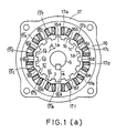
- Fig. 1 (a) is an example of the three-phase reluctance-type motor to which this invention is applied, and is a plan view showing the structure of the salient poles of the rotor, the magnetic poles of the stationary armature and the armature coils.
- the width of salient poles 1a, 1b, ... of rotor 1 is 180 degrees, and they are disposed with a phase difference of 360 degrees and an equal pitch.
- Rotor 1 consists of a well-known means of laminating silicon steel plates, with rotating shaft 5 as its axis.
- magnetic poles 16a, 16b, 16c, 16d, 16e, 16f, 16a , 16b , ... 16f are disposed with their width of 180 degrees and at an equal spacing angle.
- the widths of salient poles 1a, 1b, ... and magnetic poles 16a, ... are 180 degrees and equal.
- the number of salient poles is 14, and the number of the magnetic poles is 12.
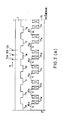
- Fig. 2 (a) is a development of the reluctance-type three-phase motor in Fig. 1 (a), and is shown till 180 degrees in mechanical angle with the remainder being omitted.
- Salient poles 1a , 1b , ... and magnetic poles 16a , 16b , ... in Fig. 1 (a) are omitted, but these are at positions which are axially symmetrical with salient poles 1a, 1b, ... and magnetic poles 16a, 16b, ... respectively.
- the magnetic attraction forces in the radial direction are balanced, producing an action that the generation of mechanical vibrations and the pressing force to bearings are made very small.
- Coils 10a, 10b and 10c in Fig. 2 (a) are position detecting elements for detecting the positions of salient poles 1a, 1b, ... which are fixed at the stationary armature 16 side in the positions shown, and the coil faces are opposed to the sides of salient poles 1a, 1b, ... via an air-gap therebetween.
- a device for obtaining position detecting signals from coils 10a, 10b and 10c there is shown a device for obtaining position detecting signals from coils 10a, 10b and 10c.
- Coil 10a and resistors 15a, 15b and 15c constitute a bridge circuit, which is adjusted so that it balances when coil 10a is not opposed to salient poles 1a, 1b, ...
- the outputs of the low-pass filters consisting of diode 11a and capacitor 12a and of diode 11b and capacitor 12b are equal, and thus the output of operational amplifier 13 becomes a low level.
- oscillator 7 an oscillation of about 1 megacycles is performed. If coil 10a is opposed to salient poles 1a, 1b, ..., impedance decreases because of iron loss (eddy-current loss plus hysteresis loss), and thus the voltage drop of resistor 15a becomes large, causing the output of operational amplifier 13 to be a high level.
- iron loss eddy-current loss plus hysteresis loss
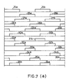
- the inputs to block circuit 9 are curves 25a, 25b, ... in the time chart of Fig. 7 (a), and the inputs through inverting circuit 13d are curves 26a, 26b, ...
- Block circuits 7a and 7b in Fig. 4 show such bridge circuits which include coils 10b and 10c, respectively.
- Oscillator 7 can commonly be used.
- Block circuit 9 is a circuit which is commonly used by the control circuit of a three-phase, Y-connection semiconductor motor, and is a logical circuit by which electrical signals of rectangular waves having a width of 120 degrees are obtained from terminals 9a, 9b, 9c, ..., 9f upon the input- ting of the above-mentioned position detecting signals.
- the outputs of terminals 9a, 9b and 9c are shown as curves 31a, 31b, ..., curves 32a, 32b, ..., and curves 33a, 33b, ..., respectively.
- the outputs of terminals 9d, 9e and 9f are shown as curves 34a, 34b, ..., curves 35a, 35b, ..., and curves 36a, 36b, ..., respectively.
- the phase differences between the output signals of terminals 9a and 9b, between the output signals of terminals 9d and 9e, and between the output signals of terminals 9c and 9f are 180 degrees.
- the output signals of terminals 9a, 9b and 9c sequentially delay by 120 degrees without being superposed, and the output signals of terminals 9d, 9e and 9f sequentially delay by 120 degrees as well.
- a reluctance-type motor has the disadvantages stated below.
- the torque is remarkably large in the initial stage in which salient poles start to oppose magnetic poles, and small in the final stage. Accordingly, there is a defect that the composite torque includes a large ripple torque. To remove such defect, for instance, the following means is effective.
- Curves 14d, 14c, 14b and 14a are the example for armature currents of 0.5 amperes, 1.0 ampere, 1.5 amperes and 2.0 amperes, respectively.
- the width of position detecting signal 31a in the time chart of Fig. 5 (c), as indicated by arrow 3c, is 120 degrees, and when the energization of an armature coil is started at the beginning thereof, the rise is delayed by large inductance as shown by dotted line 7b, and when the armature coil is de-energized at the end of the position detecting signal, the width of the falling portion becomes large because of the discharge of the large stored magnetic energy, as shown by the right end of dotted line 7b.
- the torque decreases as the rise delays, and if the falling portion exceeds the right end of arrow 3d indicating the width of 180 degrees, a counter-torque is caused. Its effect becomes remarkable when the speed is high.
- a reluctance-type motor to enhance the output torque, it is required to increase the number of the magnetic and salient poles in Fig.1 (a) and reduce the opposing air-gap between the two.
- the rise gradient of the exciting current becomes relatively gentle because of the magnetic energy stored in magnetic poles 16a, 16b, ... and salient poles 1a, 1b, ... in Fig. 1, and even if the energization is stopped, the time for the discharge current due to the magnetic energy to disappear is relatively prolonged and thus a large counter-torque occurs.
- circular portion 16 and magnetic poles 16a, 16b, ... are constructed by a well-known means of laminating and solidifying silicon steel plates, and they are fixed to outer casing 17 thereby to form the armature.
- Magnetic core 16 forms a magnetic path. Magnetic core 16 and magnetic poles 16a, 16b, ... constitute the armature.
- the salient poles are 14 in number, and have an equal width and spacing angle.
- the width of magnetic poles 16a, 16b, ... is equal to the salient pole width, and the 12 magnetic poles are disposed with an equal pitch.
- armature coils 17b and 17b When they further rotate, armature coils 17b and 17b are de-energized and armature coils 17d and 17d are energized, so that a torque by salient poles 1d and 1d occurs.
- This provides a three-phase reluctance motor in which rotor 1 is driven in the direction of arrow A.
- Armature coils 17a and 17a are connected in series or in parallel. Armature coils 17b and 17b and the other armature coils 17c, 17c , ... are also connected in a similar manner.
- transistors 20a and 20b, 20c and 20d, and 20e and 20f are inserted, respectively.
- Transistors 20a, 20b, 20c, ... act as switching elements, and other semiconductors having the same effect may be employed instead of them.
- Power is supplied from the positive and negative terminals 2a and 2b of a D.C. power supply.
- transistors 20a and 20b conduct when a high level electrical signal is inputted from terminal 4a, thereby energizing armature coils 17a and 17a .
- transistors 20c and 20d transistors 20e and 20f conduct, thereby energizing armature coils 17c, 17c , 17e and 17e .
- Block circuits D, E and F are the energization control circuits for armature coils 17b, 17b and 17d, 17d and 17f, 17f , and have the same structure as that of the energization control circuit for armature coil 17a, 17a .
- Terminal 40 is a reference voltage for specifying the armature current. By changing the voltage of terminal 40, the output torque can be changed.
- Resistors 22a and 22b are resistors for detecting the armature currents of armature coils 17a, 17a , 17c, 17c , 17e, 17e and 17b, 17b , 17d, 17d , 17f, 17f , respectively.
- the input signals to terminal 4a are position detecting signals 31a, 31b, ... in Fig. 7 (a), and the input signals to terminals 4b and 4c are position detecting signals 32a, 32b, ... and 33a, 33b, ..., respectively.
- position detecting signals 36a, 36b, ..., 34a, 34b, ..., and 35a, 35b, ... are inputted to terminals 4d, 4e and 4f in Fig. 6 (b), respectively.
- Position detecting signal 31a is shown by same symbol in Fig. 5 (c).
- the armature current increases as shown by dotted line 7b. Because of large inductance in a reluctance-type motor, the rise of dotted line 7b at the beginning of curve 31a is slow.
- the magnetic energy stored in armature coils 17a and 17a is discharged through diode 21a, transistor 20b and resistor 22a, and when the discharge current decreases to a predetermined value, the output returns to a high level again by the hysteresys characteristics of operational amplifier 40a, and transistors 20a and 20b turn on again, thereby increasing the armature current.
- position detecting signal curve 32a of Fig. 5 (b) has already been inputted to terminal 4b of Fig. 6 (b), and thus the stored magnetic energy of armature coils 17a and 17a changes to the magnetic energy of armature coils 17c and 17c , thereby making the rise of the armature current (the left end of dotted line 37b of Fig. 5 (b)) rapid.
- Capacitor 47a is effective when there are timing differences in turn-on and turn-off transistors, but it is not always necessary.
- the width of arrow 37 indicates the width of the fall and rise of dotted lines 37a and 37b. If the width of arrow 37 exceeds a predetermined angle, a counter-torque occurs and the torque also decreases. Since the widths of curves 32a and 33a become small as the speed becomes high, the width of arrow 37 also needs to be made small accordingly. This object is accomplished by diode 41a preventing the stored magnetic energy of armature coils 17a and 17a from flowing into power supply 2a, 2b.
- the width of arrow 37 is about 20 microseconds according to actual measurement, and there is an effect that a rotational speed faster than 100,000 revolutions can be obtained.
- the applied voltage becomes a high voltage due to a counter-electromotive force.
- the apparatus of this invention is characterized in that the limit of high-speed rotation and the output torque are independently controlled by the applied voltage and the reference voltage (the command voltage of the output voltage), respectively.
- the control of the control current by the position detecting signals of armature coils 17c and 17c changes by the chopper action of operational amplifier 40a and AND circuit 43b in Fig. 6 (b) in response to turn-on/off of transistor 20c, as shown by dotted line 37b of Fig. 5 (b), and rapidly falls at the end of curve 32a as shown by a dotted line.
- the armature coils are sequentially energized to generate an output torque.
- the above-mentioned energization mode is referred to as the energization mode of the A-phase.
- Position detecting signals 36a, 36b, ..., 34a, 34b, ..., and 35a, 35b, ... in Fig. 7 (a) are inputted to terminals 4d, 4e and 4f in Fig. 6 (b), respectively, thereby to control the energization of armature coils 17b, 17b , 17d, 17d , 17f, 17f included in block circuits D, E and F.
- curves 36a, 34a and 35a are shown. These are adjoining with a width of 120 degrees and delaying in phase by 60 degrees from the upper curves.
- the dotted line portions of curves 36a, 34a and 35a represent armature currents.
- the widths of the rising and falling portions are restricted by diode 41b and capacitor 47b as in the energization mode of the A-phase.
- the energization control of armature coils 17b, 17b , 17d, 17d , 17f, 17f by curves 36a, 36b, ..., 34a, 34b, ... and 35a, 35b, ... is referred to as the energization mode of the B-phase.
- the energization modes of the first, second and third phases are general expressions, they are divided into two in this specification and referred to as the energization modes of the A-phase and B-phase.
- the end of curve 31a is the point of dotted line 42c, and the section between dotted lines 42a and 42c is the energization section of armature coils 17a, 17a .
- the characteristics and section of the flat portion of the torque can be altered by changing the shapes of the opposing magnetic poles and salient poles, and thus it is needed to change the position of dotted line 42a accordingly.
- the width between dotted line 42a and the beginning of the torque curve is 10 to 20 degrees.
- position detecting signal curves 31a, 31b, ... curves 32a, 32b, ... and curves 33a, 33b, ... in Fig. 7 (a) perform the energization control of a width of 120 degrees of armature coils 17a, 17a , 17c, 17c , 17e, 17e , and position detecting signal curves 36a, 36b, ..., curves 34a, 34b, ... and curves 35a, 35b perform the energization control of a width of 120 degrees of armature coils 17b, 17b , 17d, 17d , 17f, 17f .
- the ripple voltage of power supply terminals 2a and 2b in Fig. 6 (b) is not related so much, and thus a capacitor of a small capacity may be used for rectification, and the rectifying capacitor has still smaller capacity for a three-phase A.C. power supply, thereby providing a characteristic feature that the power supply can be simplified.
- Fig. 1 (b) is a plan view of a two-phase reluctance-type motor
- Fig. 2 (b) is a development of the salient poles, magnetic poles and armature coils thereof.
- circular portion 16 and magnetic poles 16a, 16b, ... are made by a well-known means for laminating and solidifying silicon steel plates, and fixed to an outer casing, not shown, to form an armature.
- Magnetic core 16 is a magnetic path.
- Armature coils 17a and 17b are wound around magnetic poles 16a and 16b. Other armature coils are omitted and not shown.
- rotating shaft 5 is supported for rotation, to which rotor 1 is fixed.
- Rotor 1 On the outer periphery of rotor 1, salient poles 1a, 1b, ... are provided and opposed to magnetic poles 16a, 16b, ... with an air-gap of about 0.1 to 0.2 millimeters therebetween. Rotor 1 is also made by the same means as armature 16. The development of this is shown in Fig. 2 (b).
- the salient poles are 10 in number, and have an equal width and spacing angle.
- the width of magnetic poles 16, 16b, ... is equal to the width of the salient poles, and eight magnetic poles are disposed with an equal pitch.
- Arrow 18a shows an exciting polarity of rotating by 90 degrees from the state as shown, and magnetic poles 16b and 16c become the N-pole and magnetic poles 16f and 16g become the S-pole.
- the magnetization of such polarities is to make the counter-torque due to magnetic flux leakage small.
- rotor 1 rotates in the direction of arrow A, providing a two-phase motor.
- the width between the individual magnetic poles is 1.5 times the salient pole width.
- a reluctance-type motor Since a reluctance-type motor has no field magnet, it is required to increase the magnetic flux generated by the magnetic poles even to cover the magnetic flux by the field magnet. Accordingly, the large space between the magnetic poles has important meaning.
- the number of magnetic poles in Fig. 2 (b) is 10, which is larger than the conventional well-known one of this type. Consequently, a counter-torque is generated by the discharge of the magnetic energy stored in the individual magnetic poles by excitation and the output torque becomes large, but there remains a problem of reduction in the rotational speed, thereby making it impossible to put it to practical use.
- the description of the generation of the driving torque of rotor 1 provided above is for an armature coil energization angle of 180 degrees.
- the means of this invention uses an energization angle of 90 degrees, but the rotation principle is completely the same.
- armature coils K and L represent armature coil 17a, 17e and 17c, 17g in Fig. 2 (b), respectively, and the two sets of armature coils are connected in series or parallel.
- transistors 20a, 20b and 20c, 20d are inserted, respectively.
- Transistors 20a, 20b, 20c and 20d act as switching elements, and other semiconductor elements having the same effect may be used instead.
- Power is supplied from the positive and negative terminals 2a and 2b of a D.C. power supply.
- transistors 20a and 20b conduct, whereby armature coil K is energized.
- transistors 20c and 20d When a high-level electrical signal is inputted from terminal 4c, transistors 20c and 20d conduct, whereby armature coil L is energized.
- Coil 8a and 8b in Fig. 2 (b) have the same construction as coil 10a in Fig. 2 (a), and are fixed to the armature side so as to oppose to the side faces of salient poles 1a, 1b, ...
- Coils 8a and 8b are opposed to the side faces of salient poles 1a, 1b, ... through an air-gap as shown in Fig. 2 (b), and this arrangement makes the impedance of the coils small because of iron loss (which includes eddy-current loss, and this loss is large). Coils 8a and 8b are spaced apart by (360 + 90) degrees.
- FIG. 3 an arrangement for obtaining position detecting signals from coils 8a and 8b is shown.
- Coils 8a and 8b, and resistors 15a, 15b, 15c and 15d constitute a bridge circuit.
- the output frequency of oscillator circuit 7 is about 1 megacycles.
- Coils 8a and 8b are air-core coils which are fixed to the stationary armature side, and when opposed to salient poles 1a, 1b, ... in Fig. 2 (b), their impedance decreases because of eddy-current loss and the voltage drop of resistor 15a increases.
- the output of operational amplifier 13a is a rectangular wave output having a width of 180 degrees, and such signal is shown in the time chart of Fig. 7 (b) as curves 70a, 70b, ...
- the voltage drop in resistor 15c is inputted to the - terminals of operational amplifiers 13a and 13b.
- the output of terminal 6a becomes the above described curves 70a, 70b, ..., and the output of terminal 6b becomes curves 72a, 72b, ..., and the width of each curve is 180 degrees.
- the outputs of terminals 6c and 6d through an inverting circuit are curves 73a, 73b, ... and curves 74a, 74b, ...
- curves 72a, 72b, ... and curves 70a, 70b, ... curves 83a, 83b, ... are obtained by the same means.
- curves 84a, 84b, ... are obtained from curves 72a, 72b, ... and 73a, 73b, ..., and curves 85a, 85b, ... from curves 73a, 73b, ... and curves 74a, 74b, ...
- armature coils K and L are armature coils 17a, 17e and 17c, 17g.
- Block circuit c is an energization control circuit including armature coils M and N, and has the completely same construction as those of armature coils K and L.
- Armature coils M and N indicate a series or parallel connecting body of armature coils 17b and 17f, and a similar connecting body of armature coils 17d and 17h, respectively.
- each of the armature coils is energized for 90 degrees in the sequence of armature coil K ⁇ M ⁇ L ⁇ N.
- Position detecting signal curves 82a, 83a, 84a and 85a are shown in Fig. 5 (a) by the same symbols.
- a chopper circuit repeating such cycle is constructed. Since both transistors 20a and 20b turn off at the end of position detecting signal 82a, the stored magnetic energy of armature coil K charges capacitor 47 via diodes 21a and 21b.
- Capacitor 47 may be a capacitor of a small capacity. With a capacitor of a small capacity, the charging current rises more rapidly and the rise of the energization of armature coil M becomes more rapid, and simultaneously the width of the falling portion of armature coil K (the width of arrow 23 in Fig. 5 (a)) can be made small.
- Diode 41 is to prevent the stored magnetic energy from flowing into the power supply and eliminating the above described action.
- a chopper action providing a current value restricted by reference voltage 40 is attained.
- the pulsating current portion of the armature current by the chopper action is omitted and not shown.
- Dotted curves 23a, 23b, 23c and 23d of time chart in Fig. 5 (a) are the armature current curves of armature coils K, M, L and N, respectively.
- the width of arrow 23 can be made 20 microseconds for a motor of a 300-watt output, and thus a high-speed rotation can be achieved.
- a high torque is provided if the height of curve 23a is increased, and to this end, it is only needed to apply a voltage exceeding the counter-electromotive force between terminals 2a and 2b as in the case of an ordinary D.C. motor.
- the width of the section between dotted lines 42a and 42b is 90 degrees.
- the energization mode may be considered to be only the A-phase or the B-phase.
- the same object can also be attained by providing diodes 41, 41a and 41b of Figs. 6 (a) and (b) at the negative electrode 2b side of the power supply.
- the present invention is utilized for the drive source of industrial equipment as a highly efficient D.C. motor of a large output torque and less torque ripple, and particularly as a servo motor.
Abstract
Description
- This invention is related to a reluctance-type electric motor which is used for the drive source of industrial equipment as a highly efficient D.C. motor of a large output torque and less torque ripple, and which is particularly effective when used as a servo motor.
- Traditionally, the number of the phases cannot be made so large in a reluctance-type motor as in a typical commutator motor. This is because practicability is lost since the cost of the semiconductor circuit of each phase is high.
- Accordingly, the stored magnetic energy of each magnetic pole becomes large and it takes time to discharge and store it, and thus there is a problem that the torque becomes high but the speed does not.
- Further, particularly in a reluctance-type motor having a large output torque, the number of the magnetic poles of the armature becomes large and the air-gap of the magnetic path thereof is small, so that the stored magnetic energy is large, whereby the above-mentioned inconvenience is accelerated.
- The higher the torque, the more impossible the solution of this problem.
- Next, because of the large inductance of armature coils, there is a problem that the rise and fall times of the armature current increase thereby to make the ripple of the output torque large.
- Moreover, there is a problem that the efficiency is also degraded.
- Accordingly, it is the object of this invention to provide a reluctance-type motor which is high-speed, highly efficient, small-sized and inexpensive.
- This invention is characterized in that in a two-phase reluctance-type motor wherein, when the armature coils of each phase are energized with a fixed current, the torque becomes maximum in the vicinity of 10 to 20 degrees in electrical angle since the salient poles of the rotor start to enter the magnetic poles and thereafter a flat torque is obtained only for a predetermined section, a reluctance-type motor the ripple torque of which has been removed comprising: a position detecting unit including position detecting elements for detecting positions of salient poles by which a first, second, third and fourth single-phase position detecting signals are obtained in which there are disposed continuous position detecting signals having a width of 90 degrees in electrical angle that are not superposed in time, semiconductor switching elements connected to both ends of 1st, 1st, 2nd and 2nd armature coils when the armature coils of a 1st and 2nd phases are formed into said 1st and 1st armature coils and said 2nd and 2nd armature coils, respectively, diodes which are reversely connected to the series connecting body of said respective semiconductor switching elements and said armature coils, energization control circuit which makes said semiconductor switching elements conductive by means of said 1st, 2nd, 3rd and 4th position detecting signals to energize said 1st, 2nd, 1st and 2nd armature coils, thereby generating an output torque in one direction, a d.c. power supply for supplying power to said energization control circuit via one diode forwardly inserted in the positive or negative electrode side of said power supply, means for adjusting the fixing positions of said position detecting elements to initiate the energization of each said armature coil from the vicinity where the torque becomes maximum, a chopper circuit for holding the armature current at a preset value, and an electric circuit which, when said armature coil being controlled for energization by a position detecting signal is de-energized at the end of said position detecting signal, prevents the magnetic energy stored in said armature coil from being fed back to said D.C. power supply via the reversely connected diodes by means of the one diode forwardly inserted in the power supply side, and converts said magnetic energy to the stored magnetic energy of said armature coil to be energized next, thereby making the rise and fall of said armature current rapid.
- This invention is further characterized in that in a three-phase reluctance-type motor wherein, when the armature coils of each phase are energized with a fixed current, the torque becomes maximum in the vicinity of 10 to 20 degrees in electrical angle since the salient poles of the rotor start to enter the magnetic poles and thereafter a flat torque is obtained only for a predetermined section, a reluctance-type motor the ripple torque of which has been removed comprising: a position detecting unit including position detecting elements for detecting the positions of the salient poles by which the position detecting signals of an A-phase having disposed therein a continuous 1st, 2nd and 3rd position detecting signals of a width of 120 degrees in electrical angle that are not superposed in time are obtained, and by which the position detecting signals of a B-phase having disposed therein a 4th, 5th and 6th position detecting signals that have a phase dif-ference of 60 degrees in electrical angle from the 1st, 2nd and 3rd position detecting signals are obtained, semiconductor switching elements connectedto both ends of 1st, 1st, 2nd, 2nd, 3rd and 3rd armature coils when the armature coils of first, second and third phases are formed into said 1st, 1st armature coils, 2nd, 2nd armature coils and 3rd, 3rd armature coils, respec-tively, diodes which reversely connected to the series connecting body of said respective semiconductor switching elements and said armature coils, a first energization control circuit which makes said semiconductor switching elements conductive by means of said 1st, 2nd and 3rd position detecting signals to energize said 1st, 2nd and 3rd armature coils, respectively, thereby generating an output torque in one direction, a second energization control circuit which makes said semiconductor switching elements conductive by means of said 4th, 5th and 6th position detecting signals to energize said 1st, 2nd and 3rd armature coils, respectively, thereby generating a torque in the same direction, a D.C. power supply for supplying power to said first and second energization control circuits via a first and second diodes which are forwardly inserted in the positive or negative electrode said of said power supply, means for adjusting the fixing positions of said position detecting elements to initiate the energization of each said armature coil from the vicinity where the torque becomes maximum, a chopper circuit for holding the armature current at a preset value, and an electric circuit which, when the armature coils being energized by said 1st, 2nd and 3rd position detecting signals are de -energized at the end of said position detecting signals, prevents the magnetic energy stored in said armature coils from being fed back to said D.C. power supply via said reversely connected diodes by means of said first diode, and converts said magnetic energy to the stored magnetic energy of said armature coil to be energized next, and which, when said armature coils being energized by said 4th, 5th and 6thposition detecting signals are de-energized at the end of said position detecting signals, prevents the magnetic energy stored in said armature coils from being fed back to said D.C. power supply via said reversely connected diodes by means of said second diode, and converts said magnetic energy to the magnetic energy of said armature coil to be energized next, thereby mak- ing the rise and fall of said armature current rapid.
- In accordance with this invention, in a certain section of a position detecting signals, by holding the armature current at a preset value, and at end thereof, by converting the stored magnetic energy of the armature coil to the stored magnetic energy of the armature coil to be energized next, the discharge current is rapidly extinguished, and simultaneously the rise of the energization current of the next armature coil is made rapid. Accordingly, a high-speed and high-torque motor can be provided.
- For the above described action, power is supplied from the applied D.C. power supply through a forwardly connected diode, and in addition, a capacitor connected in parallel with the power supply is used if necessary.
- Well-known means for providing a high speed and high torque achieves the object by increasing the applied voltage, but this means inconveniently degrades the efficiency. In addition, a limit is also imposed on the high speed, and generally a speed higher than 10,000 revolutions per minute is impossible.
- In accordance with the means of this invention, the rise of the energization current in the beginning of a position detection signal and the width of the falling current in the end of the position detecting signal can be made small as described above, and thus there is an action that the generation of reduction in torque and counter-torque can be suppressed, whereby a motor of about 100,000 revolutions per minute is obtained.
- Since delay of the energization of an armature coil due to large inductance is removed, the energization can be performed with a preset current for the width of a position detecting signal.
- Consequently, by adjusting the fixing position of the position detecting elements, the energization can be executed only of the sections in which the torque is flat, and thus there is an action that the torque ripple of the output torque is removed and a highly efficient motor is obtained.
- Even if the power supply voltage is low, a fast and highly efficient reluctance-type motor is achieved.
- For a single-phase A.C. power supply, the capacity of a capacitor (for smoothing) may be made small as compared with the prior art.
- For a three-phase a.c. power supply, the smoothing capacitor further becomes so small that the power supply is simplified.
- By making the armature coils of a single phase or dividing them into an A-phase and a B-phase, the energization control circuit is simplified, and becomes small-sized and inexpensive.
- Fig. 1 (a) is an explanatory view of the structure of a three-phase reluctance-type motor, Fig. 1 (b) is an explanatory view of the structure of a two-phase reluctance-type motor, Fig. 2 is a development of the rotor, magnetic poles and armature coils of the three-phase and two-phase motors, Figs. 3 and 4 are electric circuits for obtaining position detecting signals from the coils, Fig. 5 is a time chart of position detecting signal curves, armature currents and output torques, Fig. 6 is an energization control circuit of the armature coils, and Fig. 7 is a time chart of the position detecting signals.
- Now, this invention is described according to its embodiment with reference to the drawings.
- Hereinafter angles are all designated in electrical angle.
- Fig. 1 (a) is an example of the three-phase reluctance-type motor to which this invention is applied, and is a plan view showing the structure of the salient poles of the rotor, the magnetic poles of the stationary armature and the armature coils.
- The width of
salient poles rotor 1 is 180 degrees, and they are disposed with a phase difference of 360 degrees and an equal pitch. -
Rotor 1 consists of a well-known means of laminating silicon steel plates, with rotating shaft 5 as its axis. - In
stationary armature 16,magnetic poles - The widths of
salient poles magnetic poles 16a, ... are 180 degrees and equal. The number of salient poles is 14, and the number of the magnetic poles is 12. - Fig. 2 (a) is a development of the reluctance-type three-phase motor in Fig. 1 (a), and is shown till 180 degrees in mechanical angle with the remainder being omitted.
-
Salient poles magnetic poles salient poles magnetic poles -
Coils salient poles stationary armature 16 side in the positions shown, and the coil faces are opposed to the sides ofsalient poles -
Coils - In Fig. 4, there is shown a device for obtaining position detecting signals from
coils -
Coil 10a andresistors coil 10a is not opposed tosalient poles - The outputs of the low-pass filters consisting of
diode 11a andcapacitor 12a and of diode 11b andcapacitor 12b are equal, and thus the output ofoperational amplifier 13 becomes a low level. - In oscillator 7, an oscillation of about 1 megacycles is performed. If
coil 10a is opposed tosalient poles resistor 15a becomes large, causing the output ofoperational amplifier 13 to be a high level. - The inputs to
block circuit 9 arecurves circuit 13d arecurves -
Block circuits coils - Oscillator 7 can commonly be used.
- The output of
block circuit 7a and the output of invertingcircuit 13e are inputted toblock circuit 9, and those output signals are designated ascurves curves 28a, 28b, ..., respectively. - The output of
block circuit 7b and the output of invertingcircuit 13f are inputted toblock circuit 9, and those signals are shown in Fig. 7 (a) ascurves 29a, 29b, ... andcurves - From
curves curves curves curves 29a, 29b, ... delay in phase by 120 degrees. -
Block circuit 9 is a circuit which is commonly used by the control circuit of a three-phase, Y-connection semiconductor motor, and is a logical circuit by which electrical signals of rectangular waves having a width of 120 degrees are obtained fromterminals - The outputs of
terminals curves curves curves - The outputs of
terminals curves curves curves terminals terminals terminals - In addition, the output signals of
terminals terminals - The same effect is obtained by using an aluminium plate rotating synchronously with
rotor 1 in Fig. 1 (a) and having the same shape instead ofsalient poles - A reluctance-type motor has the disadvantages stated below.
- First, the torque is remarkably large in the initial stage in which salient poles start to oppose magnetic poles, and small in the final stage. Accordingly, there is a defect that the composite torque includes a large ripple torque. To remove such defect, for instance, the following means is effective.
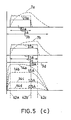
- That is, means for making the widths in the direction of the rotating shaft of the opposing faces of the salient and magnetic poles different from each other. If such means is employed, the output torque curves are made flat by the leakage fluxes of the opposing faces as shown by
curves 14a, 14b, ... in Fig. 5 (c). -
Curves 14d, 14c, 14b and 14a are the example for armature currents of 0.5 amperes, 1.0 ampere, 1.5 amperes and 2.0 amperes, respectively. - In consequence, by selecting the energization width of the armature coils and the point at which the energization starts, the output torque ripple can be removed.
- This is one means of this invention. Second, there is a drawback that the efficiency degrades.
- The width of
position detecting signal 31a in the time chart of Fig. 5 (c), as indicated byarrow 3c, is 120 degrees, and when the energization of an armature coil is started at the beginning thereof, the rise is delayed by large inductance as shown by dottedline 7b, and when the armature coil is de-energized at the end of the position detecting signal, the width of the falling portion becomes large because of the discharge of the large stored magnetic energy, as shown by the right end of dottedline 7b. - The torque decreases as the rise delays, and if the falling portion exceeds the right end of
arrow 3d indicating the width of 180 degrees, a counter-torque is caused. Its effect becomes remarkable when the speed is high. - Accordingly, the rotational speed becomes low, and the efficiency degrades for a high speed.
- To make the rise and fall of the armature currents rapid for preventing the degradation of the efficiency at a high speed is one means of this invention.
- Third, there is a disadvantage that the rotational speed becomes very small if the output torque is made large, that is, the number of salient and magnetic poles is increased to increase the exciting current.
- Generally, in a reluctance-type motor, to enhance the output torque, it is required to increase the number of the magnetic and salient poles in Fig.1 (a) and reduce the opposing air-gap between the two.
- If, at this time, the number of revolutions is held at a required value, the rise gradient of the exciting current becomes relatively gentle because of the magnetic energy stored in
magnetic poles salient poles - Under such circumstances, the peak value of the armature current become small and a counter-torque occurs, causing a disadvantage that the rotational speed becomes a small value.
- In accordance with the means of this invention, the rise and fall of the armature current becomes rapid, by which the above described disadvantages are removed.
- In the developments of Figs. 1 (a) and 2 (a),
circular portion 16 andmagnetic poles outer casing 17 thereby to form the armature. -
Magnetic core 16 forms a magnetic path.Magnetic core 16 andmagnetic poles - The salient poles are 14 in number, and have an equal width and spacing angle. The width of
magnetic poles - When armature coils 17b, 17c, 17b and 17c are energized,
salient poles - When they further rotate, armature coils 17b and 17b are de-energized and
armature coils salient poles - Each
time rotor 1 rotates by 60 degrees, the energization mode of armature coils is changed, and the excited magnetic poles of the magnetic poles are cyclically altered:magnetic poles magnetic poles magnetic poles magnetic poles rotor 1 is driven in the direction of arrow A. - Since two magnetic poles to be excited are always heteropolar, the magnetic fluxes passing through the unexcited magnetic poles are of the directions opposite to each other, whereby the generation of a counter-torque is prevented.
- The means for energizing
armature coils - Armature coils 17a and 17a are connected in series or in parallel. Armature coils 17b and 17b and the
other armature coils - In Fig. 6 (b), at both ends of
armature coils transistors -
Transistors - Power is supplied from the positive and
negative terminals 2a and 2b of a D.C. power supply. - If the lower input of AND
circuit 43a is a high level,transistors armature coils - If high level electrical signals are inputted from
terminals 4b and 4c,transistors 20d transistors 20e and 20f conduct, thereby energizingarmature coils - Block circuits D, E and F are the energization control circuits for
armature coils armature coil - Accordingly, if high-level inputs are provided to
terminals 4d, 4e and 4f when the lower inputs of ANDcircuits -
Terminal 40 is a reference voltage for specifying the armature current. By changing the voltage ofterminal 40, the output torque can be changed. - When the power supply switch (not shown) is turned on, the output of op-
erational amplifier 40a becomes a high level because the - terminal of oper-ational amplifier 40a is lower than the + terminal, andtransistors armature coils Resistors
ofarmature coils - The situation is completely same for
operational amplifier 40b, and a voltage is applied to block circuits D, E and F simultaneously with the turn-on of the power supply. - The input signals to terminal 4a are
position detecting signals terminals 4b and 4c areposition detecting signals - The above-mentioned curves are shown by the same symbols in the time chart of Fig. 5 (b).
Curves - In addition,
position detecting signals terminals 4d, 4e and 4f in Fig. 6 (b), respectively. - In Fig. 5 (b), curves 36a (same as 36b), 34a, 35a, ... are shown and they are continuing without being superposed.
- An explanation is made on the case that position detecting
signal curve 31a of Fig. 5 (b) is inputted to terminal 4a of Fig. 6 (b). -
Position detecting signal 31a is shown by same symbol in Fig. 5 (c). - The armature current increases as shown by dotted
line 7b. Because of large inductance in a reluctance-type motor, the rise ofdotted line 7b at the beginning ofcurve 31a is slow. - It is therefore necessary to increase the applied voltage to terminal 2a. Since the width of
curve 31a decreases as the speed becomes high, a higher voltage should be used accordingly as the voltage of terminal 2a. - When the armature current exceeds a preset value (specified by the reference voltage of
terminal 40 in Fig. 6 (b)), the output ofoperational amplifier 40a becomes a low level, and thus the output of ANDcircuit 43a becomes a low level, wherebytransistor 20a is turned off. - Accordingly, the magnetic energy stored in
armature coils diode 21a,transistor 20b andresistor 22a, and when the discharge current decreases to a predetermined value, the output returns to a high level again by the hysteresys characteristics ofoperational amplifier 40a, andtransistors - When the armature current increases to the preset value restricted by
reference voltage 40, the output ofoperational amplifier 40a becomes a low level, andtransistor 20a turns off, thereby decreasing the armature current. A chopper circuit repeating such cycle is provided, and the section ofarrow 3c in Fig. 5 (c) is passed. - At the end of
curve 31a, the input to terminal 4a in Fig. 6 (b) disappears. Consequently, since bothtransistors armature coil diode 21b→capacitor 47a→ resistor22a→diode 21a, thereby chargingcapacitor 47a. - At this time, however, position detecting
signal curve 32a of Fig. 5 (b) has already been inputted to terminal 4b of Fig. 6 (b), and thus the stored magnetic energy ofarmature coils armature coils line 37b of Fig. 5 (b)) rapid. -
Capacitor 47a is effective when there are timing differences in turn-on and turn-off transistors, but it is not always necessary. - The width of
arrow 37 indicates the width of the fall and rise ofdotted lines arrow 37 exceeds a predetermined angle, a counter-torque occurs and the torque also decreases. Since the widths ofcurves arrow 37 also needs to be made small accordingly. This object is accomplished bydiode 41a preventing the stored magnetic energy ofarmature coils power supply 2a, 2b. - If there is not
diode 41a and the magnetic energy ofarmature coils line 37a becomes large and the applied voltage to armaturecoils power supply 2a, 2b, so that the width of the rising portion of dotted line also becomes large. - Accordingly, a motor of a high speed can be obtained. It is of course possible to accomplish the same object by increasing the power supply voltage, but this means results in a high-voltage power supply which has a problem in practical use, and thus the means according to this invention is effective.
- In order to obtain a speed of 10,000 revolutions per minute for motor having an output of 300 watts, a voltage of the order of 150 volts is required for
terminals 2a and 2b if there is notdiode 41a, but the use ofdiode 41a provides an action and effect that such voltage only needs to be 60 volts. - In this case, the width of
arrow 37 is about 20 microseconds according to actual measurement, and there is an effect that a rotational speed faster than 100,000 revolutions can be obtained. In this instance, the applied voltage becomes a high voltage due to a counter-electromotive force. - Further, to increase the output torque, it is only needed to increase the voltage of
reference voltage 40 in Fig. 6 (b). - As described above, the apparatus of this invention is characterized in that the limit of high-speed rotation and the output torque are independently controlled by the applied voltage and the reference voltage (the command voltage of the output voltage), respectively.
- The control of the control current by the position detecting signals of
armature coils operational amplifier 40a and ANDcircuit 43b in Fig. 6 (b) in response to turn-on/off oftransistor 20c, as shown by dottedline 37b of Fig. 5 (b), and rapidly falls at the end ofcurve 32a as shown by a dotted line. - Then, when
position detecting signal 33a is inputted to terminal 4c in Fig. 6 (b), the energization ofarmature coils - As stated above, the armature coils are sequentially energized to generate an output torque.
- The above-mentioned energization mode is referred to as the energization mode of the A-phase.
-
Position detecting signals terminals 4d, 4e and 4f in Fig. 6 (b), respectively, thereby to control the energization ofarmature coils - In Fig. 5 (b), curves 36a, 34a and 35a are shown. These are adjoining with a width of 120 degrees and delaying in phase by 60 degrees from the upper curves.
- The dotted line portions of
curves diode 41b andcapacitor 47b as in the energization mode of the A-phase. - In addition, the chopper control of the intermediate portion of each curve by AND
circuits operational amplifier 40b andreference voltage terminal 40 is also similar to the energization mode of the A-phase. The action and effect is similar as well. - The energization control of
armature coils curves - Although, in a three-phase motor such as this embodiment, the energization modes of the first, second and third phases are general expressions, they are divided into two in this specification and referred to as the energization modes of the A-phase and B-phase.
- Because of the energization modes of the A-phase and B-phase, only two sets of chopper circuits for armature current control are needed, and the use of
diodes - In Fig. 5 (c), as stated before, the torque curves of the individual armature coils in the constant-current energization of 180 degrees are shown as
curves 14a, 14b, ... - The fixing positions of
coils signal curve 31a of Fig. 5 (c) is set to the point ofdotted line 42a, that is, the point at which the torque curve starts to be flat. - The end of
curve 31a is the point ofdotted line 42c, and the section betweendotted lines armature coils - As previously stated, since the rise and fall of the energization curve are rapid, the output torque becomes flat.
- Although the torque decreases at the final stage of the energization if curve 14a and the armature current are large, the flatness of the output torque becomes better as the armature current is smaller.
- The above described circumstances are completely the same for the output torques of the corresponding armature coils by other position detecting coils.
- There is therefore an effect that the torque ripple of the composite torque is removed.
- If used as a servo motor, it is in the vicinity of the stop point of a load that flatness is required.
- At this time, the output torque has decreased and thus the armature current is small and the torque curves of the energization currents below
curves 14a and 14b of Fig. 5 (c) are applied, so that the torque becomes flat. - Since the energization section of armature coils is also the section of the maximum value of the torque, the efficiency is also good.
- As to the shapes of
torque curves 14a, 14b, ..., the characteristics and section of the flat portion of the torque can be altered by changing the shapes of the opposing magnetic poles and salient poles, and thus it is needed to change the position of dottedline 42a accordingly. - According to the common means, the width between
dotted line 42a and the beginning of the torque curve is 10 to 20 degrees. - As understood from the above description, position detecting
signal curves armature coils signal curves armature coils - Since it is only the reference voltage (the voltage of
terminal 40 of Fig. 6 (b)) that specifies the output torque or armature current value, the applied voltage ripple has no effect. - Accordingly, the ripple voltage of
power supply terminals 2a and 2b in Fig. 6 (b) is not related so much, and thus a capacitor of a small capacity may be used for rectification, and the rectifying capacitor has still smaller capacity for a three-phase A.C. power supply, thereby providing a characteristic feature that the power supply can be simplified. - The above described circumstances are the same for the rectifying capacitor in the later described embodiment as well.
- Next, a description is made to the case that this invention is applied to a two-phase reluctance-type motor.
- Fig. 1 (b) is a plan view of a two-phase reluctance-type motor, and Fig. 2 (b) is a development of the salient poles, magnetic poles and armature coils thereof.
- In Fig. 1 (b),
circular portion 16 andmagnetic poles Magnetic core 16 is a magnetic path. - Armature coils 17a and 17b are wound around
magnetic poles - By a bearing provided in the outer casing, rotating shaft 5 is supported for rotation, to which
rotor 1 is fixed. - On the outer periphery of
rotor 1,salient poles magnetic poles Rotor 1 is also made by the same means asarmature 16. The development of this is shown in Fig. 2 (b). - In Fig. 2 (b), the salient poles are 10 in number, and have an equal width and spacing angle.
- The width of
magnetic poles - When armature coils 17b, 17f, 17c and 17g are energized,
salient poles - When they further rotate, the energization of armature coils 17b and 17f is stopped and armature
coils armature coils salient poles - Arrow 18a shows an exciting polarity of rotating by 90 degrees from the state as shown, and
magnetic poles magnetic poles - During the next rotation of 90 degrees or arrow 18b, the individual magnetic poles take the N- and S-poles as shown. "0" represents unexcited ones.
- In the next rotation of 90 degrees and the subsequent rotation of 90 degrees, magnetization is made to the polarities shown by
arrows 18c and 18d. - By the above described excitation,
rotor 1 rotates in the direction of arrow A, providing a two-phase motor. - The width between the individual magnetic poles is 1.5 times the salient pole width.
- In addition, since the space in which the armature coils are mounted is large, a thick wire can be utilized to provide an effect that copper loss is reduced for increasing the efficiency.
- Since a reluctance-type motor has no field magnet, it is required to increase the magnetic flux generated by the magnetic poles even to cover the magnetic flux by the field magnet. Accordingly, the large space between the magnetic poles has important meaning.
- The number of magnetic poles in Fig. 2 (b) is 10, which is larger than the conventional well-known one of this type. Consequently, a counter-torque is generated by the discharge of the magnetic energy stored in the individual magnetic poles by excitation and the output torque becomes large, but there remains a problem of reduction in the rotational speed, thereby making it impossible to put it to practical use.
- In accordance with the means of this invention, however, the above stated inconvenience is removed and only the effect of increasing the output torque is added. Its details are described later on.
- The description of the generation of the driving torque of
rotor 1 provided above is for an armature coil energization angle of 180 degrees. The means of this invention uses an energization angle of 90 degrees, but the rotation principle is completely the same. - In Fig. 6 (a), armature coils K and L represent
armature coil - At both ends of armature coils K and L,
transistors -
Transistors - Power is supplied from the positive and
negative terminals 2a and 2b of a D.C. power supply. When a high-level electrical signal is inputted from terminal 4a,transistors - When a high-level electrical signal is inputted from terminal 4c,
transistors - The means for obtaining position detecting signals is now described.
-
Coil coil 10a in Fig. 2 (a), and are fixed to the armature side so as to oppose to the side faces ofsalient poles -
Coils salient poles Coils - In Fig. 3, an arrangement for obtaining position detecting signals from
coils -
Coils resistors - The output frequency of oscillator circuit 7 is about 1 megacycles.
-
Coils salient poles resistor 15a increases. - When
coil 8a faces a salient pole, an electrical signal smoothed by a low-pass filter consisting ofdiode 11a andcapacitor 12a is inputted to the + terminal of operational amplifier 13a. - Also, for the voltage drop in
resistor 15b, an electrical signal which was changed to a d.c. current by a low-pass filter consisting of diode 11b andcapacitor 12b is inputted to the + terminal ofoperational amplifier 13b. Since an adjustment was previously made so that the bridge circuit balances whencoils operational amplifiers 13a and 13b do not exist at this time. - When
coil 8a faces a salient pole, the output of operational amplifier 13a is a rectangular wave output having a width of 180 degrees, and such signal is shown in the time chart of Fig. 7 (b) ascurves - The voltage drop in
resistor 15c is inputted to the - terminals ofoperational amplifiers 13a and 13b. The output ofterminal 6a becomes the above describedcurves terminal 6b becomescurves 72a, 72b, ..., and the width of each curve is 180 degrees. - The outputs of
terminals curves - When the superposed portions of the signals of
curves - Also for
curves 72a, 72b, ... and curves 70a, 70b, ..., curves 83a, 83b, ... are obtained by the same means. - By a similar means, curves 84a, 84b, ... are obtained from
curves 72a, 72b, ... and 73a, 73b, ..., and curves 85a, 85b, ... fromcurves - The above position detecting signals are used for the circuit of Fig. 6 (a).
- Now, the armature coils controlled for energization by the above described two-phase position detecting signals are described according to Fig. 6 (a).
- As stated above, armature coils K and L are
armature coils - Armature coils M and N indicate a series or parallel connecting body of armature coils 17b and 17f, and a similar connecting body of
armature coils - The above-mentioned position detecting
signal curves terminals - Accordingly, each of the armature coils is energized for 90 degrees in the sequence of armature coil K → M→ L→ N. Position detecting
signal curves - In Fig. 6 (a), if the position detecting signal of
curve 82a is inputted from terminal 4a when the power is turned on,transistors line 23. - Accordingly, if a voltage drop occurs in
resistor 22 and exceeds the voltage ofreference voltage 40 which is the input to the + terminal ofoperational amplifier 40a, the output ofoperational amplifier 40a goes to a low level and, in turn, the output of ANDcircuit 43a also changes to a low level, so thattransistor 20a turns off. - Since
transistor 20b is conducting, the magnetic energy stored in armature coil K is discharged viadiode 21a andresistor 22. - When the voltage drop in
resistor 22 decreases and exceeds a predetermined value, the output ofoperational amplifier 40a returns to a high level because of its hysteresis characteristics. In consequence,transistor 20a turns on again and the armature current increases, and when the current restricted byreference voltage 40 is exceeded,transistor 20a turns off again. - A chopper circuit repeating such cycle is constructed. Since both
transistors position detecting signal 82a, the stored magnetic energy of armature coilK charges capacitor 47 viadiodes - Since the applied voltage of armature coil M to be energized is increased next by that charging voltage, the energizing current rapidly rises. At this time, a voltage is applied to armature coil M by position detecting
signal curve 83a of Fig. 5 (a), which is inputted to terminal 43b. -
Capacitor 47 may be a capacitor of a small capacity. With a capacitor of a small capacity, the charging current rises more rapidly and the rise of the energization of armature coil M becomes more rapid, and simultaneously the width of the falling portion of armature coil K (the width ofarrow 23 in Fig. 5 (a)) can be made small. - Since a counter-torque and reduction torque occur when the width of
arrow 23 exceeds a predetermined value, there is an action and effect that a high-speed motor is provided by making the width ofarrow 23 small. - It is considered that the conversion of the stored magnetic energy of armature coil K to the magnetic energy of armature coil M makes the width of
arrow 23 small. -
Diode 41 is to prevent the stored magnetic energy from flowing into the power supply and eliminating the above described action. - Even if
capacitor 47 is removed, the above-mentioned magnetic energy conversion can be performed more rapidly. The energization of armature coil M is performed in a manner similar to armature coil K byoperational amplifier 40a, AND circuit 43. - A chopper action providing a current value restricted by
reference voltage 40 is attained. - The pulsating current portion of the armature current by the chopper action is omitted and not shown.
- Also, when
position detecting signals terminals 4c and 4d, control of the armature current is similarly performed by ANDcircuits operational amplifier 40a, and the action and effect is also similar. - Accordingly, a torque of one direction is obtained and the motor rotates.
-
Dotted curves - The width of
arrow 23 can be made 20 microseconds for a motor of a 300-watt output, and thus a high-speed rotation can be achieved. - The reason for that is described below with reference to Fig. 5 (c).
- Since the energization control of armature coils by
position detecting signals signal curve 82a. - Since the inductance of armature coils is large as described above, if the energization is provided only for the width of
arrow 3a, the rise delays as shown by dottedline 7a, and the width of the falling portion becomes remarkably large, so that torque decreases in the rise portion, and a counter-torque occurs if the falling portion exceeds the right end ofarrow 3b of a width of 180 degrees. - Consequently, for a high-speed, the efficiency degrades and the output torque also decreases, resulting in an inconvenience that practicability is lost.
- According to the means of the present invention, such inconvenience is obviated and a motor of 100,000 revolutions per minute can efficiently be obtained.
- The widths of the rise and fall of an armature current become very small because of
diode 41 in Fig. 6 (a), whereby an armature current shown by dottedline curve 23a is provided. - Accordingly, the occurrence of a reduction torque and a counter-torque is prevented, whereby a motor having a high speed and torque can be obtained.
- A high torque is provided if the height of
curve 23a is increased, and to this end, it is only needed to apply a voltage exceeding the counter-electromotive force betweenterminals 2a and 2b as in the case of an ordinary D.C. motor. - The torque curves in the section of 180 degrees are shown by
curves 14a, 14b, ... as in the previously described three-phase motor. - If the fixing positions of
coils curve 82a is the point ofdotted line 42a, the point at which the armature current is ceased is the point ofdotted line 42b. - The width of the section between
dotted lines - Accordingly, characteristics are provided that the output torque are only the flat portions of
torque curves 14a, 14b, ... and the composite torque also become flat. - In addition, because of the energization in the section of the maximum torque, there is an effect that the efficiency increases.
- If there are air-gaps in the boundary of
curves - Although this embodiment is for a two-phase motor, the energization mode may be considered to be only the A-phase or the B-phase.
- Also, it can be considered to be an energization mode of one same phase. Accordingly, there is a characteristic feature that the energization control circuit is simplified.
- The same object can also be attained by providing
diodes negative electrode 2b side of the power supply. - In Figs. 6 (a) and (b), the same object can also be accomplished by performing the chopper control by AND
circuits operational amplifiers lower transistors - The present invention is utilized for the drive source of industrial equipment as a highly efficient D.C. motor of a large output torque and less torque ripple, and particularly as a servo motor.
Claims (2)
- In a two-phase reluctance-type motor wherein, when the armature coils of each phase are energized with a fixed current, the torque become maximum in the vicinity of 10 to 20 degrees in electrical angle since the salient poles of the rotor start to enter the magnetic poles and thereafter a flat torque is obtained only for a predetermined section, a reluctance-type motor the ripple torque of which has been removed comprising:
a position detecting unit including position detecting elements for detecting the positions of salient poles by which a first, second, third and fourth single-phase position detecting signals are obtained in which there are disposed continuous position detecting signals having a width of 90 degrees in electrical angle that are not superposed in time,
semiconductor switching elements connected to both ends of 1st, 1st, 2nd and 2nd armature coils when the armature coils of first and second phases are formed into said 1st and 1st armature coils and said 2nd and 2nd armature coils, respectively,
diodes which are reversely connected to the series connecting body of said respective semiconductor switching elements and said armature coils,
energization control circuit which makes said semiconductor switching elements conductive by means of 1st, 2nd, 3rd and 4th position detecting signals to energize said 1st, 2nd, 1st and 2nd armature coils, thereby generating an output torque in one direction,
a D.C. power supply for supplying power to said energization control circuit via one diode forwardly inserted in the positive or negative electrode side of said power supply,
means for adjusting the fixing positions of said position detecting elements to initiate the energization of each said armature coils from the vicinity where the torque becomes maximum,
a chopper circuit for holding the armature current at a preset value, and
an electric circuit which, when said armature coil being controlled for energization by a position detecting signal is de-energized at the end of said position detecting signal, prevents the magnetic energy stored in said armature coil from being fed back to said D.C. power supply via the reversely connected diodes by means of one diode forwardly inserted in the power supply side, and converts said magnetic energy to the stored magnetic energy of said armature coil to be energized next, thereby making the rise and fall of said armature current rapid. - In a three-phase reluctance-type motor wherein, when the armature coils of each are energized with a fixed current, the torque becomes maximum is the vicinity of 10 to 20 degrees in electrical angle since the salient poles of the rotor start to enter the magnetic poles and thereafter a flat torque is obtained only for a predetermined section,
a reluctance-type motor the ripple torque of which has been removed comprising:
a position detecting unit including position detecting elements for detecting the positions of the salient poles by which the position detecting signals of A-phase having disposed therein a continuous 1st, 2nd and 3rd position detecting signals of a width of 120 degrees in electrical angle that are not superposed in time are obtained, and by which the position detecting signals of a B-phase having disposed therein a 4th, 5th and 6th position detecting signals that have a phase difference of 60 degrees in electrical angle from the 1st, 2nd and 3rd position detecting signals are obtained,
semiconductor switching elements connected to both ends of 1st, 1st, 2nd, 2nd, 3rd and 3rd armature coils when the armature coils of a first, second and third phases are formed into said 1st, 1st armature coils, 2nd, 2nd armature coils and 3rd, 3rd armature coils, respectively,
diodes which are reversely connected to the series connecting body of said respective semiconductor switching elements and said armature coils,
a first energization control circuit which makes said semiconductor switching elements conductive by means of said 1st, 2nd and 3rd position detecting signals to energize said 1st, 2nd and 3rd armature coils, respectively, thereby generating an output torque in one direction,
a second energization control circuit which makes said semiconductor switching elements conductive by means of said 4th, 5th and 6th position detecting signals to energize said 1st, 2nd and 3rd armature coils, respectively, thereby generating a torque in the same direction,
a D.C. power supply for supplying power to said first and second energization control circuits via a first and second diodes which are forwardly inserted in the positive or negative electrode side of said power supply,
means for adjusting the fixing positions of said position detecting elements to initiate the energization of each said armature coil from the vicinity where the torque becomes maximum,
a chopper circuit for holding the armature current at a preset value, and
an electric circuit which, when the armature coils being energized by said 1st, 2nd and 3rd position detecting signals are de-energized at the end of said position detecting signals, prevents the magnetic energy stored in said armature coils from being fed back to said D.C. power supply via said reversely connected diodes by means of said first diode, and converts said magnetic energy to the stored magnetic energy of said armature coil to be energized next, and which, when said armature coils being energized by said 4th, 5th and 6th position detecting signals are de-energized at the end of said position detecting signals, prevents the magnetic energy stored in said armature coils from being fed back to said d.c. power supply via said reversely connected diodes by means of said second diode, and converts said magnetic energy to the magnetic energy of said armature coil to be energized next, thereby making the rise and fall of said armature current rapid.
Applications Claiming Priority (3)
| Application Number | Priority Date | Filing Date | Title |
|---|---|---|---|
| JP1200402A JPH0365094A (en) | 1989-08-03 | 1989-08-03 | Reluctance type motor from which torque ripple is removed |
| JP200402/89 | 1989-08-03 | ||
| PCT/JP1990/000988 WO1991002402A1 (en) | 1989-08-03 | 1990-08-02 | Reluctance motor |
Publications (3)
| Publication Number | Publication Date |
|---|---|
| EP0436742A1 true EP0436742A1 (en) | 1991-07-17 |
| EP0436742A4 EP0436742A4 (en) | 1992-06-03 |
| EP0436742B1 EP0436742B1 (en) | 1996-10-16 |
Family
ID=16423722
Family Applications (1)
| Application Number | Title | Priority Date | Filing Date |
|---|---|---|---|
| EP90911711A Expired - Lifetime EP0436742B1 (en) | 1989-08-03 | 1990-08-02 | Reluctance motor |
Country Status (5)
| Country | Link |
|---|---|
| US (1) | US5138244A (en) |
| EP (1) | EP0436742B1 (en) |
| JP (1) | JPH0365094A (en) |
| DE (1) | DE69028910T2 (en) |
| WO (1) | WO1991002402A1 (en) |
Families Citing this family (24)
| Publication number | Priority date | Publication date | Assignee | Title |
|---|---|---|---|---|
| JPH04109896A (en) * | 1990-08-28 | 1992-04-10 | Secoh Giken Inc | Torque ripple eliminator of reluctance-type motor |
| JPH04172986A (en) * | 1990-11-07 | 1992-06-19 | Secoh Giken Inc | High speed 3-phase dc motor |
| JPH04183294A (en) * | 1990-11-15 | 1992-06-30 | Secoh Giken Inc | Reluctance type motor |
| JPH04275096A (en) * | 1991-02-27 | 1992-09-30 | Secoh Giken Inc | Numeric controller for load |
| GB9120404D0 (en) * | 1991-09-25 | 1991-11-06 | Switched Reluctance Drives Ltd | Control of switched reluctance machines |
| DE4132881A1 (en) * | 1991-10-03 | 1993-07-29 | Papst Motoren Gmbh & Co Kg | Brushless DC motor control circuit - has circuit for phase displacement of commutation times depending on motor speed using functional relationship |
| US5327069A (en) * | 1992-06-19 | 1994-07-05 | General Electric Company | Switched reluctance machine including permanent magnet stator poles |
| US5432420A (en) * | 1992-06-29 | 1995-07-11 | Kabushikigaisha Sekogiken | Reluctance-type motor and a DC motor capable of performing regenerative braking |
| US5545964A (en) * | 1992-09-24 | 1996-08-13 | Switched Reluctance Drives Ltd. | Control of switched reluctance machines |
| US5381081A (en) * | 1993-05-27 | 1995-01-10 | General Electric Company | Switched reluctance generator for generating AC power |
| US5404091A (en) * | 1993-05-27 | 1995-04-04 | General Electric Company | Switched reluctance generator system with self-excitation capability during load faults |
| EP0758816A4 (en) * | 1994-11-09 | 1998-05-27 | Sekoh Giken Kk | Flat reluctance type three-phase motor |
| US5652493A (en) * | 1994-12-08 | 1997-07-29 | Tridelta Industries, Inc. (Magna Physics Division) | Polyphase split-phase switched reluctance motor |
| GB9524893D0 (en) * | 1995-12-05 | 1996-02-07 | Switched Reluctance Drives Ltd | Method and apparatus for producing iron losses in a switched reluctance machine |
| US5661381A (en) * | 1996-02-15 | 1997-08-26 | Dana Corporation | Apparatus for external inductance sensing for variable-reluctance motor commutation |
| GB9818878D0 (en) | 1998-08-28 | 1998-10-21 | Switched Reluctance Drives Ltd | Switched reluctance drive with high power factor |
| JP2000125585A (en) * | 1998-10-12 | 2000-04-28 | Denso Corp | Reluctance type motor |
| US6483212B1 (en) * | 1999-10-06 | 2002-11-19 | Asmo Co., Ltd. | Reluctance-type electric motor |
| GB0113776D0 (en) * | 2001-06-06 | 2001-07-25 | Switched Reluctance Drives Ltd | Excitation of switched reluctance motors |
| GB0310491D0 (en) * | 2003-05-07 | 2003-06-11 | Switched Reluctance Drives Ltd | Excitation of switched reluctance motors |
| FR2876231B1 (en) * | 2004-05-06 | 2006-12-22 | Gerard Koehler | VARIABLE RELUCTANCE ROTATING DYNAMO-ELECTRIC MACHINE WITH GLOBALIZATION OF MAGNETIC, ELECTRICAL AND POLARIZING CIRCUITS AND METHOD FOR MANUFACTURING THE SAME |
| KR100784649B1 (en) * | 2006-04-21 | 2007-12-12 | 경성대학교 산학협력단 | Single-Phase Switched Reluctance Motor Driving circuit And Driving Method thereof |
| JP5656424B2 (en) * | 2010-03-15 | 2015-01-21 | 小松 康廣 | Motor drive circuit |
| WO2015104821A1 (en) * | 2014-01-09 | 2015-07-16 | 三菱電機株式会社 | Synchronous motor drive circuit, synchronous motor driven by same, fan using this synchronous motor, air conditioner using this fan, and synchronous motor driving method |
Citations (3)
| Publication number | Priority date | Publication date | Assignee | Title |
|---|---|---|---|---|
| DE2831997A1 (en) * | 1977-07-20 | 1979-01-25 | Janome Sewing Machine Co Ltd | CONTROL DEVICE FOR A SEWING MACHINE PULSE MOTOR |
| US4164696A (en) * | 1977-08-10 | 1979-08-14 | Teletype Corporation | Stepping motor excitation |
| EP0427868A1 (en) * | 1989-05-02 | 1991-05-22 | Kabushikigaisha Sekogiken | Reluctance-type electric motor |
Family Cites Families (7)
| Publication number | Priority date | Publication date | Assignee | Title |
|---|---|---|---|---|
| JPS5418018A (en) * | 1977-07-11 | 1979-02-09 | Ricoh Co Ltd | Pulse motor drive circuit |
| JPS55127889A (en) * | 1979-03-24 | 1980-10-03 | Sony Corp | Motor-driving circuit |
| EP0180815B2 (en) * | 1984-10-19 | 1994-12-28 | Kollmorgen Corporation | Variable speed variable reluctance electrical machines |
| IE56528B1 (en) * | 1985-01-15 | 1991-08-28 | John V Byrne | Electrical drive systems incorporating variable reluctance motors |
| US4739203A (en) * | 1986-10-24 | 1988-04-19 | Shicoh Engineering Co. Ltd. | Single-phase brushless motor with cogging features |
| US4739240A (en) * | 1987-04-29 | 1988-04-19 | General Electric Company | Commutator for switched reluctance drive |
| JPH01186193A (en) * | 1988-01-19 | 1989-07-25 | Secoh Giken Inc | Reluctance type two-phase motor |
-
1989
- 1989-08-03 JP JP1200402A patent/JPH0365094A/en active Pending
-
1990
- 1990-08-02 EP EP90911711A patent/EP0436742B1/en not_active Expired - Lifetime
- 1990-08-02 DE DE69028910T patent/DE69028910T2/en not_active Expired - Fee Related
- 1990-08-02 WO PCT/JP1990/000988 patent/WO1991002402A1/en active IP Right Grant
- 1990-08-02 US US07/651,254 patent/US5138244A/en not_active Expired - Fee Related
Patent Citations (3)
| Publication number | Priority date | Publication date | Assignee | Title |
|---|---|---|---|---|
| DE2831997A1 (en) * | 1977-07-20 | 1979-01-25 | Janome Sewing Machine Co Ltd | CONTROL DEVICE FOR A SEWING MACHINE PULSE MOTOR |
| US4164696A (en) * | 1977-08-10 | 1979-08-14 | Teletype Corporation | Stepping motor excitation |
| EP0427868A1 (en) * | 1989-05-02 | 1991-05-22 | Kabushikigaisha Sekogiken | Reluctance-type electric motor |
Non-Patent Citations (3)
| Title |
|---|
| DESIGN ENGINEERING, February 1988, pages 10,14, London, GB; "Hybrid control motor combines stator with positional sensor" * |
| PATENT ABSTRACTS OF JAPAN, vol. 13, no. 474 (E-836)[3822], 26th October 1989; & JP-A-1 185 193 (SECOH GIKEN INC.) 24-07-1989 * |
| See also references of WO9102402A1 * |
Also Published As
| Publication number | Publication date |
|---|---|
| US5138244A (en) | 1992-08-11 |
| EP0436742B1 (en) | 1996-10-16 |
| JPH0365094A (en) | 1991-03-20 |
| DE69028910D1 (en) | 1996-11-21 |
| DE69028910T2 (en) | 1997-02-13 |
| WO1991002402A1 (en) | 1991-02-21 |
| EP0436742A4 (en) | 1992-06-03 |
Similar Documents
| Publication | Publication Date | Title |
|---|---|---|
| EP0436742B1 (en) | Reluctance motor | |
| US5168190A (en) | Reluctance-type motor | |
| EP0444198B1 (en) | Reluctance type motor | |
| WO1992016046A1 (en) | High-speed motor | |
| JPH0646593A (en) | High-speed reluctance type motor | |
| US5214365A (en) | Three-phase reluctance type electric motor | |
| US6369481B1 (en) | Polyphase reluctance motor | |
| JP2010115086A (en) | Motor system and energization method of permanent magnet motor | |
| JP6393843B1 (en) | Switched reluctance motor | |
| JPH04281390A (en) | High speed motor | |
| JPH0260494A (en) | Reluctance type two-phase motor | |
| JPH0421391A (en) | Forward/reverse rotating apparatus for reluctance type motor | |
| JPH0947079A (en) | Reluctance motor | |
| JPH05219788A (en) | High-speed motor | |
| JP2799868B2 (en) | Reluctance motor | |
| JP2745411B2 (en) | High speed motor | |
| JPH03117394A (en) | Reluctance type motor juxtaposed with a plurality of armatures | |
| JPH05308795A (en) | Reluctance type three-phase motor | |
| JPH05207784A (en) | Reluctance type three-phase high speed motor | |
| JPH05244795A (en) | Reluctance type two-phase high speed electric motor | |
| JPH02101988A (en) | Three-phase reluctance motor | |
| JPH02106192A (en) | Reluctance motor | |
| JPH01186193A (en) | Reluctance type two-phase motor | |
| JPH02307391A (en) | Three-phase polarized-wave reluctance motor | |
| JPH04289795A (en) | High speed motor |
Legal Events
| Date | Code | Title | Description |
|---|---|---|---|
| PUAI | Public reference made under article 153(3) epc to a published international application that has entered the european phase |
Free format text: ORIGINAL CODE: 0009012 |
|
| 17P | Request for examination filed |
Effective date: 19910423 |
|
| AK | Designated contracting states |
Kind code of ref document: A1 Designated state(s): DE FR GB |
|
| A4 | Supplementary search report drawn up and despatched |
Effective date: 19920421 |
|
| AK | Designated contracting states |
Kind code of ref document: A4 Designated state(s): DE FR GB |
|
| RAP3 | Party data changed (applicant data changed or rights of an application transferred) |
Owner name: KABUSHIKIGAISHA SEKOGIKEN |
|
| 17Q | First examination report despatched |
Effective date: 19940322 |
|
| GRAG | Despatch of communication of intention to grant |
Free format text: ORIGINAL CODE: EPIDOS AGRA |
|
| GRAH | Despatch of communication of intention to grant a patent |
Free format text: ORIGINAL CODE: EPIDOS IGRA |
|
| GRAH | Despatch of communication of intention to grant a patent |
Free format text: ORIGINAL CODE: EPIDOS IGRA |
|
| GRAA | (expected) grant |
Free format text: ORIGINAL CODE: 0009210 |
|
| AK | Designated contracting states |
Kind code of ref document: B1 Designated state(s): DE FR GB |
|
| REF | Corresponds to: |
Ref document number: 69028910 Country of ref document: DE Date of ref document: 19961121 |
|
| ET | Fr: translation filed | ||
| PGFP | Annual fee paid to national office [announced via postgrant information from national office to epo] |
Ref country code: GB Payment date: 19970724 Year of fee payment: 8 |
|
| PGFP | Annual fee paid to national office [announced via postgrant information from national office to epo] |
Ref country code: FR Payment date: 19970811 Year of fee payment: 8 Ref country code: DE Payment date: 19970811 Year of fee payment: 8 |
|
| PLBE | No opposition filed within time limit |
Free format text: ORIGINAL CODE: 0009261 |
|
| STAA | Information on the status of an ep patent application or granted ep patent |
Free format text: STATUS: NO OPPOSITION FILED WITHIN TIME LIMIT |
|
| 26N | No opposition filed | ||
| PG25 | Lapsed in a contracting state [announced via postgrant information from national office to epo] |
Ref country code: GB Free format text: LAPSE BECAUSE OF NON-PAYMENT OF DUE FEES Effective date: 19980802 |
|
| GBPC | Gb: european patent ceased through non-payment of renewal fee |
Effective date: 19980802 |
|
| PG25 | Lapsed in a contracting state [announced via postgrant information from national office to epo] |
Ref country code: FR Free format text: LAPSE BECAUSE OF NON-PAYMENT OF DUE FEES Effective date: 19990430 |
|
| PG25 | Lapsed in a contracting state [announced via postgrant information from national office to epo] |
Ref country code: DE Free format text: LAPSE BECAUSE OF NON-PAYMENT OF DUE FEES Effective date: 19990601 |
|
| REG | Reference to a national code |
Ref country code: FR Ref legal event code: ST |