EP0436718B1 - Method of charging ore in melt-reduction - Google Patents
Method of charging ore in melt-reduction Download PDFInfo
- Publication number
- EP0436718B1 EP0436718B1 EP88907777A EP88907777A EP0436718B1 EP 0436718 B1 EP0436718 B1 EP 0436718B1 EP 88907777 A EP88907777 A EP 88907777A EP 88907777 A EP88907777 A EP 88907777A EP 0436718 B1 EP0436718 B1 EP 0436718B1
- Authority
- EP
- European Patent Office
- Prior art keywords
- furnace
- ores
- chute
- charging
- coal
- Prior art date
- Legal status (The legal status is an assumption and is not a legal conclusion. Google has not performed a legal analysis and makes no representation as to the accuracy of the status listed.)
- Expired - Lifetime
Links
Images

Classifications
-
- C—CHEMISTRY; METALLURGY
- C22—METALLURGY; FERROUS OR NON-FERROUS ALLOYS; TREATMENT OF ALLOYS OR NON-FERROUS METALS
- C22B—PRODUCTION AND REFINING OF METALS; PRETREATMENT OF RAW MATERIALS
- C22B34/00—Obtaining refractory metals
- C22B34/30—Obtaining chromium, molybdenum or tungsten
- C22B34/32—Obtaining chromium
-
- C—CHEMISTRY; METALLURGY
- C21—METALLURGY OF IRON
- C21B—MANUFACTURE OF IRON OR STEEL
- C21B13/00—Making spongy iron or liquid steel, by direct processes
- C21B13/0006—Making spongy iron or liquid steel, by direct processes obtaining iron or steel in a molten state
-
- C—CHEMISTRY; METALLURGY
- C21—METALLURGY OF IRON
- C21C—PROCESSING OF PIG-IRON, e.g. REFINING, MANUFACTURE OF WROUGHT-IRON OR STEEL; TREATMENT IN MOLTEN STATE OF FERROUS ALLOYS
- C21C5/00—Manufacture of carbon-steel, e.g. plain mild steel, medium carbon steel or cast steel or stainless steel
- C21C5/005—Manufacture of stainless steel
-
- C—CHEMISTRY; METALLURGY
- C21—METALLURGY OF IRON
- C21C—PROCESSING OF PIG-IRON, e.g. REFINING, MANUFACTURE OF WROUGHT-IRON OR STEEL; TREATMENT IN MOLTEN STATE OF FERROUS ALLOYS
- C21C5/00—Manufacture of carbon-steel, e.g. plain mild steel, medium carbon steel or cast steel or stainless steel
- C21C5/28—Manufacture of steel in the converter
- C21C5/30—Regulating or controlling the blowing
- C21C5/35—Blowing from above and through the bath
-
- C—CHEMISTRY; METALLURGY
- C22—METALLURGY; FERROUS OR NON-FERROUS ALLOYS; TREATMENT OF ALLOYS OR NON-FERROUS METALS
- C22B—PRODUCTION AND REFINING OF METALS; PRETREATMENT OF RAW MATERIALS
- C22B5/00—General methods of reducing to metals
- C22B5/02—Dry methods smelting of sulfides or formation of mattes
- C22B5/10—Dry methods smelting of sulfides or formation of mattes by solid carbonaceous reducing agents
-
- F—MECHANICAL ENGINEERING; LIGHTING; HEATING; WEAPONS; BLASTING
- F27—FURNACES; KILNS; OVENS; RETORTS
- F27D—DETAILS OR ACCESSORIES OF FURNACES, KILNS, OVENS, OR RETORTS, IN SO FAR AS THEY ARE OF KINDS OCCURRING IN MORE THAN ONE KIND OF FURNACE
- F27D3/00—Charging; Discharging; Manipulation of charge
- F27D3/0025—Charging or loading melting furnaces with material in the solid state
-
- F—MECHANICAL ENGINEERING; LIGHTING; HEATING; WEAPONS; BLASTING
- F27—FURNACES; KILNS; OVENS; RETORTS
- F27D—DETAILS OR ACCESSORIES OF FURNACES, KILNS, OVENS, OR RETORTS, IN SO FAR AS THEY ARE OF KINDS OCCURRING IN MORE THAN ONE KIND OF FURNACE
- F27D3/00—Charging; Discharging; Manipulation of charge
- F27D3/10—Charging directly from hoppers or shoots
-
- F—MECHANICAL ENGINEERING; LIGHTING; HEATING; WEAPONS; BLASTING
- F27—FURNACES; KILNS; OVENS; RETORTS
- F27B—FURNACES, KILNS, OVENS, OR RETORTS IN GENERAL; OPEN SINTERING OR LIKE APPARATUS
- F27B3/00—Hearth-type furnaces, e.g. of reverberatory type; Tank furnaces
- F27B3/08—Hearth-type furnaces, e.g. of reverberatory type; Tank furnaces heated electrically, with or without any other source of heat
- F27B3/085—Arc furnaces
-
- F—MECHANICAL ENGINEERING; LIGHTING; HEATING; WEAPONS; BLASTING
- F27—FURNACES; KILNS; OVENS; RETORTS
- F27D—DETAILS OR ACCESSORIES OF FURNACES, KILNS, OVENS, OR RETORTS, IN SO FAR AS THEY ARE OF KINDS OCCURRING IN MORE THAN ONE KIND OF FURNACE
- F27D3/00—Charging; Discharging; Manipulation of charge
- F27D3/16—Introducing a fluid jet or current into the charge
-
- F—MECHANICAL ENGINEERING; LIGHTING; HEATING; WEAPONS; BLASTING
- F27—FURNACES; KILNS; OVENS; RETORTS
- F27D—DETAILS OR ACCESSORIES OF FURNACES, KILNS, OVENS, OR RETORTS, IN SO FAR AS THEY ARE OF KINDS OCCURRING IN MORE THAN ONE KIND OF FURNACE
- F27D99/00—Subject matter not provided for in other groups of this subclass
- F27D99/0073—Seals
- F27D99/0075—Gas curtain seals
-
- F—MECHANICAL ENGINEERING; LIGHTING; HEATING; WEAPONS; BLASTING
- F27—FURNACES; KILNS; OVENS; RETORTS
- F27M—INDEXING SCHEME RELATING TO ASPECTS OF THE CHARGES OR FURNACES, KILNS, OVENS OR RETORTS
- F27M2001/00—Composition, conformation or state of the charge
- F27M2001/16—Particulate material, e.g. comminuted scrap
Definitions
- the present invention relates to a method of charging powder CR ore raw materials, iron ores and coal in a smelting reduction furnace.
- JP-A-61 279 609 discloses a method of charging chromium raw material, carboneous material and fluxing agent out of a bunker via a pipe into a furnace.
- EP-A-79 182 describes a furnace comprising a hopper system for charging iron ore and carboneous material into a converter type smelting reduction furnace.
- High Cr steel as stainless steel has been conventionally produced from ferrochromium as raw material.
- a so-called smelting reduction method has been recently remarked, which directly obtains high Cr molten metal from Cr ores.
- Cr ores, coal and so on are charged into a reduction furnace of a converter type for reducing Cr so as to directly produce high Cr molten metal therefrom.
- Cr raw ores are very fine in grain diameters, and ordinarily around 90% contain those having grain diameters of not more than 1 mm. Therefore, when powder Cr raw ores are charged into the reduction furnace from its top part onto the bath, they are lost up to 30% by upflowing gas.
- the object of the present invention is to provide a method of charging ores, carbonaceous material as checking their flying losses in the smelting reduction method of Cr ores, iron ores and so on.
- 1 is a furnace body, 6, 6' chutes.
- Fig.1 shows one embodiment of the invention in the smelting reduction of Cr ore, where the reference numeral 1 is the furnace body, and 2 is an exhausting hood provided at a top part of the furnace body.
- the gases are blown from a top blowing lance 3, a side blowing tuyere 4 and a bottom blowing tuyere 5 for carrying out the smelting reduction.
- the powder Cr raw ores are supplied by the chute 6 extending through the exhaust hood 2 to nearly the furnace mouth.
- the charging chute 6 is determined at a height of its lower end so that it does not contact the furnace body when the furnace is tilted.
- Fig.2 shows that the powder Cr and raw ores are charged via a chute 6′ connected to the upper part of the furnace body 1, and also in this case the same effect could be obtained.
- the charging chute 6′ may be seperated at a part 61 on the way, and when the furnace body is tilted, this part 61 is seperated.
- the powder Cr raw ores may be charged into the furnace, thereby to enable to exactly avoid the flying losses of the raw materials.
- the gas is jetted from the nozzle provided in the circumferential direction within the chute toward the outside of the chute, the powder Cr ores are guided in the gas jetting direction and the ore flying is exactly avoided.
- the jet gas also serves as a purge gas for preventing invasion of CO and CO2 of the furnace into the chute.
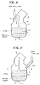
- Fig.6 shows a further embodiment of the invention in the smelting reduction of the iron ores, where the iron ores and the coal are charged into the furnace from the chute 6.
- Other structures are the same as illustrated in Fig.1.
- Fig.7 shows that the iron ores and the coal are charged via the chute 6′ connected to the top part of the furnace body 1, and the structure is the same as illustrated in Fig.2.
- the iron ores and the coal may be charged into the furnace, thereby to enable to exactly check the flying losses of the raw materials.
- the smelting reduction was carried out as charging the powder Cr raw ores into the smelting reduction furnace (capacity: 5 ton) of the converter type by the method as shown in Fig.1.
- the dispersion in grain diameters of the charged Cr raw ores are as follows. +1mm +0.5mm +0.25mm +0.149mm -0.149mm 1.7% 3.8% 20.1% 42.9% 31.5%
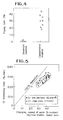
- Fig.4 shows the flying losses of Cr raw ores at the above charging in comparison with the case (comparative method) not using the charging chute, from which it is seen that the flying losses of Cr raw ores were considerably decreased by the present invention method.
- Fig.5 investigates Cr reducing rate (Cr increasing rate in the molten metal) when grain Cr raw ores were charged as they were, and the pelletized Cr raw ores were charged, from which it is seen that the former is shorter to pre-heat the ores, and is faster to reduce Cr than the latter.
- the smelting reduction was carried out as charging the Cr iron ores and the coal into the smelting reduction furnace (capacity: 5 ton) of the converter type by the method as shown in Fig.6.
- the comparative method did not use the charging chute as shown in Fig.6, and practised the smelting reduction while charging the raw materials.
- the producing conditions are as follows.
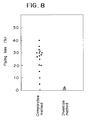
- Fig.8 shows the flying losses of the coal in comparison with the case not using the chute (the comparative method), from which it is seen that the flying losses of the coal was decreased considerably by the present invention method.
- the present invention is useful to charging of raw materials or the coal as the carbonaceous materials in the smelting reduction of the Cr ores or the iron ores.
Landscapes
- Engineering & Computer Science (AREA)
- Chemical & Material Sciences (AREA)
- Manufacturing & Machinery (AREA)
- Materials Engineering (AREA)
- Metallurgy (AREA)
- Organic Chemistry (AREA)
- Mechanical Engineering (AREA)
- General Engineering & Computer Science (AREA)
- Manufacture Of Iron (AREA)
- Carbon Steel Or Casting Steel Manufacturing (AREA)
Abstract
Description
- The present invention relates to a method of charging powder CR ore raw materials, iron ores and coal in a smelting reduction furnace.
- JP-A-61 279 609 discloses a method of charging chromium raw material, carboneous material and fluxing agent out of a bunker via a pipe into a furnace.
- EP-A-79 182 describes a furnace comprising a hopper system for charging iron ore and carboneous material into a converter type smelting reduction furnace.
- High Cr steel as stainless steel has been conventionally produced from ferrochromium as raw material. In view of saving energy and securing low production cost, a so-called smelting reduction method has been recently remarked, which directly obtains high Cr molten metal from Cr ores. In this method, Cr ores, coal and so on are charged into a reduction furnace of a converter type for reducing Cr so as to directly produce high Cr molten metal therefrom.
- Cr raw ores are very fine in grain diameters, and ordinarily around 90% contain those having grain diameters of not more than 1 mm. Therefore, when powder Cr raw ores are charged into the reduction furnace from its top part onto the bath, they are lost up to 30% by upflowing gas.
- For avoiding flying losses, an injection charging may be suggested, but special facilities are required independently therefor, and transporting pipes are easily injured by hard Cr ores Thus, such measures could not be adopted actually.
- In view of these circumstances, Cr raw ores are formed into pellets or briquets, inviting high production costs. If the ores are agglomerated, specific surface areas of the ores are made small so that a pre-heating time is made long and the reduction rate is lowered to lengthen the treatment time.
- On the other hand, as an iron making method in place of the furnace production, the smelting reduction method of iron ores has been remarked as stated above in view of saving the energy and securing the low production cost.
- In this smelting reduction method of iron ores, the flying loss of ores is not a big problem because the ores are coarse, but the coal as combustion fuel is flied and lost considerably. According to the inventors' studies, why yield of the coal is inferior in the top charge method, is because the coal is broken by rapid increasing of temperature. Since the coal has volatility and the interior of the smelting furnace is at very high temperature (more than 1400°C), the coal charged by top charge method abruptly becomes high temperature and cracked, and parts of fine powders generated by the heat cracking are exhausted out of the furnace together with the exhausted gas. The flying of the coal makes unit consumption of carbonaceous materials deteriorate in the smelting reduction of the iron ores.
- The object of the present invention is to provide a method of charging ores, carbonaceous material as checking their flying losses in the smelting reduction method of Cr ores, iron ores and so on.
- The object is solved by the features of the
claims 1 and 2. - Figs.1 to 5 concern the smelting reduction of Cr ores, and Fig.1 explains one embodiment of the invention; Fig.2 explains another embodiment of the invention; Fig.3 explains a gas jetting from an end of the charging chute; Fig.4 investigates the flying losses of grain Cr raw ores of the invention method and the comparative method; Fig.5 investigates Cr increasing rate in the molten metal when powder Cr raw ores are charged and pelletized Cr raw ores are charged;
- Figs.6 to 8 concern the smelting reduction of iron ores; Fig.6 explains a further embodiment of the invention; Fig.7 explains a still further embodiment of the invention; and Fig.8 investigates the flying losses of grain Cr raw ores of the invention method and the comparative method.
- In the drawings, 1 is a furnace body, 6, 6' chutes.
- The invention will be explained in detail.
- Fig.1 shows one embodiment of the invention in the smelting reduction of Cr ore, where the reference numeral 1 is the furnace body, and 2 is an exhausting hood provided at a top part of the furnace body. As the smelting reduction method by the converter type, there have been various proposals or studies which are different in the gas blowing practices. For example, as shown in Fig.1, the gases are blown from a top blowing
lance 3, aside blowing tuyere 4 and abottom blowing tuyere 5 for carrying out the smelting reduction. - During the treatment, Cr ores are supplied together with carbonaceous materials, and in the invention, the powder Cr raw ores are supplied by the
chute 6 extending through theexhaust hood 2 to nearly the furnace mouth. - The
charging chute 6 is determined at a height of its lower end so that it does not contact the furnace body when the furnace is tilted. - Fig.2 shows that the powder Cr and raw ores are charged via a
chute 6′ connected to the upper part of the furnace body 1, and also in this case the same effect could be obtained. - The
charging chute 6′ may be seperated at apart 61 on the way, and when the furnace body is tilted, thispart 61 is seperated. - For charging Cr ores through the
chute nozzle 7 provided in a circumferential direction of the inner part around the chute as shown in Fig.3, the powder Cr raw ores may be charged into the furnace, thereby to enable to exactly avoid the flying losses of the raw materials. - If the gas is jetted from the nozzle provided in the circumferential direction within the chute toward the outside of the chute, the powder Cr ores are guided in the gas jetting direction and the ore flying is exactly avoided. Besides, the jet gas also serves as a purge gas for preventing invasion of CO and CO₂ of the furnace into the chute.
- Fig.6 shows a further embodiment of the invention in the smelting reduction of the iron ores, where the iron ores and the coal are charged into the furnace from the
chute 6. Other structures are the same as illustrated in Fig.1. - Fig.7 shows that the iron ores and the coal are charged via the
chute 6′ connected to the top part of the furnace body 1, and the structure is the same as illustrated in Fig.2. - In the above mentioned chargings of the iron ores and the coal by the
chute nozzle 7 provided in a circumferential direction of the inner part in vicinity of the chute as shown in Fig.3, the iron ores and the coal may be charged into the furnace, thereby to enable to exactly check the flying losses of the raw materials. - The smelting reduction was carried out as charging the powder Cr raw ores into the smelting reduction furnace (capacity: 5 ton) of the converter type by the method as shown in Fig.1. The dispersion in grain diameters of the charged Cr raw ores are as follows.
+1mm +0.5mm +0.25mm +0.149mm -0.149mm 1.7% 3.8% 20.1% 42.9% 31.5% - Fig.4 shows the flying losses of Cr raw ores at the above charging in comparison with the case (comparative method) not using the charging chute, from which it is seen that the flying losses of Cr raw ores were considerably decreased by the present invention method.
- Fig.5 investigates Cr reducing rate (Cr increasing rate in the molten metal) when grain Cr raw ores were charged as they were, and the pelletized Cr raw ores were charged, from which it is seen that the former is shorter to pre-heat the ores, and is faster to reduce Cr than the latter.
- The smelting reduction was carried out as charging the Cr iron ores and the coal into the smelting reduction furnace (capacity: 5 ton) of the converter type by the method as shown in Fig.6. The comparative method did not use the charging chute as shown in Fig.6, and practised the smelting reduction while charging the raw materials. The producing conditions are as follows.
Table 1 Comparative Method Invention Method O₂ for decarburization (Nm³/Hr) 1300 1300 O₂ for post combustion (Nm³/Hr) 1300 1300 Gas flow rate (m/sec) 7.7 7.7 Unit consumption of carbonaceous material (including the flying loss) (kg/molten metal ton) 950 665 Unit consumption of the flying loss of carbonaceous material (kg/molten metal) 285 0 - Fig.8 shows the flying losses of the coal in comparison with the case not using the chute (the comparative method), from which it is seen that the flying losses of the coal was decreased considerably by the present invention method.
- The present invention is useful to charging of raw materials or the coal as the carbonaceous materials in the smelting reduction of the Cr ores or the iron ores.
Claims (3)
- A method of charging raw materials in a smelting reduction of ores, using a smelting reduction furnace of a converter type, comprising charging powder Cr raw ores into a furnace through a charging chute extending in vicinity of a mouth of the furnace or connected to a furnace body, while a gas is jetted toward the outside of the chute from a nozzle provided in an circumferential direction of the inside of the chute.
- A method of charging raw materials in a smelting reduction of ores, using a smelting reduction furnace of a converter type, comprising charging iron ores and coal into a furnace through a charging chute extending in vicinity of a mouth of the furnace or connected to a furnace body, while a gas is jetted toward the outside of the chute from a nozzle provided in an circumferential direction of the inside of the chute.
- Method according to claims 1 and 2, wherein the gas jetting is provided near the end of the chute.
Applications Claiming Priority (5)
| Application Number | Priority Date | Filing Date | Title |
|---|---|---|---|
| JP22525387 | 1987-09-10 | ||
| JP225253/87 | 1987-09-10 | ||
| JP63020472A JPH01165743A (en) | 1987-09-10 | 1988-01-29 | Method for charging of material in melting reduction of ore |
| JP20472/88 | 1988-01-29 | ||
| PCT/JP1988/000911 WO1989002477A1 (en) | 1987-09-10 | 1988-09-09 | Method of charging ore in melt-reduction |
Publications (3)
| Publication Number | Publication Date |
|---|---|
| EP0436718A4 EP0436718A4 (en) | 1989-12-28 |
| EP0436718A1 EP0436718A1 (en) | 1991-07-17 |
| EP0436718B1 true EP0436718B1 (en) | 1994-07-06 |
Family
ID=27283057
Family Applications (1)
| Application Number | Title | Priority Date | Filing Date |
|---|---|---|---|
| EP88907777A Expired - Lifetime EP0436718B1 (en) | 1987-09-10 | 1988-09-09 | Method of charging ore in melt-reduction |
Country Status (2)
| Country | Link |
|---|---|
| EP (1) | EP0436718B1 (en) |
| AU (1) | AU620344B2 (en) |
Families Citing this family (1)
| Publication number | Priority date | Publication date | Assignee | Title |
|---|---|---|---|---|
| AT412786B (en) * | 2003-07-04 | 2005-07-25 | Voest Alpine Industrieanalgenb | METHOD FOR CHARGING FLUIDABLE MATERIAL AND DEVICE FOR CARRYING OUT THE METHOD |
Family Cites Families (8)
| Publication number | Priority date | Publication date | Assignee | Title |
|---|---|---|---|---|
| US2784037A (en) * | 1954-08-18 | 1957-03-05 | Rexroth Alfred | Apparatus for shooting material into cupolas |
| US3169055A (en) * | 1961-10-12 | 1965-02-09 | Stora Kopparbergs Bergslags Ab | Process for producing pig iron in rotary furnace |
| US3462263A (en) * | 1965-08-11 | 1969-08-19 | John H Walsh | Reduction of iron ore |
| JPS57143419A (en) * | 1981-02-27 | 1982-09-04 | Nippon Steel Corp | Steel making method of large quantity of generated heat |
| ZA827820B (en) * | 1981-10-30 | 1983-08-31 | British Steel Corp | Production of steel |
| US4541866A (en) * | 1984-01-26 | 1985-09-17 | Westinghouse Electric Corp. | Hot injection ladle metallurgy |
| JPS61279609A (en) * | 1985-06-05 | 1986-12-10 | Sumitomo Metal Ind Ltd | Apparatus for producing high-chromium alloy by melt reduction |
| JPS6244533A (en) * | 1985-08-19 | 1987-02-26 | Kawasaki Steel Corp | Melting-reducing refining method for metallic oxide |
-
1988
- 1988-09-09 EP EP88907777A patent/EP0436718B1/en not_active Expired - Lifetime
- 1988-09-09 AU AU23055/88A patent/AU620344B2/en not_active Ceased
Also Published As
| Publication number | Publication date |
|---|---|
| EP0436718A1 (en) | 1991-07-17 |
| AU620344B2 (en) | 1992-02-20 |
| AU2305588A (en) | 1989-04-17 |
| EP0436718A4 (en) | 1989-12-28 |
Similar Documents
| Publication | Publication Date | Title |
|---|---|---|
| EP0308925A1 (en) | Method and apparatus for smelting and reducing iron ores | |
| JP2006528732A (en) | Slag utilization process | |
| US4986847A (en) | Process and apparatus for at least temporarily simultaneously subjecting a molten metal to the action of a gas and fine-grain solid materials | |
| CN1014996B (en) | Metal-making apparatus involving smelting reduction of metallic oxides | |
| KR890010216A (en) | Reduction method and apparatus for iron ore | |
| JPS58123809A (en) | Reduction of fine grain ore containing oxide and device therefor | |
| EP0436718B1 (en) | Method of charging ore in melt-reduction | |
| EP2199414A1 (en) | Process for producing molten iron | |
| US4935054A (en) | Method of charging chromium ores in a smelting reduction | |
| US6477195B2 (en) | Process for melting sponge iron and electric-arc furnace for carrying out the process | |
| JPS58141345A (en) | Recovering method of valuable metal | |
| KR102231653B1 (en) | Charging apparatus charging material for blast furnace and charging method of the same | |
| SA00210315B1 (en) | Method and apparatus for melting a substance containing a metal | |
| JP2546018B2 (en) | A method for feeding pre-reduced iron ore into a smelting reduction furnace | |
| JPH07216430A (en) | Molten steel production method and top blowing lance for molten metal refining | |
| US4212667A (en) | Blast furnace smelting of zinc | |
| EP1380656A1 (en) | Direct melting furnace and process therefor | |
| JPS6191319A (en) | Refining method of molten steel by arc process | |
| JPH01252710A (en) | Method for operating iron bath type smelting reduction furnace | |
| CN1013452B (en) | Method of charging chromium ores in smelting reduction | |
| JPH07103410B2 (en) | Pressure stabilization device for pressurized smelting reduction furnace in smelting reduction equipment | |
| JPS6479313A (en) | Method for blowing carbonaceous material to converter | |
| JPH03229809A (en) | Device for preventing clogging of iron ore discharging pipe in pre-reduction furnace in smelting reduction equipment | |
| KR950012402B1 (en) | Fe-mn smelting reduction process and equipment | |
| JPH07138630A (en) | Device for charging powdery and granular material in metal refining furnace and charging lance |
Legal Events
| Date | Code | Title | Description |
|---|---|---|---|
| PUAI | Public reference made under article 153(3) epc to a published international application that has entered the european phase |
Free format text: ORIGINAL CODE: 0009012 |
|
| 17P | Request for examination filed |
Effective date: 19890125 |
|
| AK | Designated contracting states |
Kind code of ref document: A1 Designated state(s): AT BE DE FR GB IT NL SE |
|
| 17Q | First examination report despatched |
Effective date: 19920320 |
|
| GRAA | (expected) grant |
Free format text: ORIGINAL CODE: 0009210 |
|
| ITF | It: translation for a ep patent filed |
Owner name: BARZANO' E ZANARDO MILANO S.P.A. |
|
| AK | Designated contracting states |
Kind code of ref document: B1 Designated state(s): AT BE DE FR GB IT NL SE |
|
| REF | Corresponds to: |
Ref document number: 108212 Country of ref document: AT Date of ref document: 19940715 Kind code of ref document: T |
|
| REF | Corresponds to: |
Ref document number: 3850578 Country of ref document: DE Date of ref document: 19940811 |
|
| ET | Fr: translation filed | ||
| EAL | Se: european patent in force in sweden |
Ref document number: 88907777.2 |
|
| PLBE | No opposition filed within time limit |
Free format text: ORIGINAL CODE: 0009261 |
|
| STAA | Information on the status of an ep patent application or granted ep patent |
Free format text: STATUS: NO OPPOSITION FILED WITHIN TIME LIMIT |
|
| 26N | No opposition filed | ||
| PGFP | Annual fee paid to national office [announced via postgrant information from national office to epo] |
Ref country code: GB Payment date: 19970901 Year of fee payment: 10 |
|
| PGFP | Annual fee paid to national office [announced via postgrant information from national office to epo] |
Ref country code: FR Payment date: 19970909 Year of fee payment: 10 |
|
| PGFP | Annual fee paid to national office [announced via postgrant information from national office to epo] |
Ref country code: DE Payment date: 19970912 Year of fee payment: 10 Ref country code: AT Payment date: 19970912 Year of fee payment: 10 |
|
| PGFP | Annual fee paid to national office [announced via postgrant information from national office to epo] |
Ref country code: SE Payment date: 19970918 Year of fee payment: 10 |
|
| PGFP | Annual fee paid to national office [announced via postgrant information from national office to epo] |
Ref country code: NL Payment date: 19970929 Year of fee payment: 10 |
|
| PGFP | Annual fee paid to national office [announced via postgrant information from national office to epo] |
Ref country code: BE Payment date: 19971104 Year of fee payment: 10 |
|
| PG25 | Lapsed in a contracting state [announced via postgrant information from national office to epo] |
Ref country code: GB Free format text: LAPSE BECAUSE OF NON-PAYMENT OF DUE FEES Effective date: 19980909 Ref country code: AT Free format text: LAPSE BECAUSE OF NON-PAYMENT OF DUE FEES Effective date: 19980909 |
|
| PG25 | Lapsed in a contracting state [announced via postgrant information from national office to epo] |
Ref country code: SE Free format text: LAPSE BECAUSE OF NON-PAYMENT OF DUE FEES Effective date: 19980910 |
|
| PG25 | Lapsed in a contracting state [announced via postgrant information from national office to epo] |
Ref country code: BE Free format text: LAPSE BECAUSE OF NON-PAYMENT OF DUE FEES Effective date: 19980930 |
|
| BERE | Be: lapsed |
Owner name: NKK CORP. Effective date: 19980930 |
|
| PG25 | Lapsed in a contracting state [announced via postgrant information from national office to epo] |
Ref country code: NL Free format text: LAPSE BECAUSE OF NON-PAYMENT OF DUE FEES Effective date: 19990401 |
|
| GBPC | Gb: european patent ceased through non-payment of renewal fee |
Effective date: 19980909 |
|
| EUG | Se: european patent has lapsed |
Ref document number: 88907777.2 |
|
| PG25 | Lapsed in a contracting state [announced via postgrant information from national office to epo] |
Ref country code: FR Free format text: LAPSE BECAUSE OF NON-PAYMENT OF DUE FEES Effective date: 19990531 |
|
| NLV4 | Nl: lapsed or anulled due to non-payment of the annual fee |
Effective date: 19990401 |
|
| PG25 | Lapsed in a contracting state [announced via postgrant information from national office to epo] |
Ref country code: DE Free format text: LAPSE BECAUSE OF NON-PAYMENT OF DUE FEES Effective date: 19990701 |
|
| REG | Reference to a national code |
Ref country code: FR Ref legal event code: ST |
|
| PG25 | Lapsed in a contracting state [announced via postgrant information from national office to epo] |
Ref country code: IT Free format text: LAPSE BECAUSE OF NON-PAYMENT OF DUE FEES;WARNING: LAPSES OF ITALIAN PATENTS WITH EFFECTIVE DATE BEFORE 2007 MAY HAVE OCCURRED AT ANY TIME BEFORE 2007. THE CORRECT EFFECTIVE DATE MAY BE DIFFERENT FROM THE ONE RECORDED. Effective date: 20050909 |