EP0436685B1 - Akustische beschichtung - Google Patents
Akustische beschichtung Download PDFInfo
- Publication number
- EP0436685B1 EP0436685B1 EP90910201A EP90910201A EP0436685B1 EP 0436685 B1 EP0436685 B1 EP 0436685B1 EP 90910201 A EP90910201 A EP 90910201A EP 90910201 A EP90910201 A EP 90910201A EP 0436685 B1 EP0436685 B1 EP 0436685B1
- Authority
- EP
- European Patent Office
- Prior art keywords
- core member
- outside
- sound
- acoustic liner
- plate
- Prior art date
- Legal status (The legal status is an assumption and is not a legal conclusion. Google has not performed a legal analysis and makes no representation as to the accuracy of the status listed.)
- Expired - Lifetime
Links
- 238000010521 absorption reaction Methods 0.000 claims abstract description 20
- 229910052751 metal Inorganic materials 0.000 claims description 6
- 239000002184 metal Substances 0.000 claims description 6
- 239000011358 absorbing material Substances 0.000 claims description 4
- 230000004323 axial length Effects 0.000 claims description 4
- 229920000049 Carbon (fiber) Polymers 0.000 claims description 3
- 239000004917 carbon fiber Substances 0.000 claims description 3
- 239000000835 fiber Substances 0.000 claims description 3
- 230000000063 preceeding effect Effects 0.000 claims 1
- 239000000463 material Substances 0.000 description 15
- 238000000034 method Methods 0.000 description 6
- 239000006096 absorbing agent Substances 0.000 description 4
- 229910052782 aluminium Inorganic materials 0.000 description 4
- XAGFODPZIPBFFR-UHFFFAOYSA-N aluminium Chemical compound [Al] XAGFODPZIPBFFR-UHFFFAOYSA-N 0.000 description 4
- 239000002131 composite material Substances 0.000 description 4
- 238000010276 construction Methods 0.000 description 4
- 238000004519 manufacturing process Methods 0.000 description 4
- 239000000919 ceramic Substances 0.000 description 3
- 239000004033 plastic Substances 0.000 description 3
- 239000004593 Epoxy Substances 0.000 description 2
- 239000000853 adhesive Substances 0.000 description 2
- 230000001070 adhesive effect Effects 0.000 description 2
- 238000002485 combustion reaction Methods 0.000 description 2
- 229920000271 Kevlar® Polymers 0.000 description 1
- 239000012814 acoustic material Substances 0.000 description 1
- 230000002238 attenuated effect Effects 0.000 description 1
- 239000011248 coating agent Substances 0.000 description 1
- 238000000576 coating method Methods 0.000 description 1
- 238000005260 corrosion Methods 0.000 description 1
- 230000007797 corrosion Effects 0.000 description 1
- 238000005520 cutting process Methods 0.000 description 1
- 239000000446 fuel Substances 0.000 description 1
- 230000001788 irregular Effects 0.000 description 1
- 239000004761 kevlar Substances 0.000 description 1
- 238000012986 modification Methods 0.000 description 1
- 230000004048 modification Effects 0.000 description 1
- 239000000123 paper Substances 0.000 description 1
- 238000007493 shaping process Methods 0.000 description 1
- 239000007787 solid Substances 0.000 description 1
- 238000003466 welding Methods 0.000 description 1
Images


Classifications
-
- G—PHYSICS
- G10—MUSICAL INSTRUMENTS; ACOUSTICS
- G10K—SOUND-PRODUCING DEVICES; METHODS OR DEVICES FOR PROTECTING AGAINST, OR FOR DAMPING, NOISE OR OTHER ACOUSTIC WAVES IN GENERAL; ACOUSTICS NOT OTHERWISE PROVIDED FOR
- G10K11/00—Methods or devices for transmitting, conducting or directing sound in general; Methods or devices for protecting against, or for damping, noise or other acoustic waves in general
- G10K11/16—Methods or devices for protecting against, or for damping, noise or other acoustic waves in general
- G10K11/172—Methods or devices for protecting against, or for damping, noise or other acoustic waves in general using resonance effects
-
- F—MECHANICAL ENGINEERING; LIGHTING; HEATING; WEAPONS; BLASTING
- F02—COMBUSTION ENGINES; HOT-GAS OR COMBUSTION-PRODUCT ENGINE PLANTS
- F02K—JET-PROPULSION PLANTS
- F02K1/00—Plants characterised by the form or arrangement of the jet pipe or nozzle; Jet pipes or nozzles peculiar thereto
- F02K1/78—Other construction of jet pipes
- F02K1/82—Jet pipe walls, e.g. liners
- F02K1/827—Sound absorbing structures or liners
-
- B—PERFORMING OPERATIONS; TRANSPORTING
- B64—AIRCRAFT; AVIATION; COSMONAUTICS
- B64D—EQUIPMENT FOR FITTING IN OR TO AIRCRAFT; FLIGHT SUITS; PARACHUTES; ARRANGEMENT OR MOUNTING OF POWER PLANTS OR PROPULSION TRANSMISSIONS IN AIRCRAFT
- B64D33/00—Arrangements in aircraft of power plant parts or auxiliaries not otherwise provided for
- B64D33/02—Arrangements in aircraft of power plant parts or auxiliaries not otherwise provided for of combustion air intakes
- B64D2033/0206—Arrangements in aircraft of power plant parts or auxiliaries not otherwise provided for of combustion air intakes comprising noise reduction means, e.g. acoustic liners
-
- B—PERFORMING OPERATIONS; TRANSPORTING
- B64—AIRCRAFT; AVIATION; COSMONAUTICS
- B64D—EQUIPMENT FOR FITTING IN OR TO AIRCRAFT; FLIGHT SUITS; PARACHUTES; ARRANGEMENT OR MOUNTING OF POWER PLANTS OR PROPULSION TRANSMISSIONS IN AIRCRAFT
- B64D33/00—Arrangements in aircraft of power plant parts or auxiliaries not otherwise provided for
- B64D33/02—Arrangements in aircraft of power plant parts or auxiliaries not otherwise provided for of combustion air intakes
- B64D2033/0266—Arrangements in aircraft of power plant parts or auxiliaries not otherwise provided for of combustion air intakes specially adapted for particular type of power plants
- B64D2033/0286—Arrangements in aircraft of power plant parts or auxiliaries not otherwise provided for of combustion air intakes specially adapted for particular type of power plants for turbofan engines
-
- Y—GENERAL TAGGING OF NEW TECHNOLOGICAL DEVELOPMENTS; GENERAL TAGGING OF CROSS-SECTIONAL TECHNOLOGIES SPANNING OVER SEVERAL SECTIONS OF THE IPC; TECHNICAL SUBJECTS COVERED BY FORMER USPC CROSS-REFERENCE ART COLLECTIONS [XRACs] AND DIGESTS
- Y02—TECHNOLOGIES OR APPLICATIONS FOR MITIGATION OR ADAPTATION AGAINST CLIMATE CHANGE
- Y02T—CLIMATE CHANGE MITIGATION TECHNOLOGIES RELATED TO TRANSPORTATION
- Y02T50/00—Aeronautics or air transport
- Y02T50/60—Efficient propulsion technologies, e.g. for aircraft
Definitions
- This invention generally relates to acoustic liners, and more particularly, to annularly or circumferentially shaped acoustic liners. Even more specifically, the present invention relates to a high efficiency broad band acoustic liner of the type especially well-suited to line the interior of a duct or shroud of a jet engine.
- Acoustic liners are employed in many applications to attenuate noises generated by machinery or equipment; and, for instance, jet engines are almost universally provided with sound absorption liners or panels to attenuate sound waves produced inside the engines.
- One type of sound absorption liner commonly used in jet engines comprises a sound permeable facing sheet, a sound impermeable backing sheet and a honeycomb core interposed between these two sheets.
- Such devices are generally referred to as laminar absorbers, and one such absorber is disclosed in U.S. Patent No. 3,166,149.
- honeycomb structure is known from GB-A-2 038 410.
- honeycomb structure is used in a Helmholtz resonator.
- US-A-2 826 261 discloses an acoustic liner comprising a sound permeable inside plate and a sound impermeable outside plate, the inside and outside plates being spaced apart and forming an annular chamber therebetween. Between both plates a core member is secured in the annular chamber forming a sine wave form in the annular direction around the liner axis of the chamber. The core member and the inside plate form a multitude of varying depth sound absorption chambers to attenuate sound waves over a broad range of frequencies.
- the present invention relates to an acoustic liner comprising a sound permeable inside plate forming a first closed annulus and defining a liner axis, a sound impermeable outside plate forming a second closed annulus located outside of and extending around the first closed annulus, the inside and outside plates being spaced apart and forming an annular chamber therebetween, a core member secured in the annular chamber between the inside and outside plates, the core member extending axially along and around the liner axis and forming a sine wave form in the annular direction around said axis, said sine wave form extending comletely around the liner axis, wherein the core member and the inside plate form a multitude of varying depth sound absorption chambers to attenuate sound waves over a broad range of frequencies and wherein the core member has an axial length and, in any place perpendicular to the liner axis and along said axial length, the core member forms a sine wave form having a generally unifom height and wave
- the invention relates to a jet engine having an axially and circumferentially extending shroud defining an engine axis, a fan rotably mounted inside the shroud, a compressor and a turbine secured within the shroud, wherein an acoustic liner, as described above, circumferentially extends around the engine axis to attenuate sound waves generated in the engine.
- each of these honeycomb structures radially extends between and is secured to both the inside plates and the core member.
- a bulk sound absorbing material is located in and completely fills the outer chambers of the liner to further attentuate the sound waves.
- Figure 1 shows a gas turbine engine including a pair of acoustic liners according to the present invention.
- Figure 2 is a front view of one of the acoustic liners.
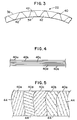
- Figure 3 is an enlarged front view of a portion of the acoustic liner.
- Figure 4 is a further enlarged view of a portion of a core member of the acoustic liner, particularly showing the laminar construction thereof.
- Figure 5 is a top view of the portion of the core member illustrated in Figure 4, with various layers partially broken away.
- Figure 6 is similar to Figure 3 but also shows a bulk sound absorption material inside the acoustic liner.
- Figure 7 is similar to Figure 3, but also shows a honeycomb structure held inside the acoustic liner.
- Figure 8 is a cross-sectional view through the honeycomb structure, taken along line VIII-VIII of Figure 7.
- Figure 9 is similar to Figure 2 and shows how the liner may be comprised of a plurality of sections.
- FIG. 1 outlines jet engine 10 generally comprising shroud or duct 12, fan 14, compressor 16, turbine 20 and acoustic liners 22 and 24.
- air is drawn into engine 10 through inlet 26 by rotating fan 14, and this air is compressed by compressor 16 and then heated in a combustion chamber by the combustion of fuel.
- the heated air is expanded through turbine 20, driving the turbine, which in turn is used to drive fan 14 and compressor 16, and the heated and expanded air is discharged from the engine through outlet 30.
- the discharged air is at a much a higher velocity than the air drawn into the engine through inlet 26, producing the desired thrust.
- shroud 12, fan 14, compressor 16 and turbine 20 are of conventional construction and operate in a conventional manner, and it is unnecessary to describe these elements further herein.
- the sound waves in the forward section of the engine are primarily generated by the rotating fan 14, and typically the frequencies of these sound waves are within a relatively narrow band, with the central frequency of that band determined principally by the rotating speed of fan 14.
- the sound waves in the rearward section of the engine are produced by compressor 16, turbine 20 and the high velocity of air moving through this area of the engine, and typically, the frequencies of these sound waves are distributed over a relatively wide range in a highly irregular manner.
- Acoustic liner 22 is secured within a forward area of engine 10 to attenuate sound waves generated in this area of the engine, and acoustic liner 24 is secured within a rearward area of the engine to attenuate sound waves produced therein.
- liner 22 extends rearward from a position adjacent inlet 26 to a position immediately forward of fan 14, and liner 24 extends forward from a position adjacent outlet 30 to a location extending around air flow guides 32 of the engine.
- Liners 22 and 24 are generally identical, and thus only one, liner 22, shown in detail in Figures 2 and 3, will be described herein in detail.
- Liner 22 includes inside plate 34, outside plate 36 and core member 40.
- inside plate 34 commonly referred to as a facing sheet
- outside plate 36 commonly referred to as a backing sheet and which preferably is sound impermeable, forms a second closed annulus that extends around and is spaced from the inside plate.
- the inside and outside plates thus form a closed annular chamber therebetween; and core member 40 is secured in this annular chamber, between plates 34 and 36.
- the core member forms a sine wave form annularly extending around the inside plate; and in this way, the inside plate and the core member form a multitude of varying depth sound absorption chambers 42 that effectively attenuate sound waves over a broad range of frequencies.
- each chamber 42 sound waves are attenuated in one or more frequency bands, each of which is centered around a particular frequency determined by the radial depth of the sound absorption at that point. Because the depth of each chamber 42 varies significantly, each chamber will effectively attenuate sound waves over a relatively wide range of frequencies.
- inside plate 34 and outside plate 36 both have substantially circular shapes, with the inside plate radially located inside of and concentric with the outside plate.
- core member 40 has a uniform wave length, over its entire circumference, with the inside peaks or edges of the wave form engaging the inside plate and with the outside peaks or edges of the wave form engaging the outside plate.
- liner 22 has a substantially cylindrical shape, with the inside plate having a substantially uniform radius, r1, over its entire length, and with the outside plate having a substantially uniform radius, r2, over its entire length.
- the shape of core member 40 is substantially uniform in the axial direction, so that the sound absorption chambers comprise axial channels extending along the entire length of the liner.
- the inside plate 34 may be fabricated from metal, plastic, ceramic, or other suitable materials; and, for instance, the inside plate may comprise a single discretely perforated metal sheet, or a combination of such a metal sheet and a porous fibrous layer, or a porous composite weave material bonded to a woven wire mesh. Depending on the specific environment in which the acoustic liner is used, it may be desirable to provide the radially inside surface of the inside plate with a corrosion resistant coating.
- the outside plate 36 may also be fabricated from metal, plastic, ceramic or other suitable materials; and for example, the outside plate may comprise a solid aluminum plate.
- Core member 40 may be made from any suitable material such as plastic, paper, metal, ceramic or from a woven composite material, and for instance, the core member may be fabricated from a flat sheet of aluminum that is bent into the desired sine wave shape. With the embodiment of liner 22 illustrated in Figures 2 and 3, the core member is constructed from a sound impermeable material, although, as discussed below, the core member may also be formed from a sound permeable material.
- Figures 4 and 5 illustrate one preferred construction of the core member, in which this member is comprised of multiple layers 40a-e of a composite material that, in turn, comprises epoxy reinforced carbon fibers 44.
- the fibers in each layer 40a-e are aligned in a particular direction; and the individual layers are placed one on top of another with the fibers of the different layers aligned in a variety of different directions to produce a composite material that has a high strength in all directions.
- the individual layers 40a-e of core member 40 may be formed in the preferred sine wave form and then secured together to form the core member. It should be noted that, while Figures 4 and 5 illustrate five individual layers, in practice it may be preferred to form the core member 40 from more layers, such as ten layers.
- Core member 40 may be secured in the annular chamber between plates 34 and 36 in any suitable manner, although preferably the radially inside peaks or edges of the core member abut against and are secured to inside plate 34, and the radially outside peaks or edges of the core member abut against and are secured to outside plate 36.
- the preferred technique for securing the core member in place generally depends on the material or materials from which that core member is made. For instance, if the core member is made from epoxy reinforced carbon fibers, then the inside and outside edges of the core member may be secured, respectively, to the inside and outside plates by an adhesive. If the core member is made from aluminum, it may be bolted, welded or mechanically interlocked to the inside and outside plates of the liner 22.
- liner 22 shown in Figures 2 and 3 to improve the sound attenuation characteristics of the acoustic liner.
- core member 40 may be made from sound permeable material, and chambers 46, which are formed by the core member and outside plate 36, may be filled with a bulk acoustic absorbing material 50.
- chambers 42 and chambers 46 of liner 22 are both used to attenuate sound waves.
- Any suitable bulk acoustic material may be used, and for example, the material may be of the type identified by the trademark Kevlar.
- sound absorption chambers 42 is filled with honeycomb structures 52.
- the walls 54 of each honeycomb structure 52 radially extend completely between inside plate 34 and core member 40, and each channel 42 is filled with a respective one of the honeycomb structures.
- These structures first, preferably prevent or inhibit sound waves from moving axially through the interior of liner 22, and second, strengthen the liner, both in the axial and radial directions.
- Honeycomb structures 52 may have any commonly used honeycomb core design and may be made of any commonly used honeycomb material, and for instance, the structures may have cell sizes in the range of 1/8 to 1/2 inch.
- Honeycomb structures 52 are preferably secured to both inside plate 34 and core member 40, and this may be done in any suitable manner such as by an adhesive.
- the length of the sine waves formed by core member 40 may vary over the circumference of the core member. For instance, this wave length may be relatively small over one portion of the core member, and comparatively large over another portion of the core member.
- liner 24 is substantially identical to liner 22.
- the principle differences between these liners relate to various parameters, such as the radial thickness of core member 40, the wave length of the sine pattern of the core member, and the specific materials from which the elements of the liner are made. As will be appreciated by those of ordinary skill in the art, these parameters are selected for each liner depending on the specific application in which the liner is used, and in particular, to help achieve the desired sound attenuation characteristics for the liner.
- Acoustic liner 22 may be assembled and secured in jet engine 10 in any suitable manner.
- the liner is comprised of three sections 22a, b and c that are formed separately and then connected together as they are placed in position in engine 10.
- Each of these liner sections includes a respective one segment of inside plate 34, outside plate 36 and core member 40 so that when these sections are connected together, they form the complete liner illustrated in Figure 2.
- These liner sections may be secured in jet engine 10 and to each other in any suitable procedure, such as by bonding, welding, bolts or by mechanical interconnections.
- each section 22a, b and c of the liner can be made by simply forming a sheet of aluminum or other suitable material into the desired sine wave shape to form a segment of the core member 40, and then placing this sine wave form between segments of the inside and outside plates. This procedure does not require any special cutting, notching or futher shaping of the core member and is not expensive or time consuming. At the same time, this technique produces the desired multiple, varying depth sound absorption chambers.
- this manufacturing procedure places very few limitations on various parameters of liner 22--such as the radial thickness of the core member and the specific materials from which the core member and inside plate 34 are made--which may be changed to vary the sound attenuation characteristics of the liner, so that this procedure can be used to construct different liners that effectively attenuate sound waves over various, broad frequency ranges.
- acoustic liners 22 and 24 have been described as being used adjacent the inlet and outlets of a jet engine.
- an acoustic liner embodying the present invention can be applied equally well to other parts of a jet engine where noise attenuation is desired or required. Indeed, this invention is not restricted to jet engines, but may also be used in any duct in which gas is flowing, or for enclosing any space in which sound waves are generated.
Landscapes
- Engineering & Computer Science (AREA)
- Chemical & Material Sciences (AREA)
- Combustion & Propulsion (AREA)
- Mechanical Engineering (AREA)
- General Engineering & Computer Science (AREA)
- Physics & Mathematics (AREA)
- Acoustics & Sound (AREA)
- Multimedia (AREA)
- Soundproofing, Sound Blocking, And Sound Damping (AREA)
- Exhaust Silencers (AREA)
Claims (11)
- Akustische Beschichtung, umfassend:
eine schalldurchlässige Innenfläche (34), die einen ersten geschlossenen Ring bildet und eine Beschichtungsachse definiert;
eine schallundurchlässige Außenfläche (36), die einen zweiten geschlossenen Ring bildet und sich außerhalb sowie um den ersten geschlossenen Ring erstreckt, wobei die Innen- und Außenflächen voneinander beabstandet sind und zwischen sich eine ringförmige Kammer bilden;
ein in der ringförmigen Kammer befestigtes Kernelement (40), das zwischen den Innen- und Außenflächen angeordnet ist und sich in axialer Richtung sowohl entlang der Beschichtungsachse als auch um die Beschichtungsachse erstreckt und in zirkularer Richtung um die Achse eine Sinuswellenform bildet, wobei sich die Sinuswellenform vollständig um die Beschichtungsachse erstreckt und das Kernelement (40) mit der Innenfläche (34) eine Vielzahl von schallabsorbierenden Kammern (42, 46) unterschiedlicher Tiefe bildet, um Schallwellen über einen breiten Frequenzbereich zu dämpfen; und
wobei das Kernelement eine axiale Länge aufweist und in jeder Ebene senkrecht zu der Beschichtungsachse und entlang der axialen Länge eine Sinuswellenform aufweist mit einer im wesentlichen einheitlichen Höhe und Wellenlänge,
gekennzeichnet durch
eine Vielzahl von Wabenstrukturen (52), die in den schallabsorbierenden Kammern (42) vorhanden sind, um die Schallwellen weiter zu dämpfen. - Akustische Beschichtung nach Anspruch 1,
dadurch gekennzeichnet,
daß das Kernelement (40) eine Vielzahl von Schichten (40a - 40e) aus verstärkten Carbonfasern (44) aufweist, und
daß die Fasern jeder Schicht im wesentlichen entlang einer entsprechenden Richtung ausgerichtet sind. - Akustische Beschichtung nach Anspruch 1 oder 2,
dadurch gekennzeichnet,
daß die geschlossene ringförmige Kammer eine Achse definiert, und
daß das Kernelement (40) eine Vielzahl von sich axial erstreckenden inneren und äußeren Kanten bildet. - Akustische Beschichtung nach Anspruch 3,
dadurch gekennzeichnet,
daß die inneren Kanten des Kernelementes (40) gegen die Innenfläche (34) stoßen und sich in axialer Richtung entlang der Innenfläche (34) erstrecken, und
daß die äußeren Kanten des Kernelementes (40) gegen die Außenfläche (36) stoßen und sich in axialer Richtung entlang der Außenfläche (36) erstrecken. - Akustische Beschichtung nach Anspruch 3 oder 4,
dadurch gekennzeichnet,
daß die inneren Kanten des Kernelementes (40) an der Innenfläche (34) befestigt sind
und
daß die äußeren Kanten des Kernelementes (40) an der Außenfläche (36) befestigt sind. - Akustische Beschichtung nach Anspruch 5,
dadurch gekennzeichnet,
daß die inneren Kanten des Kernelementes (40) an die Innenfläche (34) geklebt sind,
und
daß die äußeren Kanten des Kernelementes (40) an die Außenfläche (36) geklebt sind. - Akustische Beschichtung nach einem der Ansprüche 1 bis 6,
dadurch gekennzeichnet,
daß jede Wabenstruktur (52) sich radial vollständig zwischen der Innenfläche (34) und dem Kernelemente (40) erstreckt, und
daß jede Wabenstruktur (52) sowohl an der Innenfläche (34) als auch an dem Kernelement (40) befestigt ist. - Akustische Beschichtung nach einem der vorhergehenden Ansprüche,
gekennzeichnet durch
ein voluminöses schallabsorbierendes Material (50), das in den äußeren Kammern (46) vorhanden ist, um die Schallwellen weiter zu dämpfen. - Akustische Beschichtung nach Anspruch 8,
dadurch gekennzeichnet,
daß das voluminöse schallabsorbierende Material (50) vollständig die äußeren Kammern (46) ausfüllt. - Akustische Beschichtung nach einem der Ansprüche 1 oder 3 bis 9,
dadurch gekennzeichnet,
daß das Kernelement (40) schallundurchlässig ist und aus einer Metallplatte gefertigt ist. - Düsentriebwerk mit einer sich axial und in Umfangsrichtung erstreckenden Verkleidung (12), die eine Triebwerksachse definiert, mit einem rotierbar innerhalb der Verkleidung befestigten Gebläse (14), mit einem Kompressor (16) und einer Turbine (20), die innerhalb der Verkleidung (12) befestigt sind,
dadurch gekennzeichnet,
daß sich eine akustische Beschichtung mit den Merkmalen nach einem der Ansprüche 1 bis 10 in Umfangsrichtung um die Triebwerksachse erstreckt, um die in dem Triebwerk (10) erzeugten Schallwellen zu dämpfen.
Applications Claiming Priority (7)
| Application Number | Priority Date | Filing Date | Title |
|---|---|---|---|
| US371593 | 1989-06-26 | ||
| US07/371,593 US4969535A (en) | 1989-06-26 | 1989-06-26 | Acoustic liner |
| US371398 | 1989-06-26 | ||
| US07/371,398 US5014815A (en) | 1989-06-26 | 1989-06-26 | Acoustic liner |
| US371399 | 1989-06-26 | ||
| US07/371,399 US5025888A (en) | 1989-06-26 | 1989-06-26 | Acoustic liner |
| PCT/US1990/003538 WO1991001034A2 (en) | 1989-06-26 | 1990-06-21 | An acoustic liner |
Publications (3)
| Publication Number | Publication Date |
|---|---|
| EP0436685A1 EP0436685A1 (de) | 1991-07-17 |
| EP0436685A4 EP0436685A4 (en) | 1991-11-21 |
| EP0436685B1 true EP0436685B1 (de) | 1995-05-03 |
Family
ID=27409016
Family Applications (1)
| Application Number | Title | Priority Date | Filing Date |
|---|---|---|---|
| EP90910201A Expired - Lifetime EP0436685B1 (de) | 1989-06-26 | 1990-06-21 | Akustische beschichtung |
Country Status (5)
| Country | Link |
|---|---|
| EP (1) | EP0436685B1 (de) |
| JP (1) | JP3043402B2 (de) |
| CA (1) | CA2019802C (de) |
| DE (1) | DE69019133T2 (de) |
| WO (1) | WO1991001034A2 (de) |
Families Citing this family (6)
| Publication number | Priority date | Publication date | Assignee | Title |
|---|---|---|---|---|
| DE4131777A1 (de) * | 1991-09-24 | 1993-03-25 | Linde Ag | Fluiddurchstroemter schalldaempfer |
| IT1318059B1 (it) * | 2000-06-28 | 2003-07-21 | Aermacchi S P A | Struttura fonoassorbente e di rinforzo per pannelli acustici digondole motore. |
| US8220588B2 (en) * | 2010-03-31 | 2012-07-17 | The Boeing Company | Unitized engine nacelle structure |
| FR3022218B1 (fr) * | 2014-06-12 | 2016-07-15 | Airbus Operations Sas | Nacelle d'aeronef comprenant une entree d'air amelioree |
| US9771868B2 (en) | 2015-07-21 | 2017-09-26 | The Boeing Company | Sound attenuation apparatus and method |
| US9587563B2 (en) | 2015-07-21 | 2017-03-07 | The Boeing Company | Sound attenuation apparatus and method |
Family Cites Families (12)
| Publication number | Priority date | Publication date | Assignee | Title |
|---|---|---|---|---|
| US2419971A (en) * | 1943-06-05 | 1947-05-06 | Rumpf Herman | Padding and soundproofing material |
| BE554083A (de) * | 1956-02-18 | |||
| US2826261A (en) * | 1956-08-30 | 1958-03-11 | Oliver C Eckel | Acoustical control apparatus |
| US3599749A (en) * | 1969-07-28 | 1971-08-17 | Rohr Corp | Jet noise control system |
| GB1274343A (en) * | 1970-02-24 | 1972-05-17 | Rolls Royce | Improvements in or relating to acoustic linings |
| GB1406844A (en) * | 1972-09-01 | 1975-09-17 | Short Brothers & Harland Ltd | Sound absorbing panels |
| US3960236A (en) * | 1974-06-17 | 1976-06-01 | Mcdonnell Douglas Corporation | Lock core panel |
| JPS5312970A (en) * | 1976-07-21 | 1978-02-06 | Nissan Motor | Process for molding packing material of corrugated cardboard |
| FR2396868A1 (fr) * | 1977-07-07 | 1979-02-02 | Snecma | Garniture insonorisante pour paroi interne de conduit de gaz, notamment de conduit de turboreacteur |
| US4226299A (en) * | 1978-05-22 | 1980-10-07 | Alphadyne, Inc. | Acoustical panel |
| GB2038410B (en) * | 1978-12-27 | 1982-11-17 | Rolls Royce | Acoustic lining utilising resonance |
| US4433751A (en) * | 1981-12-09 | 1984-02-28 | Pratt & Whitney Aircraft Of Canada Limited | Sound suppressor liner |
-
1990
- 1990-06-21 DE DE69019133T patent/DE69019133T2/de not_active Expired - Fee Related
- 1990-06-21 EP EP90910201A patent/EP0436685B1/de not_active Expired - Lifetime
- 1990-06-21 JP JP2509603A patent/JP3043402B2/ja not_active Expired - Lifetime
- 1990-06-21 WO PCT/US1990/003538 patent/WO1991001034A2/en active IP Right Grant
- 1990-06-26 CA CA002019802A patent/CA2019802C/en not_active Expired - Fee Related
Also Published As
| Publication number | Publication date |
|---|---|
| EP0436685A1 (de) | 1991-07-17 |
| JPH04500401A (ja) | 1992-01-23 |
| WO1991001034A2 (en) | 1991-01-24 |
| CA2019802C (en) | 2000-11-28 |
| DE69019133D1 (de) | 1995-06-08 |
| CA2019802A1 (en) | 1990-12-26 |
| EP0436685A4 (en) | 1991-11-21 |
| WO1991001034A3 (en) | 1991-02-21 |
| JP3043402B2 (ja) | 2000-05-22 |
| DE69019133T2 (de) | 1996-01-04 |
Similar Documents
| Publication | Publication Date | Title |
|---|---|---|
| US5025888A (en) | Acoustic liner | |
| US5014815A (en) | Acoustic liner | |
| US8245815B2 (en) | Cellular-core structure for an acoustic panel | |
| CN114458453B (zh) | 连续自由度声核心 | |
| US4969535A (en) | Acoustic liner | |
| US4452335A (en) | Sound absorbing structure for a gas turbine engine | |
| US4421201A (en) | High efficiency broadband acoustic resonator and absorption panel | |
| US7124856B2 (en) | Acoustic liner for gas turbine engine | |
| US7540354B2 (en) | Micro-perforated acoustic liner | |
| US6827180B2 (en) | Noise attenuation panel | |
| US11208193B2 (en) | Sound attenuation panel for an aircraft | |
| US3507355A (en) | Multi-layer face material for sound absorptive duct lining material | |
| GB2452476A (en) | Acoustic liner for gas turbine engine manufactured by an additive fabrication process | |
| EP1356169B1 (de) | Zweischichtiger akustischer überzug und fluiddruckbeaufschlagungsvorrichtung | |
| US5060471A (en) | Jet engine noise reduction system | |
| US20160076453A1 (en) | Sound-damping arrangement for an engine nacelle and engine nacelle comprising such an arrangement | |
| US11560842B2 (en) | Acoustic panel and associated propulsion unit | |
| GB2037896A (en) | A Turbojet Engine Nozzle for Attenuating Core and Turbine Noise | |
| EP3678128B1 (de) | Schalldämpfende auskleidung und verfahren zur herstellung einer schalldämpfenden auskleidung | |
| EP0436685B1 (de) | Akustische beschichtung | |
| US4539245A (en) | Sound attenuating structure | |
| CN101636575A (zh) | 一种消音衬垫的实施方法及用此方法获得的衬垫 | |
| EP0636780A1 (de) | Lärmdämpfende Auskleidung für Strahlmotoren | |
| US20100089690A1 (en) | Method for making an acoustic treatment coating and coating thus obtained | |
| US5250764A (en) | Consecutive plate acoustic suppressor apparatus and methods |
Legal Events
| Date | Code | Title | Description |
|---|---|---|---|
| PUAI | Public reference made under article 153(3) epc to a published international application that has entered the european phase |
Free format text: ORIGINAL CODE: 0009012 |
|
| 17P | Request for examination filed |
Effective date: 19910226 |
|
| AK | Designated contracting states |
Kind code of ref document: A1 Designated state(s): DE FR GB |
|
| A4 | Supplementary search report drawn up and despatched |
Effective date: 19910930 |
|
| AK | Designated contracting states |
Kind code of ref document: A4 Designated state(s): DE FR GB |
|
| 17Q | First examination report despatched |
Effective date: 19920921 |
|
| GRAA | (expected) grant |
Free format text: ORIGINAL CODE: 0009210 |
|
| AK | Designated contracting states |
Kind code of ref document: B1 Designated state(s): DE FR GB |
|
| ET | Fr: translation filed | ||
| REF | Corresponds to: |
Ref document number: 69019133 Country of ref document: DE Date of ref document: 19950608 |
|
| PLBE | No opposition filed within time limit |
Free format text: ORIGINAL CODE: 0009261 |
|
| STAA | Information on the status of an ep patent application or granted ep patent |
Free format text: STATUS: NO OPPOSITION FILED WITHIN TIME LIMIT |
|
| 26N | No opposition filed | ||
| PGFP | Annual fee paid to national office [announced via postgrant information from national office to epo] |
Ref country code: FR Payment date: 20010611 Year of fee payment: 12 Ref country code: DE Payment date: 20010611 Year of fee payment: 12 |
|
| PGFP | Annual fee paid to national office [announced via postgrant information from national office to epo] |
Ref country code: GB Payment date: 20010620 Year of fee payment: 12 |
|
| REG | Reference to a national code |
Ref country code: GB Ref legal event code: IF02 |
|
| PG25 | Lapsed in a contracting state [announced via postgrant information from national office to epo] |
Ref country code: GB Free format text: LAPSE BECAUSE OF NON-PAYMENT OF DUE FEES Effective date: 20020621 |
|
| PG25 | Lapsed in a contracting state [announced via postgrant information from national office to epo] |
Ref country code: DE Free format text: LAPSE BECAUSE OF NON-PAYMENT OF DUE FEES Effective date: 20030101 |
|
| GBPC | Gb: european patent ceased through non-payment of renewal fee |
Effective date: 20020621 |
|
| PG25 | Lapsed in a contracting state [announced via postgrant information from national office to epo] |
Ref country code: FR Free format text: LAPSE BECAUSE OF NON-PAYMENT OF DUE FEES Effective date: 20030228 |
|
| REG | Reference to a national code |
Ref country code: FR Ref legal event code: ST |