EP0436329A1 - Kanone mit flüssigem Treibmittel - Google Patents
Kanone mit flüssigem Treibmittel Download PDFInfo
- Publication number
- EP0436329A1 EP0436329A1 EP90313623A EP90313623A EP0436329A1 EP 0436329 A1 EP0436329 A1 EP 0436329A1 EP 90313623 A EP90313623 A EP 90313623A EP 90313623 A EP90313623 A EP 90313623A EP 0436329 A1 EP0436329 A1 EP 0436329A1
- Authority
- EP
- European Patent Office
- Prior art keywords
- chamber
- liquid propellant
- charge
- volume
- gun
- Prior art date
- Legal status (The legal status is an assumption and is not a legal conclusion. Google has not performed a legal analysis and makes no representation as to the accuracy of the status listed.)
- Granted
Links
Images

Classifications
-
- F—MECHANICAL ENGINEERING; LIGHTING; HEATING; WEAPONS; BLASTING
- F41—WEAPONS
- F41A—FUNCTIONAL FEATURES OR DETAILS COMMON TO BOTH SMALLARMS AND ORDNANCE, e.g. CANNONS; MOUNTINGS FOR SMALLARMS OR ORDNANCE
- F41A1/00—Missile propulsion characterised by the use of explosive or combustible propellant charges
- F41A1/04—Missile propulsion using the combustion of a liquid, loose powder or gaseous fuel, e.g. hypergolic fuel
Definitions
- the invention relates to guns utilizing a charge of liquid propellant which is bulk loaded into the combustion chamber of the gun. Control of the combustion process throughout the ballistic cycle is achieved by using charge position, charge loading density, chamber geometric configuration, propellant fill procedure, and igniter action to establish the desired hydrodynamic flow patterns which can couple properly with the combustion process.
- the pressure continues to drop because insufficient combustion is occurring to maintain pressure with the volume expansion caused by projectile motion.
- the liquid forms an annulus lining the tube wall and a gas core is established between the breech and the projectile.
- the liquid is no longer accelerated at the same rate down the tube but rather the gases try to vent rapidly out the central core.
- Very high relative velocities are achieved between the gas core and the liquid annulus. This results in another classical flow phenomenon known as the "Kelvin-Helmholtz shear-layer instability".
- the disparate fluid velocities cause surface waves which result in droplets being stripped from the liquid surface and being entrained into the gas core.
- This mechanism of surface area augmentation is primarily responsible for achieving the high burn rates needed for successful ballistic performance.
- the Taylor cavity penetrates to the projectile base, only about five percent of the liquid propellant has been burned. Only after complete penetration has occurred and the Helmholtz augment combustion is established does the pressure again begin to rise. This Helmholtz augmented burning continues until the liquid propellant charge is completely consumed by combustion.
- US Patent 4,269,107, issued May 26, 1981 to J. Campbell, Jr. shows a regenerative liquid propellant gun having a storage and pumping chamber aft of the piston and a combustion chamber forward of the piston.
- the inlets for propellant to the storage chamber are at an angle to the gun axis to provide a swirling flow which forces trapped bubbles out through a vent from the storage chamber.
- An object of this invention is to control combustion in the combustion chamber and gun tube by inducing hydrodynamic flow patterns compatible with the combustion characteristics of the propellant.
- a feature of this invention in one aspect thereof is to fill a combustion chamber (combustor) of a gun with a charge of propellant to less than full volume, (e.g. 30 to 90%) prior to ignition thereof.
- a charge of propellant to less than full volume, (e.g. 30 to 90%) prior to ignition thereof.
- the charge is ignited with a tangential flow of ignition gas from the side or rear to establish the desired pattern of combustion gas in the charge.
- Tangential Igniter Jet - The tangential orientation of the igniter promotes the thermal and chemical feedback of energy and reactive species in the ignition zone which is necessary for prompt and repeatable ignition in a low pressure/low loading density environment.
- the propellant which has been used most extensively in this and related developments is a monopropellant consisting of hydrozylammonium nitrate (HAN) 60.8% as the oxidizer and triethanolammonium nitrate (TEAN) 19.2% as the fuel in a 20% water solution which has been given the name LGP 1846.
- HAN hydrozylammonium nitrate
- TEAN triethanolammonium nitrate
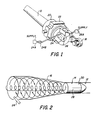
- FIGS 1 and 2 A liquid propellant gun embodying the HDSC is shown in FIGS 1 and 2.
- the gun includes a gun barrel (or tube) 10 having a forward firing bore 12, an intermediate, projectile receiving chamber 14, and an aft combustion chamber 16.
- the combustion chamber 16 can be bulbous shape having substantially aftmost diameter which is larger than the diameter of the projectile receiving chamber 14, and reduces forwardly progressively to the diameter of the projectile receiving chamber.
- the aft end of the combustion chamber is closed by a conventional breech mechanism 18.
- the gun barrel is mounted in a recoil cylinder 20.
- the recoil cylinder is supported by a conventional mount mechanism 22.
- a first chordal inlet 24 leads into the forward portion of the combustion chamber to provide a flow of liquid propellant on a tangent to the inner wall of the combustion chamber.
- the inlet 24 is fed by a supply 24A of liquid propellant under pressure through a valve 24B.
- This valve may be embodied as a powered metering cylinder.
- a second chordal inlet 26, serving as an ignitor, leads into the aft portion of the combustion chamber to provide a flow of ignition gas on a tangent to the inner wall of the combustion chamber.
- the radial position of the igniter is dependent on the application and the fraction of the charge that is desirable to have involved in the early portion of the ballistic cycle.
- the inlet 26 is fed by a supply 26A of high temperature combustion gas, e.g., such as in US Patent 4,231,282, issued November 4, 1980 to E. Ashley.
- a conventional projectile 28 is loaded into the chamber 14 and halted by the conventional forcing cone 30 transition in diameter between the bore 12 and the chamber 14.
- FIG. 2 A schematic of the fluid flow is shown in FIG. 2.
- the combustion chamber 16 is initially tangentially filled for the dynamic fill option by the inlet 24 from the supply 24A to approximately 70% loading by volume with liquid propellant, leaving an initial gas ullage of 30%.
- the fill system injects liquid propellant tangentially to develop a cyclonic flow pattern which centrifuges the liquid propellant about the longitudinal axis of the gun and causes the entrained ullage gas to migrate toward the longitudinal axis.
- an interface between the gas and the liquid exists even before the igniter gases enter the system.
- the igniter is also fired tangentially, by the inlet 26 from the supply 26A, into the combustion chamber near the breech, causing ignition gas to circulate circumferentially in the breech end of the combustion chamber and contribute to the cyclonic motion in the propellant.
- This causes a mixture of entrained fuel combustion by-product gas and igniter by-product gas and ignition gas to pass the igniter inlet 26 several times which promotes ignition.
- Ignition of the liquid propellant occurs at the breech end when the igniter induced chamber pressure reaches about 3000 psi; projectile motion forwardly past the forcing cone begins at about 5000 psi.
- the combustion gas will follow the projectile thereby causing liquid-gas surface area augmentation (by shear-generated instability) and the required increase in burn rate.
- the accelerating fluid field will form a burning region similar to a Taylor cavity which will penetrate to the base of the projectile. After this penetration by the Taylor cavity has occurred, Kelvin-Helmholtz instability on the remaining annulus of liquid propellant will augment the burning surface area until the charge is consumed. Depending on the loading density and fill process, the Helmholtz augmented burning may be established directly without Taylor cavity penetration.
- the critical phases of the HDSC ballistic cycle include (i) propellant fill, (ii) ignition, and (iii) combustion. Each of these phases is discussed in more detail below:
- Propellant Fill Two design criteria relevant to the HDSC are maintenance of a large ullage at fill (approximately 30% by volume at standard temperature and pressure) and arrangement of propellant injection to induce a cyclonic flow pattern in the chamber.
- the propellant mass 32 will retain its angular momentum for many seconds after the fill procedure has been completed.
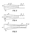
- FIG 3 shows the system containing a liquid annulus after fill.
- the fill orifice and the powered metering cylinder are adjusted to complete fill in less than one second. If more off a traveling charge effect is desired, a complete volumetric fill of the region nearer the projectile is preferred.
- the ignition process begins when hot gases 34 from the external igniter 26A are tangentially injected by inlet 26 at the breech end of the combustion chamber 16.
- An essential part of the HDSC ignition is the increased residence time of the liquid propellant in the vicinity of the ignition source 26, which is due to the swirling of the circumferentially injected igniter gases. Since the momentum of the igniter jet of gases is confined to a planar region in the breech, perpendicular to the gun axis, the gases must change direction as the pressure rises before an axial momentum component can be established in the gas flow. In the interim, the igniter jet will entrain some of the propellant in the re-circulation zone. (The parameters, which determine the magnitude of the fraction of the charge which will mix with the igniter gases, include igniter area, velocity, duration and breech configuration.)
- the propellant is more easily ignited as water vapor begins to be driven off at approximately 100°C.
- the propellant begins to "fizz" burn at approximately 124°C.
- This fizz mode consists of bond breaking and gasification of only the HAN component of the propellant.
- the gasification of HAN does not increase the chamber pressure significantly; the pressure rise is due principally to the igniter gases.
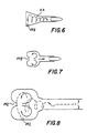
- the baseline shown in FIG 6, is identical to that shown in FIG 2, is the cyclonic or swirl, utilizes a tangential igniter 26A that promotes flow about the central axis and develops a gas cone.
- the second shown in FIG 7, utilizes a central igniter 26B that causes a toroidal circulation that will tend to propel heavy droplets down the combustion chamber forward portion.
- the third shown in FIG 8, utilizes a combination of the first two flow patterns with ignitors 26C and 26D plus a frictional hydrodynamic boundary layer to retard the flow at the walls of the combustion chamber forward portion and permits a central core, initially of propellant and later of gas, to flow rapidly forward with the base of the projectile to create the desired coupling with the combustion process.
- the housing 50 includes a gun barrel 52, a firing bore 54, a forcing cone 56, a projectile receiving portion 58, a combustion chamber 60 and a breech closure 62.
- a piston 64 is disposed within the chamber 60 and biases forwardly a weak spring 66 with a damper (dash-pot) 68.
- An igniter inlet 70 leads into the combustion chamber forward of the piston 64 at its forwardmost travel.
- a projectile 72 is inserted into the portion 58 until it lodges against the forcing cone 56. With the piston forward, the combustion chamber is fully loaded with propellant from inlet 74 just aft of the base of the projectile.
- the igniter gas flow will first push the piston back against the weak spring while the swirl is being established. Only after the piston bottoms will the propellant be pressurized significantly. Thus when the propellant is ignited, all of the liquid propellant is in the forward portion of the combustion chamber and the igniter gas has displaced the piston to enlarge the volume of the combustion chamber to provide a loading density which is significantly less than 100%. If the displacement volume provided by the piston is 30% of the final volume of the chamber, the loading density is 70%.
- This approach has the additional advantage of pre-positioning the propellant immediately aft of the projectile in a favorable configuration for a traveling charge effect wherein the remainder of the liquid charge moves forwardly with the projectile.
- FIG 10 shows another approach to achieve the same ballistic functions.
- the housing 80 includes a gun barrel portion 82, a firing bore 84, a forcing cone 86, a forward combustion chamber 88 and an aft combustion chamber 90.
- a piston valve 92 has a truncated conical head portion 94 having a forward circular face 96 and an aft annular face 98, and a base portion 100 having a forward annular face 102.
- a spring 104 biases the piston forwardly so that the piston head 94 closes off the forward chamber 88 from the aft chamber 90.
- the face 96 has the largest area, the face 98 has less area, and the face 102 has the least area.
- a chordal inlet 104 for liquid propellant is provided in the forward chamber, aft of the base of the projectile 106 which is positioned in the bore 84 by the forcing cone 86.
- a chordal inlet 112 for liquid propellant is provided in the aft chamber.
- a pressurized supply 114 of liquid propellant, via a valve 116 provides a small charge of liquid propellant, leaving a large ullage volume, in the aft chamber.
- a chordal inlet 118 for ignition gas is provided in the aft part of the aft chamber and is coupled to a source of ignition gas 120 through a valve 122.
- the forward chamber When ignition gas is initially supplied into the aft chamber, the forward chamber is sealed off by the piston head 94 and the ignition gas recirculates in the high ullage, low propellant density volume. As pressure builds up, the pressure differential between the forward face 98 and the aft face 102 overcomes the bias of the spring to move the piston aftwardly. An annular opening 126 is thus provided for the combustion gas into the column of propellant in the forward chamber.
Landscapes
- Engineering & Computer Science (AREA)
- Chemical & Material Sciences (AREA)
- Combustion & Propulsion (AREA)
- General Engineering & Computer Science (AREA)
- Feeding, Discharge, Calcimining, Fusing, And Gas-Generation Devices (AREA)
- Fuel-Injection Apparatus (AREA)
- Air Bags (AREA)
- Combustion Methods Of Internal-Combustion Engines (AREA)
- Filling Or Discharging Of Gas Storage Vessels (AREA)
Applications Claiming Priority (2)
| Application Number | Priority Date | Filing Date | Title |
|---|---|---|---|
| US07/456,417 US5016517A (en) | 1989-12-26 | 1989-12-26 | Liquid propellant gun |
| US456417 | 1989-12-26 |
Publications (2)
| Publication Number | Publication Date |
|---|---|
| EP0436329A1 true EP0436329A1 (de) | 1991-07-10 |
| EP0436329B1 EP0436329B1 (de) | 1996-07-24 |
Family
ID=23812676
Family Applications (1)
| Application Number | Title | Priority Date | Filing Date |
|---|---|---|---|
| EP90313623A Expired - Lifetime EP0436329B1 (de) | 1989-12-26 | 1990-12-14 | Kanone mit flüssigem Treibmittel |
Country Status (7)
| Country | Link |
|---|---|
| US (1) | US5016517A (de) |
| EP (1) | EP0436329B1 (de) |
| JP (1) | JPH03217796A (de) |
| KR (1) | KR0174738B1 (de) |
| CA (1) | CA2029166A1 (de) |
| DE (1) | DE69027920T2 (de) |
| IL (1) | IL96701A (de) |
Families Citing this family (1)
| Publication number | Priority date | Publication date | Assignee | Title |
|---|---|---|---|---|
| US5232526A (en) * | 1992-07-10 | 1993-08-03 | Thiokol Corporation | Diethanolammoniummethylcubane nitrates hydroxylammonium nitrate (HAN) solutions as aqueous liquid gun propellant ingredients |
Citations (5)
| Publication number | Priority date | Publication date | Assignee | Title |
|---|---|---|---|---|
| CH399252A (fr) * | 1963-06-13 | 1966-03-31 | Pellaux Roger | Arme à feu automatique |
| US4099445A (en) * | 1968-08-21 | 1978-07-11 | Messerschmitt-Bolkow-Blohm Gmbh | Pressure differential piston-combustion chamber system |
| US4281582A (en) * | 1979-06-19 | 1981-08-04 | The United States Of America As Represented By The Secretary Of The Air Force | Control piston for liquid propellant gun injector |
| GB1605165A (en) * | 1972-04-13 | 1982-09-08 | Rheinmetall Gmbh | Arrangement for firing a round of amunition by means of a liquid propellant |
| DE2518149C1 (de) * | 1975-04-24 | 1985-10-31 | Messerschmitt-Bölkow-Blohm GmbH, 8000 München | Treibgaserzeugungssystem,insbesondere fuer Schusswaffen |
Family Cites Families (7)
| Publication number | Priority date | Publication date | Assignee | Title |
|---|---|---|---|---|
| US3426534A (en) * | 1966-06-02 | 1969-02-11 | Thiokol Chemical Corp | Fuel control device |
| US4023463A (en) * | 1976-06-10 | 1977-05-17 | General Electric Company | Liquid propellant gun (check valve and damper) |
| US4160405A (en) * | 1978-02-21 | 1979-07-10 | The United States Of America As Represented By The Secretary Of The Navy | Liquid propellant gun, positive displacement single valve |
| US4269107A (en) * | 1979-06-19 | 1981-05-26 | The United States Of America As Represented By The Secretary Of The Air Force | Liquid propellant/regenerative charging system bubble preventer |
| US4478128A (en) * | 1981-05-11 | 1984-10-23 | The United States Of America As Represented By The Secretary Of The Navy | Projectile carrier for liquid propellant gun |
| US4523508A (en) * | 1983-11-02 | 1985-06-18 | General Electric Company | In-line annular piston fixed bolt regenerative liquid propellant gun |
| US4586422A (en) * | 1984-04-10 | 1986-05-06 | General Electric Company | In-line annular piston fixed bolt regenerative variable charge liquid propellant gun with variable hydraulic control of piston |
-
1989
- 1989-12-26 US US07/456,417 patent/US5016517A/en not_active Expired - Fee Related
-
1990
- 1990-11-01 CA CA002029166A patent/CA2029166A1/en not_active Abandoned
- 1990-11-29 JP JP2333400A patent/JPH03217796A/ja active Pending
- 1990-12-14 EP EP90313623A patent/EP0436329B1/de not_active Expired - Lifetime
- 1990-12-14 DE DE69027920T patent/DE69027920T2/de not_active Expired - Fee Related
- 1990-12-17 IL IL9670190A patent/IL96701A/en not_active IP Right Cessation
- 1990-12-24 KR KR1019900021743A patent/KR0174738B1/ko not_active IP Right Cessation
Patent Citations (5)
| Publication number | Priority date | Publication date | Assignee | Title |
|---|---|---|---|---|
| CH399252A (fr) * | 1963-06-13 | 1966-03-31 | Pellaux Roger | Arme à feu automatique |
| US4099445A (en) * | 1968-08-21 | 1978-07-11 | Messerschmitt-Bolkow-Blohm Gmbh | Pressure differential piston-combustion chamber system |
| GB1605165A (en) * | 1972-04-13 | 1982-09-08 | Rheinmetall Gmbh | Arrangement for firing a round of amunition by means of a liquid propellant |
| DE2518149C1 (de) * | 1975-04-24 | 1985-10-31 | Messerschmitt-Bölkow-Blohm GmbH, 8000 München | Treibgaserzeugungssystem,insbesondere fuer Schusswaffen |
| US4281582A (en) * | 1979-06-19 | 1981-08-04 | The United States Of America As Represented By The Secretary Of The Air Force | Control piston for liquid propellant gun injector |
Also Published As
| Publication number | Publication date |
|---|---|
| IL96701A (en) | 1996-12-05 |
| KR0174738B1 (ko) | 1999-02-18 |
| EP0436329B1 (de) | 1996-07-24 |
| DE69027920D1 (de) | 1996-08-29 |
| KR910012645A (ko) | 1991-08-08 |
| CA2029166A1 (en) | 1991-06-27 |
| JPH03217796A (ja) | 1991-09-25 |
| IL96701A0 (en) | 1991-09-16 |
| US5016517A (en) | 1991-05-21 |
| DE69027920T2 (de) | 1997-02-27 |
Similar Documents
| Publication | Publication Date | Title |
|---|---|---|
| US4726279A (en) | Wake stabilized supersonic combustion ram cannon | |
| CA1290178C (en) | Armament system | |
| US3011404A (en) | Liquid propellant squeeze-bore gun with deformable projectile sabot | |
| US5873240A (en) | Pulsed detonation rocket engine | |
| US5233903A (en) | Gun with combined operation by chemical propellant and plasma | |
| US5079987A (en) | Liquid propellant gun | |
| US4132149A (en) | Liquid propellant weapon system | |
| US4726184A (en) | Rocket engine assembly | |
| US4126078A (en) | Liquid propellant weapon system | |
| EP0436329B1 (de) | Kanone mit flüssigem Treibmittel | |
| EP0321102B1 (de) | Geschütz für Flüssigkeitstreibmittel | |
| US4011817A (en) | Liquid propellant weapon system | |
| US4949621A (en) | Liquid propellant gun | |
| US4397240A (en) | Rocket assisted projectile and cartridge with time delay ignition and sealing arrangement | |
| US4051762A (en) | Liquid propellant weapon system | |
| US4722185A (en) | Double piston rocket engine assembly | |
| CA1310213C (en) | Liquid propellant weapon system | |
| US4852458A (en) | Liquid propellant weapon system | |
| EP0382000B1 (de) | Mit einer Kombination von Plasmaantrieb und chemischer Treibladung arbeitendes Geschütz | |
| US4930423A (en) | Liquid propellant weapon system | |
| RU2812284C1 (ru) | Способ производства выстрела из баллистической установки с использованием кумулятивного и гидродинамического эффекта | |
| Seiler et al. | Influence of projectile material and gas composition on superdetonative combustion in ISL's RAMAC 30 | |
| KR960016046B1 (ko) | 액체 추진제 무기 시스템 | |
| US4993309A (en) | Liquid propellant weapon system | |
| CA1333669C (en) | Liquid propellant weapon system |
Legal Events
| Date | Code | Title | Description |
|---|---|---|---|
| PUAI | Public reference made under article 153(3) epc to a published international application that has entered the european phase |
Free format text: ORIGINAL CODE: 0009012 |
|
| AK | Designated contracting states |
Kind code of ref document: A1 Designated state(s): BE CH DE FR GB IT LI SE |
|
| 17P | Request for examination filed |
Effective date: 19911216 |
|
| 17Q | First examination report despatched |
Effective date: 19930805 |
|
| GRAH | Despatch of communication of intention to grant a patent |
Free format text: ORIGINAL CODE: EPIDOS IGRA |
|
| GRAH | Despatch of communication of intention to grant a patent |
Free format text: ORIGINAL CODE: EPIDOS IGRA |
|
| GRAA | (expected) grant |
Free format text: ORIGINAL CODE: 0009210 |
|
| AK | Designated contracting states |
Kind code of ref document: B1 Designated state(s): BE CH DE FR GB IT LI SE |
|
| PG25 | Lapsed in a contracting state [announced via postgrant information from national office to epo] |
Ref country code: IT Free format text: LAPSE BECAUSE OF FAILURE TO SUBMIT A TRANSLATION OF THE DESCRIPTION OR TO PAY THE FEE WITHIN THE PRESCRIBED TIME-LIMIT;WARNING: LAPSES OF ITALIAN PATENTS WITH EFFECTIVE DATE BEFORE 2007 MAY HAVE OCCURRED AT ANY TIME BEFORE 2007. THE CORRECT EFFECTIVE DATE MAY BE DIFFERENT FROM THE ONE RECORDED. Effective date: 19960724 Ref country code: LI Effective date: 19960724 Ref country code: BE Effective date: 19960724 Ref country code: CH Effective date: 19960724 |
|
| ET | Fr: translation filed | ||
| REF | Corresponds to: |
Ref document number: 69027920 Country of ref document: DE Date of ref document: 19960829 |
|
| PG25 | Lapsed in a contracting state [announced via postgrant information from national office to epo] |
Ref country code: SE Effective date: 19961024 |
|
| PGFP | Annual fee paid to national office [announced via postgrant information from national office to epo] |
Ref country code: FR Payment date: 19961115 Year of fee payment: 7 |
|
| PGFP | Annual fee paid to national office [announced via postgrant information from national office to epo] |
Ref country code: DE Payment date: 19961122 Year of fee payment: 7 |
|
| PGFP | Annual fee paid to national office [announced via postgrant information from national office to epo] |
Ref country code: GB Payment date: 19961128 Year of fee payment: 7 |
|
| REG | Reference to a national code |
Ref country code: CH Ref legal event code: PL |
|
| PLBE | No opposition filed within time limit |
Free format text: ORIGINAL CODE: 0009261 |
|
| STAA | Information on the status of an ep patent application or granted ep patent |
Free format text: STATUS: NO OPPOSITION FILED WITHIN TIME LIMIT |
|
| 26N | No opposition filed | ||
| PG25 | Lapsed in a contracting state [announced via postgrant information from national office to epo] |
Ref country code: GB Free format text: LAPSE BECAUSE OF NON-PAYMENT OF DUE FEES Effective date: 19971214 |
|
| PG25 | Lapsed in a contracting state [announced via postgrant information from national office to epo] |
Ref country code: FR Free format text: THE PATENT HAS BEEN ANNULLED BY A DECISION OF A NATIONAL AUTHORITY Effective date: 19971231 |
|
| GBPC | Gb: european patent ceased through non-payment of renewal fee |
Effective date: 19971214 |
|
| PG25 | Lapsed in a contracting state [announced via postgrant information from national office to epo] |
Ref country code: DE Free format text: LAPSE BECAUSE OF NON-PAYMENT OF DUE FEES Effective date: 19980901 |
|
| REG | Reference to a national code |
Ref country code: FR Ref legal event code: ST |