EP0436313B1 - Circular knitting machine - Google Patents
Circular knitting machine Download PDFInfo
- Publication number
- EP0436313B1 EP0436313B1 EP90313333A EP90313333A EP0436313B1 EP 0436313 B1 EP0436313 B1 EP 0436313B1 EP 90313333 A EP90313333 A EP 90313333A EP 90313333 A EP90313333 A EP 90313333A EP 0436313 B1 EP0436313 B1 EP 0436313B1
- Authority
- EP
- European Patent Office
- Prior art keywords
- dial
- needle
- knitting machine
- support shaft
- needle cylinder
- Prior art date
- Legal status (The legal status is an assumption and is not a legal conclusion. Google has not performed a legal analysis and makes no representation as to the accuracy of the status listed.)
- Expired - Lifetime
Links
Images

Classifications
-
- D—TEXTILES; PAPER
- D04—BRAIDING; LACE-MAKING; KNITTING; TRIMMINGS; NON-WOVEN FABRICS
- D04B—KNITTING
- D04B9/00—Circular knitting machines with independently-movable needles
-
- D—TEXTILES; PAPER
- D04—BRAIDING; LACE-MAKING; KNITTING; TRIMMINGS; NON-WOVEN FABRICS
- D04B—KNITTING
- D04B15/00—Details of, or auxiliary devices incorporated in, weft knitting machines, restricted to machines of this kind
- D04B15/94—Driving-gear not otherwise provided for
-
- D—TEXTILES; PAPER
- D04—BRAIDING; LACE-MAKING; KNITTING; TRIMMINGS; NON-WOVEN FABRICS
- D04B—KNITTING
- D04B15/00—Details of, or auxiliary devices incorporated in, weft knitting machines, restricted to machines of this kind
- D04B15/14—Needle cylinders
-
- D—TEXTILES; PAPER
- D04—BRAIDING; LACE-MAKING; KNITTING; TRIMMINGS; NON-WOVEN FABRICS
- D04B—KNITTING
- D04B15/00—Details of, or auxiliary devices incorporated in, weft knitting machines, restricted to machines of this kind
- D04B15/18—Dials
-
- D—TEXTILES; PAPER
- D04—BRAIDING; LACE-MAKING; KNITTING; TRIMMINGS; NON-WOVEN FABRICS
- D04B—KNITTING
- D04B9/00—Circular knitting machines with independently-movable needles
- D04B9/06—Circular knitting machines with independently-movable needles with needle cylinder and dial for ribbed goods
Definitions
- This invention relates to circular knitting machines and in particular to a double knit circular knitting machine having a dial which can be lifted a sufficient distance for facilitating removal and replacement of the needle cylinder and needle dial.
- This known type of knitting machine includes a circular dial supported adjacent an opening in the upper end of the needle cylinder and a rotatable support shaft supported at its upper end on a frame support member and extending downwardly to a position adjacent the circular opening in the upper end of the needle cylinder.
- a vertically extending support sleeve surrounds the support shaft and is supported at the upper end on the frame support member for vertical movement. The lower end of the support sleeve is fixed to the dial for supporting same.
- a dial control is provided for lifting and lowering the support sleeve along the support shaft to lift the dial and its associated dial cam holder.
- the dial It has been found desirable to mount the dial so that the needle cylinder can be more easily removed through the formed space above the needle cylinder. Additionally, after removal and replacement of component parts, the dial must be set to exact specifications. Thus, it is desirable to form the dial so that it may not only be more easily removed, but also readily inserted and positioned in an exact and properly adjusted position.
- a knitting machine comprising a frame, a needle cylinder, releasably mounted upon said frame for rotative movement relative to said frame during operation of said machine, a generally vertical support shaft carried by said frame, a needle dial releasably secured to said support shaft, a support sleeve encircling said support shaft, a dial cam holder carried by said support sleeve, control means for lifting and lowering said support sleeve wherby said dial cam holder and said needle dial are vertically moved so as to provide vertical clearance between said needle dial and said needle cylinder, characterised in that said support shaft has a circular stepped portion at its lower end, said needle dial has an opening closely receiving said stepped portion of said support shaft and a support shaft engaging upper surface and an upper dial cam holder engaging surface that are flush with each other, and said vertical clearance is sufficient to permit lateral movement of said needle cylinder into and from said knitting machine.
- the knitting machine includes a frame and a bed plate fixed on the frame.
- a needle cylinder is supported for rotation on the bed plate and includes needles supported for vertical movement therewithin.
- the needle cylinder has a circular opening at the upper end.
- a frame support member extends in spaced relationship above the upper end of the needle cylinder.
- a vertically extending rotatable support shaft is supported at the upper end on the frame support member and extends downward to a position adjacent the opening in the upper end of the needle cylinder.
- the shaft has a diametral stepped lower end portion.
- the needle dial is supported adjacent the opening in the upper end of the needle cylinder.
- the dial has a shaft engaging upper surface and an upper dial cam holder engaging surface lying substantially flush with each other.
- the needle dial opening is dimensioned substantially equal to the stepped portion on the support shaft for receiving the stepped portion of the shaft therethrough to aid in positioning same thereat.
- Vertically extending support sleeve means surrounds the support shaft and is supported at the upper end on the frame support member for vertical movement. The lower end of the support sleeve is fixed to the dial cam holder for supporting same.
- Dial control means lifts and lowers the support sleeve means to thereby lift and lower the dial cam holder fixed to the support sleeve. Dial control means is operable to lift the dial a sufficient distance to permit removal and replacement of the needle cylinder.
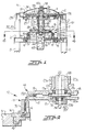
- a bed plate 1 is supported on the upper ends of preferably three equally spaced support legs 2 and 3 only two of which are illustrated.
- a knitting unit, broadly indicated at 12, is affixed on the bed plate 1 and operates to knit tubular fabric which typically is wound flattened onto a roll or other take-up apparatus (not shown) positioned below the knitting unit 12.
- a first large, annular driven gear 4 is rotatably held in the bed plate 1.
- the needle cylinder 6 is positioned on the upper side of the driven gear 4 and rests on a replaceable intermediate rest 5 positioned between the driven gear 4 and bed plate 1.
- the provision of the intermediate rest 5 between the driven gear 4 and the bed plate 1 facilitates replacement of the needle cylinder 6.
- several component parts, including the first large driven gear and an intermediate gear are replaced when the needle cylinder 6 is changed.
- the needle cylinder 6 and intermediate rest 5 only have to be changed when changing the needle cylinder 6 for a cylinder of different diameter.
- the large driven gear 4 meshes with a driving gear 8 secured on the knitting machine drive shaft 7.
- a power source (not shown) conventionally positioned in the knitting machine, provides the necessary force for rotating the drive shaft 7.
- a second driven gear 10 is positioned at the top of the drive shaft 7 and meshes with a second large annular gear 9.
- the drive shaft 7 is covered with a cylindrical protective member 11 for protection of the shaft against contaminants and other harmful effects.
- the knitting unit 12 includes a cylinder needle area 13, dial needle area 14, and the usual yarn carriers (not shown).
- the cylinder needle area 13 includes a plurality of needle groves formed in the outer periphery of the needle cylinder 6 and includes a circular opening at the upper end thereof.
- Cylinder needles (not shown) are mounted for vertical sliding movement along the formed grooves.
- Needle activating cams are mounted on the inner surface of a cam holder 15 for controlling movement of the needle cylinder 6 during knitting.
- the cam holder 15 is supported on the upper part of a circular cam ring 16 which is fixed to the bed plate 1.
- the dial needle area 14 includes dial element means including a dial 17 having dial grooves therein.
- Dial needles (not shown) are mounted in the dial grooves for radially sliding along the formed dial grooves.
- Dial needle activating cams are supported on the lower surface of a dial cam holder 18 and control movement of the dial needles.
- the needle cylinder 6 and dial 17 are rotated at the same speed.
- the dial 17 is fixed to the planar underside surface of a diametrically enlarged, portion 20a of a hollow support shaft 20 by bolts 21.
- the dial 17 includes a shaft engaging upper surface 17a which engages the lower end of the stepped portion 20b on the lower end of the support shaft 20 and a dial cam holder engaging surface 17b.
- the surface 17a of the needle dial 17 which engages the lower portion of the support shaft 20 is constructed flush with the upper dial cam holder engaging surface 17b defining the upper surface. Precise positioning of the needle dial 17 occurs when the dial 17 is fixed to the support shaft 20.
- the needle dial aperture is approximately equal to that of the diametrically small stepped portion of the support shaft 20.
- the size of the small stepped portion 20b of the support shaft 20 is about 10 mm regardless of nominal size.
- the support shaft 20 is rotatably supported by upper and lower bearing assemblies 22 and 23 which are held on upper and lower portions of vertically extending support sleeve means in the form of a cylinder support sleeve member 19b which surrounds the support shaft 20.
- the second large gear 9 is fixed at the upper end of the support shaft 20 by a lock nut 25 having a key 24 extending therethrough.
- the upper end of the support sleeve 19b member is supported for vertical movement relative to the frame support member 27.
- the lower end of the support sleeve member 19a is fixed to the dial cam holder 18.
- the support sleeve member 19b is vertically slidable in an outer cylinder 27a extending downwardly from a frame support member 27.
- the frame support member 27 is diametrically enlarged at an upper portion and is fixed to an outer cylinder support frame 28.
- the outer cylinder support frame 28 is held by three supports 31, 32 and 33 engaging the bed plate 1, only two of which are shown in Figure 1.
- Dial control means 29, 26 with a retainer 26a for preventing vertical movement is provided for lifting and lowering the support sleeve member 19b. Such movement lifts and lowers the dial 17 fixed to the support shaft 20 and the dial cam holder 18 fixed to the support sleeve member 19b, so as to lift the dial 17 a sufficient distance to permit removal and replacement of the needle cylinder 6.
- the dial control means includes a driving gear 29 which meshes with a gear 26 and a vertical shaft 30 supported by the frame support member 27.
- the gear 26 is supported on the upper end of the support sleeve member 19b and operates to raise and lower the support sleeve member.
- Power air introducing means indicated generally as 35 is provided for introducing air into the support shaft 20.
- the support shaft 20 is hollow and includes a hollow formed portion 20c ( Figure 2) in which air can be forced therethrough.
- the power air introducing means 35 comprises a stationary vertical shaft 36, an upper housing 37 for containing electrical terminals, a bearing assembly 38 positioned at an air introducing-end port, and a lower bearing housing 39 having an air introducing-out port.
- the shaft 36 is supported at its upper end by the bearing assembly 38.
- the bearing assembly 38 is fixed to a cover 34.
- the lower bearing housing 39 includes a bearing 40.
- the upper housing 37 contains an electrical terminal member 42 which is biased by a spring 41.
- the electrical terminal member 42 communicates with the top of the stationary vertical shaft 36.
- a lamp 43 and transformer 44 are positioned in the lower portion of the stationary vertical shaft 36.
- the transformer 44 is fixed to the stationary vertical shaft 36.
- the bearing housing 39 rotates around the stationary vertical shaft 36.
- Catching number 45, ( Figure 3) prevents the vertical shaft 36 from rotating.
- the needle dial 17 When the gauge or nominal size of the knitting machine is to be changed, the needle dial 17 is raised upward for allowing clearance to remove the needle cylinder. This is accomplished by turning the vertical shaft 30 by means of a tool, such as a hexagonal wrench. As the vertical shaft 30 is turned, it rotatively drives the cylinder gear 26 meshing with the driving gear 29. As the gears turn, needle dial 17 is moved upward about 10 mm and a space is provided above the needle cylinder 6.
- the present invention offers several benefits over other prior art apparatus. Not only is the needle cylinder 6 and needle dial 17 removed without the need of using chain block, but the needle dial 17 can be reset with little difficulty. Because both the shaft engaging upper surface 17a and upper dial cam holder engaging surface 17b are substantially flush with each other, removal of the needle cylinder 6 is facilitated. Additionally, the needle dial 17 is positioned readily without difficulty during reassembly because the needle dial orifice is dimensioned substantially equal to the stepped portion of the support shaft 20 for receiving the stepped portion of the shaft 20 therethrough to aid in positioning the needle dial 17.
Landscapes
- Engineering & Computer Science (AREA)
- Textile Engineering (AREA)
- Knitting Machines (AREA)
Description
- This invention relates to circular knitting machines and in particular to a double knit circular knitting machine having a dial which can be lifted a sufficient distance for facilitating removal and replacement of the needle cylinder and needle dial.
- It is generally known to construct a double knit circular knitting machine in such a manner to facilitate replacement of the needle cylinder and sinker dial. This known type of knitting machine includes a circular dial supported adjacent an opening in the upper end of the needle cylinder and a rotatable support shaft supported at its upper end on a frame support member and extending downwardly to a position adjacent the circular opening in the upper end of the needle cylinder. A vertically extending support sleeve surrounds the support shaft and is supported at the upper end on the frame support member for vertical movement. The lower end of the support sleeve is fixed to the dial for supporting same. A dial control is provided for lifting and lowering the support sleeve along the support shaft to lift the dial and its associated dial cam holder. Such knitting machines are described in patent specifications EP-A-0 413 608 and GB 1256196 in which a circular needle dial has a downwardly facing support shaft engaging face and an upwardly facing dial cam holder engaging surface. The needle dial is urged downwardly onto a flange projecting from a lower region of the support shaft. (EP-A-0 413 608 has a priority date of 18 August 1989 and was published on 20 February 1991). In the case of the knitting machine in EP-A-0 413 608 the dial can be lifted a sufficient distance to permit removal and replacement of the needle cylinder.
- It has been found desirable to mount the dial so that the needle cylinder can be more easily removed through the formed space above the needle cylinder. Additionally, after removal and replacement of component parts, the dial must be set to exact specifications. Thus, it is desirable to form the dial so that it may not only be more easily removed, but also readily inserted and positioned in an exact and properly adjusted position.
- It is therefore an object of this invention to provide a circular knitting machine which is constructed to facilitate more ready replacement of the needle cylinder and wherein the needle dial can be replaced and reset more exactly than heretofore accomplished.
- Thus, according to the present invention there is provided a knitting machine comprising a frame, a needle cylinder, releasably mounted upon said frame for rotative movement relative to said frame during operation of said machine, a generally vertical support shaft carried by said frame, a needle dial releasably secured to said support shaft, a support sleeve encircling said support shaft, a dial cam holder carried by said support sleeve, control means for lifting and lowering said support sleeve wherby said dial cam holder and said needle dial are vertically moved so as to provide vertical clearance between said needle dial and said needle cylinder, characterised in that said support shaft has a circular stepped portion at its lower end, said needle dial has an opening closely receiving said stepped portion of said support shaft and a support shaft engaging upper surface and an upper dial cam holder engaging surface that are flush with each other, and said vertical clearance is sufficient to permit lateral movement of said needle cylinder into and from said knitting machine.
- The knitting machine includes a frame and a bed plate fixed on the frame. A needle cylinder is supported for rotation on the bed plate and includes needles supported for vertical movement therewithin. The needle cylinder has a circular opening at the upper end. A frame support member extends in spaced relationship above the upper end of the needle cylinder. A vertically extending rotatable support shaft is supported at the upper end on the frame support member and extends downward to a position adjacent the opening in the upper end of the needle cylinder. The shaft has a diametral stepped lower end portion.
- The needle dial is supported adjacent the opening in the upper end of the needle cylinder. The dial has a shaft engaging upper surface and an upper dial cam holder engaging surface lying substantially flush with each other. The needle dial opening is dimensioned substantially equal to the stepped portion on the support shaft for receiving the stepped portion of the shaft therethrough to aid in positioning same thereat.
- Vertically extending support sleeve means surrounds the support shaft and is supported at the upper end on the frame support member for vertical movement. The lower end of the support sleeve is fixed to the dial cam holder for supporting same. Dial control means lifts and lowers the support sleeve means to thereby lift and lower the dial cam holder fixed to the support sleeve. Dial control means is operable to lift the dial a sufficient distance to permit removal and replacement of the needle cylinder.
- Sliding removal of the needle dial is facilitated because the shaft engaging upper surface and upper dial cam holder engaging surface lie substantially in the same plane, i.e. flush with each other. Additionally, resetting of the needle dial is facilitated because the needle dial aperture is dimensioned substantially equal to the stepped portion of the shaft to aid in positioning the needle dial thereat.
- In order that the present invention may be more readily understood, reference will now be made to the accompanying drawings, in which:-
- Figure 1 is a front, somewhat schematic vertical sectional view of the upper portion of a knitting machine in accordance with the present invention;
- Figure 2 is an enlarged sectional view of component members of the needle cylinder and needle dial;
- Figure 3 is an enlarged somewhat schematic sectional view of the pneumatic air control means which detachably secures to the support shaft; and
- Figure 4 is a horizontal sectional view taken along the line 4-4 in Figure 1 and showing the direction of removal of the needle cylinder and dial laterally therefrom.
- Referring now to the drawings, and more particularly to Figure 1, there is illustrated a double knit circular knitting machine in accordance with a preferred embodiment of the present invention. A
bed plate 1 is supported on the upper ends of preferably three equallyspaced support legs 2 and 3 only two of which are illustrated. A knitting unit, broadly indicated at 12, is affixed on thebed plate 1 and operates to knit tubular fabric which typically is wound flattened onto a roll or other take-up apparatus (not shown) positioned below theknitting unit 12. - A first large, annular driven
gear 4 is rotatably held in thebed plate 1. Theneedle cylinder 6 is positioned on the upper side of the drivengear 4 and rests on a replaceableintermediate rest 5 positioned between the drivengear 4 andbed plate 1. The provision of theintermediate rest 5 between the drivengear 4 and thebed plate 1 facilitates replacement of theneedle cylinder 6. In more conventional knitting machines, several component parts, including the first large driven gear and an intermediate gear are replaced when theneedle cylinder 6 is changed. In the structure of the present invention, theneedle cylinder 6 andintermediate rest 5 only have to be changed when changing theneedle cylinder 6 for a cylinder of different diameter. In the present invention the large drivengear 4 meshes with a driving gear 8 secured on the knitting machine drive shaft 7. A power source (not shown) conventionally positioned in the knitting machine, provides the necessary force for rotating the drive shaft 7. A second drivengear 10 is positioned at the top of the drive shaft 7 and meshes with a second large annular gear 9. The drive shaft 7 is covered with a cylindricalprotective member 11 for protection of the shaft against contaminants and other harmful effects. - As illustrated, the
knitting unit 12 includes acylinder needle area 13,dial needle area 14, and the usual yarn carriers (not shown). Thecylinder needle area 13 includes a plurality of needle groves formed in the outer periphery of theneedle cylinder 6 and includes a circular opening at the upper end thereof. Cylinder needles (not shown) are mounted for vertical sliding movement along the formed grooves. Needle activating cams are mounted on the inner surface of acam holder 15 for controlling movement of theneedle cylinder 6 during knitting. Thecam holder 15 is supported on the upper part of acircular cam ring 16 which is fixed to thebed plate 1. - The
dial needle area 14 includes dial element means including adial 17 having dial grooves therein. Dial needles (not shown) are mounted in the dial grooves for radially sliding along the formed dial grooves. Dial needle activating cams are supported on the lower surface of adial cam holder 18 and control movement of the dial needles. Theneedle cylinder 6 anddial 17 are rotated at the same speed. As illustrated in figure 2, thedial 17 is fixed to the planar underside surface of a diametrically enlarged,portion 20a of ahollow support shaft 20 bybolts 21. Thedial 17 includes a shaft engagingupper surface 17a which engages the lower end of the steppedportion 20b on the lower end of thesupport shaft 20 and a dial cam holder engaging surface 17b. Thesurface 17a of theneedle dial 17 which engages the lower portion of thesupport shaft 20 is constructed flush with the upper dial cam holder engaging surface 17b defining the upper surface. Precise positioning of theneedle dial 17 occurs when thedial 17 is fixed to thesupport shaft 20. The needle dial aperture is approximately equal to that of the diametrically small stepped portion of thesupport shaft 20. The size of the smallstepped portion 20b of thesupport shaft 20 is about 10 mm regardless of nominal size. - As illustrated in Figure 1, the
support shaft 20 is rotatably supported by upper andlower bearing assemblies support sleeve member 19b which surrounds thesupport shaft 20. The second large gear 9 is fixed at the upper end of thesupport shaft 20 by alock nut 25 having akey 24 extending therethrough. The upper end of thesupport sleeve 19b member is supported for vertical movement relative to theframe support member 27. The lower end of the support sleeve member 19a is fixed to thedial cam holder 18. - As illustrated, the
support sleeve member 19b is vertically slidable in anouter cylinder 27a extending downwardly from aframe support member 27. Theframe support member 27 is diametrically enlarged at an upper portion and is fixed to an outercylinder support frame 28. The outercylinder support frame 28 is held by threesupports bed plate 1, only two of which are shown in Figure 1. - Dial control means 29, 26 with a retainer 26a for preventing vertical movement is provided for lifting and lowering the
support sleeve member 19b. Such movement lifts and lowers thedial 17 fixed to thesupport shaft 20 and thedial cam holder 18 fixed to thesupport sleeve member 19b, so as to lift thedial 17 a sufficient distance to permit removal and replacement of theneedle cylinder 6. The dial control means includes adriving gear 29 which meshes with agear 26 and avertical shaft 30 supported by theframe support member 27. Thegear 26 is supported on the upper end of thesupport sleeve member 19b and operates to raise and lower the support sleeve member. - Power air introducing means indicated generally as 35 (Figure 3) is provided for introducing air into the
support shaft 20. As illustrated, thesupport shaft 20 is hollow and includes a hollow formedportion 20c (Figure 2) in which air can be forced therethrough. As illustrated in greater detail in figure 3, the powerair introducing means 35 comprises a stationaryvertical shaft 36, anupper housing 37 for containing electrical terminals, a bearingassembly 38 positioned at an air introducing-end port, and alower bearing housing 39 having an air introducing-out port. Theshaft 36 is supported at its upper end by the bearingassembly 38. The bearingassembly 38 is fixed to acover 34. Thelower bearing housing 39 includes abearing 40. Theupper housing 37 contains anelectrical terminal member 42 which is biased by aspring 41. Theelectrical terminal member 42 communicates with the top of the stationaryvertical shaft 36. As shown in figure 1, alamp 43 andtransformer 44 are positioned in the lower portion of the stationaryvertical shaft 36. Thetransformer 44 is fixed to the stationaryvertical shaft 36. As thedrive shaft 20 rotates, the bearinghousing 39 rotates around the stationaryvertical shaft 36. Catchingnumber 45, (Figure 3) prevents thevertical shaft 36 from rotating. - When the gauge or nominal size of the knitting machine is to be changed, the
needle dial 17 is raised upward for allowing clearance to remove the needle cylinder. This is accomplished by turning thevertical shaft 30 by means of a tool, such as a hexagonal wrench. As thevertical shaft 30 is turned, it rotatively drives thecylinder gear 26 meshing with thedriving gear 29. As the gears turn,needle dial 17 is moved upward about 10 mm and a space is provided above theneedle cylinder 6. - The
bolts 21 retaining theneedle dial 17 to thesupport shaft 20 then are removed, and theneedle dial 17 andneedle cylinder 6 are removed as one unit (Figure 4). Additionally, theair introduction assembly 35 is removed beforehand by loosening thenut 46 at the air introducing-out port and removing the assembly downward (Figure 3). - The present invention offers several benefits over other prior art apparatus. Not only is the
needle cylinder 6 andneedle dial 17 removed without the need of using chain block, but theneedle dial 17 can be reset with little difficulty. Because both the shaft engagingupper surface 17a and upper dial cam holder engaging surface 17b are substantially flush with each other, removal of theneedle cylinder 6 is facilitated. Additionally, theneedle dial 17 is positioned readily without difficulty during reassembly because the needle dial orifice is dimensioned substantially equal to the stepped portion of thesupport shaft 20 for receiving the stepped portion of theshaft 20 therethrough to aid in positioning theneedle dial 17.
Claims (7)
- A knitting machine comprising:
a frame (1, 27, 28),
a needle cylinder (6), releasably mounted upon said frame for rotative movement relative to said frame during operation of said machine,
a generally vertical support shaft (20) carried by said frame,
a needle dial (17) releasably secured to said support shaft (20),
a support sleeve (19b) encircling said support shaft (20),
a dial cam holder (18) carried by said support sleeve (19b),
control means (26, 29) for lifting and lowering said support sleeve (19b) whereby said dial cam holder (18) and said needle dial (17) are vertically moved so as to provide vertical clearance between said needle dial (17) and said needle cylinder (6),
characterised in that:
said support shaft (20) has a circular stepped portion (20b) at its lower end,
said needle dial (17) has an opening (17c) closely receiving said stepped portion (20b) of said support shaft (20) and a support shaft engaging upper surface (17a) and an upper dial cam holder engaging surface (17b) that are flush with each other, and
said vertical clearance is sufficient to permit lateral movement of said needle cylinder (6) into and from said knitting machine. - A knitting machine as in claim 1, wherein said control means (26, 29) for moving said support sleeve (19b) includes a gear (26) encircling said support sleeve (19b), which is rotatable to raise or lower said support sleeve (19b).
- A knitting machine as in claim 2, wherein said control means (26, 29) includes a driving gear (29) meshing with said first-mentioned gear (26) and at desired times imparting rotation to said first gear (26).
- A knitting machine as in claim 3, further including a retainer (26a) for preventing vertical movement of said first-mentioned gear (26).
- A knitting machine as in claim 1, wherein said releasable needle cylinder mounting includes a ring gear (4) mounted on said frame, and a rest (5) connected to and projecting inwardly from said ring gear (4) toward the center thereof.
- A knitting machine as in claim 5, wherein said needle cylinder (6) is supported by and extends upwardly from said rest (5).
- A knitting machine as in claim 1, further including air conducting means (36) for conducting lint-removing compressed air downwardly through and from said support shaft.
Applications Claiming Priority (2)
| Application Number | Priority Date | Filing Date | Title |
|---|---|---|---|
| JP1322257A JP2700135B2 (en) | 1989-12-11 | 1989-12-11 | Circular knitting machine |
| JP322257/89 | 1989-12-11 |
Publications (3)
| Publication Number | Publication Date |
|---|---|
| EP0436313A2 EP0436313A2 (en) | 1991-07-10 |
| EP0436313A3 EP0436313A3 (en) | 1992-01-08 |
| EP0436313B1 true EP0436313B1 (en) | 1995-10-25 |
Family
ID=18141638
Family Applications (1)
| Application Number | Title | Priority Date | Filing Date |
|---|---|---|---|
| EP90313333A Expired - Lifetime EP0436313B1 (en) | 1989-12-11 | 1990-12-07 | Circular knitting machine |
Country Status (5)
| Country | Link |
|---|---|
| EP (1) | EP0436313B1 (en) |
| JP (1) | JP2700135B2 (en) |
| KR (1) | KR0122594B1 (en) |
| DE (1) | DE69023216T2 (en) |
| ES (1) | ES2079452T3 (en) |
Cited By (1)
| Publication number | Priority date | Publication date | Assignee | Title |
|---|---|---|---|---|
| EP2112260A1 (en) | 2008-04-25 | 2009-10-28 | SIPRA Patententwicklungs- und Beteiligungsgesellschaft mbH | Circular knitting machine with a rotatable installed dial |
Families Citing this family (10)
| Publication number | Priority date | Publication date | Assignee | Title |
|---|---|---|---|---|
| DE19653761B4 (en) * | 1996-12-20 | 2004-09-16 | Sipra Patententwicklungs- Und Beteiligungsgesellschaft Mbh | Circular knitting machine with interchangeable needle carrier, e.g. B. needle cylinder |
| DE19712739A1 (en) * | 1997-03-26 | 1998-10-01 | Sipra Patent Beteiligung | Yarn feeder esp. for circular knitting machine |
| DE102007020743A1 (en) | 2007-04-30 | 2008-11-06 | Sipra Patententwicklungs- Und Beteiligungsgesellschaft Mbh | Circular knitting machine with a replaceable needle cylinder |
| EP2458050B1 (en) * | 2010-11-25 | 2013-06-19 | Groz-Beckert KG | Device and method for making it easier to install and remove cylinders in round knitting machines |
| CN102877207A (en) * | 2012-10-16 | 2013-01-16 | 无锡市佳龙纺织机械有限公司 | Central sleeve structure on circular knitting machine |
| CN103046217B (en) * | 2012-12-24 | 2014-06-25 | 绍兴恒舜数控精密机械科技有限公司 | Needle cover driving mechanism for computerized circular knitting machines |
| CN103266402A (en) * | 2013-06-05 | 2013-08-28 | 连云港元丰机械制造有限公司 | Knitted double-sided machine |
| CN104060384B (en) * | 2014-07-09 | 2015-11-04 | 徐挺 | The two-sided little circular knitting machine of improvement type |
| CN114318646B (en) * | 2021-08-06 | 2023-08-15 | 浙江工业大学之江学院 | Small-sized concrete vibrator vibration head cleaning towel braiding machine |
| CN113737376B (en) * | 2021-08-06 | 2023-03-21 | 泉州精镁科技有限公司 | A big tripod structure for circular weft knitting machine sleeve |
Citations (2)
| Publication number | Priority date | Publication date | Assignee | Title |
|---|---|---|---|---|
| GB1256196A (en) * | 1969-09-02 | 1971-12-08 | Mayer & Cie Maschinenfabrik | Multiple-station circular knitting machine |
| EP0413608A1 (en) * | 1989-08-18 | 1991-02-20 | Precision Fukuhara Works, Ltd | Circular knitting machine |
Family Cites Families (3)
| Publication number | Priority date | Publication date | Assignee | Title |
|---|---|---|---|---|
| FR682725A (en) * | 1928-11-16 | 1930-06-02 | Wildman Mfg Company | Rib Knitting Looms Improvements |
| CS177346B1 (en) * | 1975-04-03 | 1977-07-29 | ||
| IT1185432B (en) * | 1985-10-14 | 1987-11-12 | Lonati Spa | KNITTING MACHINE OR SIMILAR WITH DEVICE FOR LIFTING AND LOWERING THE SANDING PLATE |
-
1989
- 1989-12-11 JP JP1322257A patent/JP2700135B2/en not_active Expired - Lifetime
-
1990
- 1990-09-19 KR KR1019900014816A patent/KR0122594B1/en not_active IP Right Cessation
- 1990-12-07 ES ES90313333T patent/ES2079452T3/en not_active Expired - Lifetime
- 1990-12-07 EP EP90313333A patent/EP0436313B1/en not_active Expired - Lifetime
- 1990-12-07 DE DE69023216T patent/DE69023216T2/en not_active Expired - Lifetime
Patent Citations (2)
| Publication number | Priority date | Publication date | Assignee | Title |
|---|---|---|---|---|
| GB1256196A (en) * | 1969-09-02 | 1971-12-08 | Mayer & Cie Maschinenfabrik | Multiple-station circular knitting machine |
| EP0413608A1 (en) * | 1989-08-18 | 1991-02-20 | Precision Fukuhara Works, Ltd | Circular knitting machine |
Cited By (3)
| Publication number | Priority date | Publication date | Assignee | Title |
|---|---|---|---|---|
| EP2112260A1 (en) | 2008-04-25 | 2009-10-28 | SIPRA Patententwicklungs- und Beteiligungsgesellschaft mbH | Circular knitting machine with a rotatable installed dial |
| DE102008021548A1 (en) | 2008-04-25 | 2009-10-29 | Sipra Patententwicklungs- Und Beteiligungsgesellschaft Mbh | Circular knitting machine with a rotatably mounted dial |
| CN101565874B (en) * | 2008-04-25 | 2013-05-22 | Sipra专利发展合作股份有限公司 | Circular knitting machine with a rotatable installed dial |
Also Published As
| Publication number | Publication date |
|---|---|
| DE69023216T2 (en) | 1996-04-18 |
| EP0436313A3 (en) | 1992-01-08 |
| KR910012417A (en) | 1991-08-07 |
| DE69023216D1 (en) | 1995-11-30 |
| ES2079452T3 (en) | 1996-01-16 |
| EP0436313A2 (en) | 1991-07-10 |
| KR0122594B1 (en) | 1997-11-27 |
| JP2700135B2 (en) | 1998-01-19 |
| JPH03185160A (en) | 1991-08-13 |
Similar Documents
| Publication | Publication Date | Title |
|---|---|---|
| EP0436313B1 (en) | Circular knitting machine | |
| KR100487249B1 (en) | Replaceable needle carriers, especially circular knitting machines with needle cylinders | |
| US6074330A (en) | Device for converting punch changing in punching machines from manual to quick and automatic | |
| CA2209448C (en) | Means and method for deterring lint and debris accumulation on the knitting instruments of a knitting machine | |
| JP2681696B2 (en) | Circular knitting machine | |
| US5224360A (en) | Circular knitting machine having removable cylinder | |
| KR101159059B1 (en) | Knitting head for a knitting machine | |
| KR860000954B1 (en) | Center control system in stitch and yarn guide apparatus in circular knitting machine | |
| US4331007A (en) | Circular knitting machine with a device for adjusting the stroke of the cylinder needles | |
| KR20040004087A (en) | Device for varying the length of stitches on circular knitting and hosiery machines | |
| US1461693A (en) | Circular rib-knitting machine | |
| GB1578661A (en) | Circular knitting machines | |
| KR200404460Y1 (en) | Apparatus for making nap | |
| US4901516A (en) | Spinning device with bobbin changer | |
| EP0402164A1 (en) | Central stitch controlling apparatus for circular knitting machine | |
| JP2536243Y2 (en) | Central control device of stitch amount in circular knitting machine | |
| US3740972A (en) | Patterning wheels for weft knitting machines | |
| KR20220032694A (en) | Rotational structure of dial-head part for socks knitting device | |
| US4569191A (en) | Ring spinning or twisting machine having an automatic cop-removal device | |
| JP2527850B2 (en) | Sinker controller | |
| JPH0390664A (en) | Knitting density adjusting device of knitting machine | |
| JP2538409Y2 (en) | Replacement device for cylinder and dial | |
| CN215404834U (en) | Interchangeable high-efficient knitting sweater machine | |
| KR910006423B1 (en) | Weft a course four color patterns yarn of stocking knitting machine | |
| IT9047813A1 (en) | KNITTING MACHINE. |
Legal Events
| Date | Code | Title | Description |
|---|---|---|---|
| PUAI | Public reference made under article 153(3) epc to a published international application that has entered the european phase |
Free format text: ORIGINAL CODE: 0009012 |
|
| AK | Designated contracting states |
Kind code of ref document: A2 Designated state(s): DE ES GB IT |
|
| PUAL | Search report despatched |
Free format text: ORIGINAL CODE: 0009013 |
|
| AK | Designated contracting states |
Kind code of ref document: A3 Designated state(s): DE ES GB IT |
|
| 17P | Request for examination filed |
Effective date: 19920708 |
|
| 17Q | First examination report despatched |
Effective date: 19940420 |
|
| GRAA | (expected) grant |
Free format text: ORIGINAL CODE: 0009210 |
|
| AK | Designated contracting states |
Kind code of ref document: B1 Designated state(s): DE ES GB IT |
|
| ITF | It: translation for a ep patent filed |
Owner name: LUNATI & MAZZONI S.A.S. |
|
| REF | Corresponds to: |
Ref document number: 69023216 Country of ref document: DE Date of ref document: 19951130 |
|
| REG | Reference to a national code |
Ref country code: ES Ref legal event code: FG2A Ref document number: 2079452 Country of ref document: ES Kind code of ref document: T3 |
|
| PLBQ | Unpublished change to opponent data |
Free format text: ORIGINAL CODE: EPIDOS OPPO |
|
| PLBQ | Unpublished change to opponent data |
Free format text: ORIGINAL CODE: EPIDOS OPPO |
|
| PLBI | Opposition filed |
Free format text: ORIGINAL CODE: 0009260 |
|
| PLBF | Reply of patent proprietor to notice(s) of opposition |
Free format text: ORIGINAL CODE: EPIDOS OBSO |
|
| 26 | Opposition filed |
Opponent name: TERROT STRICKMASCHINEN GMBH Effective date: 19960725 Opponent name: MAYER & CIE. GMBH & CO. Effective date: 19960725 |
|
| PLBF | Reply of patent proprietor to notice(s) of opposition |
Free format text: ORIGINAL CODE: EPIDOS OBSO |
|
| PLBF | Reply of patent proprietor to notice(s) of opposition |
Free format text: ORIGINAL CODE: EPIDOS OBSO |
|
| RDAH | Patent revoked |
Free format text: ORIGINAL CODE: EPIDOS REVO |
|
| APAC | Appeal dossier modified |
Free format text: ORIGINAL CODE: EPIDOS NOAPO |
|
| APAE | Appeal reference modified |
Free format text: ORIGINAL CODE: EPIDOS REFNO |
|
| APAC | Appeal dossier modified |
Free format text: ORIGINAL CODE: EPIDOS NOAPO |
|
| REG | Reference to a national code |
Ref country code: GB Ref legal event code: IF02 |
|
| APAC | Appeal dossier modified |
Free format text: ORIGINAL CODE: EPIDOS NOAPO |
|
| PGFP | Annual fee paid to national office [announced via postgrant information from national office to epo] |
Ref country code: GB Payment date: 20031203 Year of fee payment: 14 |
|
| PGFP | Annual fee paid to national office [announced via postgrant information from national office to epo] |
Ref country code: ES Payment date: 20031230 Year of fee payment: 14 |
|
| PLCK | Communication despatched that opposition was rejected |
Free format text: ORIGINAL CODE: EPIDOSNREJ1 |
|
| PG25 | Lapsed in a contracting state [announced via postgrant information from national office to epo] |
Ref country code: GB Free format text: LAPSE BECAUSE OF NON-PAYMENT OF DUE FEES Effective date: 20041207 |
|
| PG25 | Lapsed in a contracting state [announced via postgrant information from national office to epo] |
Ref country code: ES Free format text: LAPSE BECAUSE OF NON-PAYMENT OF DUE FEES Effective date: 20041209 |
|
| PLBN | Opposition rejected |
Free format text: ORIGINAL CODE: 0009273 |
|
| STAA | Information on the status of an ep patent application or granted ep patent |
Free format text: STATUS: OPPOSITION REJECTED |
|
| 27O | Opposition rejected |
Effective date: 20040909 |
|
| GBPC | Gb: european patent ceased through non-payment of renewal fee |
Effective date: 20041207 |
|
| APAH | Appeal reference modified |
Free format text: ORIGINAL CODE: EPIDOSCREFNO |
|
| REG | Reference to a national code |
Ref country code: ES Ref legal event code: FD2A Effective date: 20041209 |
|
| PGFP | Annual fee paid to national office [announced via postgrant information from national office to epo] |
Ref country code: IT Payment date: 20071215 Year of fee payment: 18 |
|
| PGFP | Annual fee paid to national office [announced via postgrant information from national office to epo] |
Ref country code: DE Payment date: 20091230 Year of fee payment: 20 |
|
| PG25 | Lapsed in a contracting state [announced via postgrant information from national office to epo] |
Ref country code: DE Free format text: LAPSE BECAUSE OF EXPIRATION OF PROTECTION Effective date: 20101207 |
|
| PG25 | Lapsed in a contracting state [announced via postgrant information from national office to epo] |
Ref country code: IT Free format text: LAPSE BECAUSE OF NON-PAYMENT OF DUE FEES Effective date: 20081207 |